Computer-Controlled Cutting
Beginning
During the lecture Neil mentioned about XY Flexure Mechanisms [1] [2]. It’s a double parallelogram using flexures that can move an output in one axis. By combining the mechs together it can create a different movement, like a two-axis planer.
Made a quick cardboard construction to see how it works:
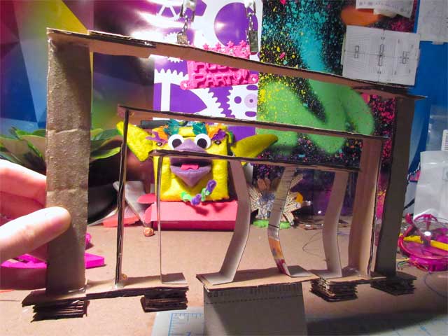
I was interested in finding out if adding multiple in the same axis of movement would have a chain effect to the movement of the main stage. How much less would it move for each mech stacked on top? How can these be combined to create a certain pattern of movement? Also was wondering what changes would have to be made to the design to fabricate it out of cardboard on a laser cutter.
Creating a press fit construction kit is a good way to experiment to start answering the questions.
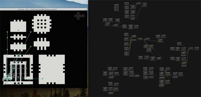
Modeling in Antimony
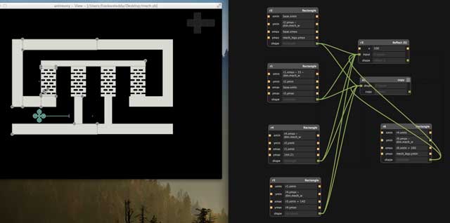
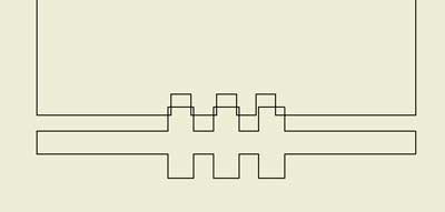
The first thing I started to model was the connection method. It is the snap-lock from the MTM. The middle part keeps the pieces aligned, and the outer clips can snap the pieces together.
My approach to the design was to reflect everything in the middle of the main rectangle. At the end of the main rectangle is an end piece. The two rectangles on the clip could be adjusted to be wider and closer together. Changing the material dimension would effect the height of the middle piece, and the distance to the bottom of the rectangle/triangle part of the clip.
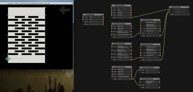
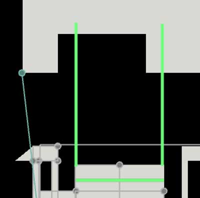
Next up I wanted to create a model for a parametric flexure design. The plan I decided to go with was to divide the width by 11 and create lines that are 3 times that amount. One row would have two lines, the other three. It was neat to be able to visually see the design change as various parameters were adjusted.
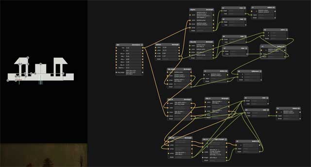
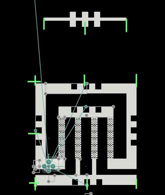
Now time to start the basic mechanism piece! Here you can see the flexure model being used. The width of the structure around it can change. The flexures can become taller, making the overall mech taller too. Likewise for the space between flexures. The distance to the output stage can also change.
Added to the design to create matching attachment pieces. I changed from the snap lock to three squares because of the size. There were a lot of pieces that were dependent on the input parameters.
The design ended up being too complicated and leading to a big fail. Details in the next section below.
Mistakes Made
Made a lot of errors while modeling. Learned a tough way about how to *not* do things.
I wanted to make a way to use the snap lock connector as flush instead of at 90 degrees. The design was not working out for me. I kept confusing the parameters and mixing everything up. Here was a mishap of trying to align the middle tab. Which should have been easy since the coordinates would be based off of the rectangle/2.
Next was the area for the clip. I tried changing numerous parameters but couldn’t make it align properly. Guess I just messed it up.
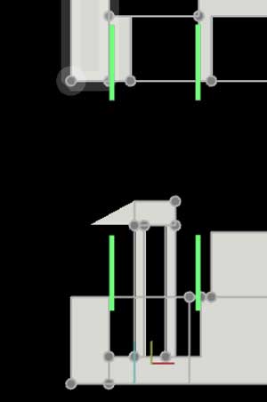
Similar problems with aligning the slots on the mech piece. How I eventually ended up fixing this was with a ‘construction’ rectangle, whos values I could use to align the tabs better.
Now for the worst mistake ever. When creating the mech and linking pieces, I never really closed out of the file and opened it again. When it happened that I had to open the file, I couldn’t. It’s too big, and my computer runs out of memory.
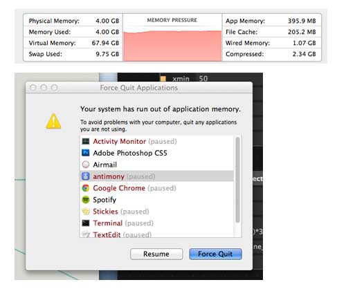
Just to clarify, this is not Antimony's fault. There were a lot better ways that I could have designed the mech and linking pieces. For instance, I made each little shape its own node. I should have been creating scripts with multiple shapes in it, and doing some of the iterations and unions in there.
Another way it could have been designed better was if the linking pieces were in another file. Although it would have been more annoying to input the values from the different files, at least I still would have been able to open them.
The design of the mech isn’t entirely parametric. If you adjust it, some of the shapes do not adjust as they should. Another mistake was making a wobbly tower of parameters that was too confusing to figure out each time. It was just too over-complicated.
Modeling in Autodesk Inventor
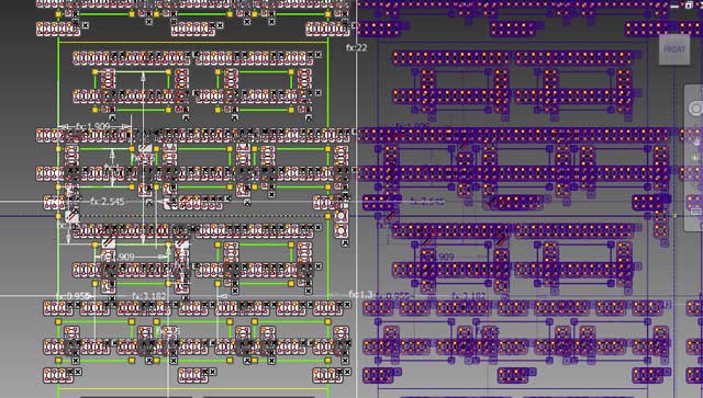
I decided to re-create similar pieces in Autodesk Inventor. I created a common part file that contained the dimensions for the material and kerf values. This was then linked in to each of the individual parts. A quick way of updating the parameters is with an assembly file.
For testing, I designed 5 mech pieces with minor differences:
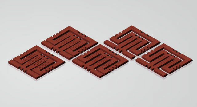
Here are all of the pieces:
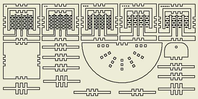
The models of the pieces were each extruded, then their base projected onto the drawing. Projecting just the 2D sketch would also show the constructions lines. Export as dxf, make sure the model scaling is ‘base view scale - model space’, as this is 1:1.
Open the dxf in Inkscape. Make sure automatic scaling to A4 is unchecked. The scale factor should be 1. From there, it can be edited for preparation to be laser cut.
Mistakes Made
I messed up the pattern on the flexures, but the bigger mistake was not realising this until much of the design was built up. At that point, there were a lot of constraints added. So when going in to fix it, this is what happened:
Another fail occurred when I was duplicating the design files. I opened the base part before copying the common part (the part with the parameters), which lead to the base losing its reference to the linked dimensions. It confused me for a while as to what was happening after not seeing the base updating properly.
Laser Cutting
The main laser cutter that is local to my city is currently unopperational. One of the mirrors is cracked, and the replacement is stuck in customs. Unfortunately other laser cutters nearby are exclusively for “real” students -- as if to say working on interesting projects and robots is not real.
So I reached out to a few friends with laser cutters. They agreed to run some test cuts! Cool!
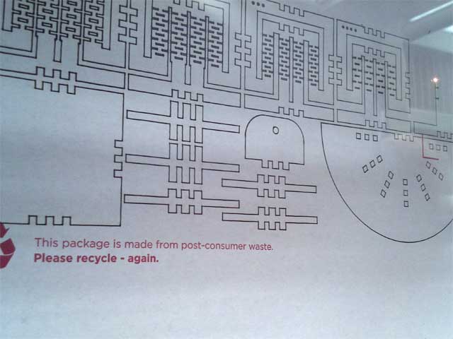
Recycling some cardboard with laser cutting the design:
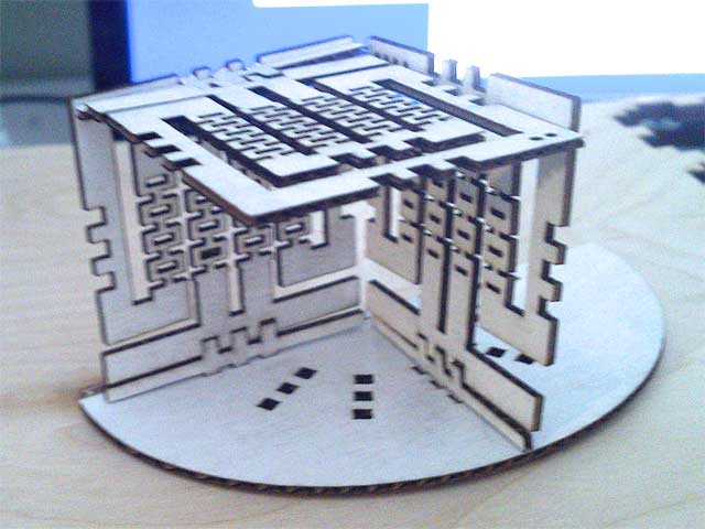
The cardboard was quite thin, and had a tricky time of attaching together. But a construction was still managed to be created:
Another go at it, with 3mm mdf this time:
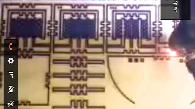
Feedback from both people was that the mechanism can move side to side just fine! Though, the flexures were weak in the z direction and some ended up breaking off.
For the first pass at laser cutting the mdf, the kerf value was a little off which caused the link pieces to be just a tiny amount too big for attaching to the mech.
Many thanks to Jaidyn Edwards and Kevin Osborn for their help with laser cutting the pieces!
When I go to EchoFab, I will be laser cutting the pieces and observing the movements even more closely to see which of the five mech designs works the best.
Flex Boards + Vinyl Cutter Notes
I’m excited to try making some flex circuits at EchoFab with a vinyl cutter there (hopefully). Here are some notes about things to keep in mind when doing this:
- Settings to adjust: force, speed, cut depth
- The settings will change day to day
- Check the holder of the knife, and check the blade
- There is a sequence to the cutting,
- Need to do test cuts
- Backing of the copper tape is designed to pull away - do not do the weeding on this
- Use masking tape to lift everything off,
- Apply to some sort of new backing
- Press it! Activate the adhesive on the copper tape!
- Pull the unwanted pieces away, in plane,
- Shearing makes it harder for the other traces to peel up
Summary
Trying to design the pieces as fully parametric in Antimony was challenging. In the future, I think I would go for semi-parametric designs, like the ones made in Autodesk Inventor, just to create quick prorotypes of ideas. After seeing which one is best, then design it in Antimony to make it fully parametric.
Struggled a lot with the dimensions of various lengths and relating them to other shapes. Especially when combining with more shapes, it became confusing.
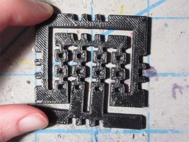
Of course, with all this said, it is nice to be able to adjust a few parameters and be able to make a few pieces on a 3d printer. For example, the flexure of this was updated a bit and the kerf changed to -0.4 (the size of the nozzle * -1).
Excited to laser cut the design and try it out. Also have a better idea for a flexure, for next time.
Design Files
You can find all of the source files in my repository