INPUT DEVICES
JILL HARTLEY YOKOTA, AS220 FAB LAB, PROVIDENCE, RI
ASSIGNMENT: Design a microcontroller board with a sensor and measure something. Make sensor align with final project, if possible.
This is the original documentation for the Input Devices assignment. I ran out of time to resolve the issues with this control board, but did complete a successful input device for my final project. Here is the documentation for the LED tact switch PCB I designed as a module to a Satshakit-derived ATmega 328 board.
INITIAL IDEAS...
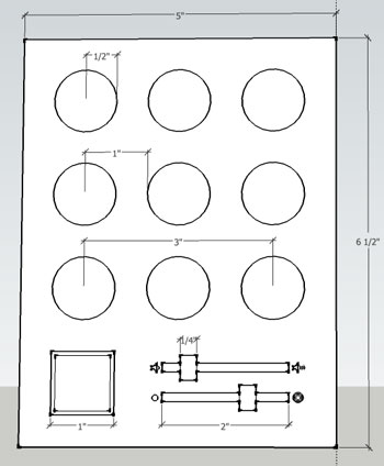
I wanted to get started on the control board for my final project this week. The control board is an interface to the illuminated roof that will be mounted on one of the interior GlowHouse walls. It will have nine programs triggered by nine illuminated tactile/momentary buttons arranged in an array. Additionally, there will be two potentiometers controlling brightness and volume together with an on/off switch to the interface. The control board will be a shield to a Raspberry Pi, which will act as a FadeCandy server and host for the animated sequences displayed on the NeoPixel array embedded in the HDPE roof of the GlideHouse.
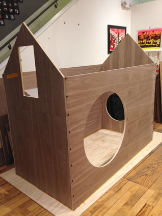
Here is a picture of the current state of the GlowHouse and a rough sketch of my design for the control board:
This is a preliminary electronics design layout for my final project:
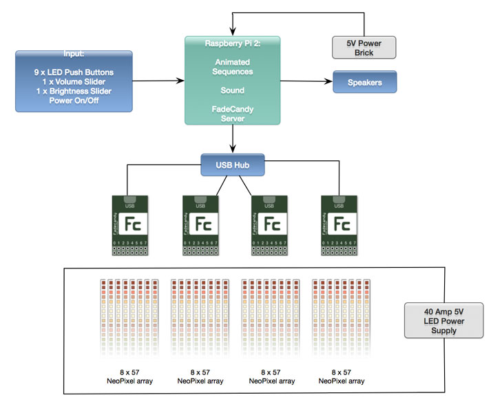
NOTE: the power requirements are crazy dangerous HIGH at 40 amps, which is only powering the 1600 NeoPixels used in my project at ~1/3rd capacity. Shawn and I have discussed and he has suggested limiting to 50-60 Neopixels. I am awaiting communication from a fellow AS220 peep who designed an LED cube with over 4000 neopixels to ask how he's managing power.
INSPIRATION
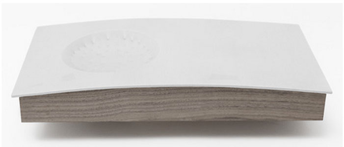
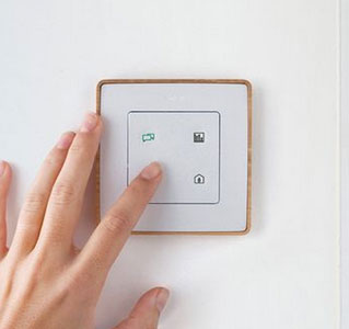
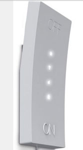
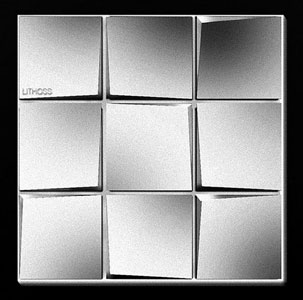
I have not yet modelled the 3d portion of the design, but have several ideas I'm still working through. I'd like the exterior of the control board to be a soft, white elastomer and I plan to mold and cast it. It will likely be "framed" in matching walnut veneer from the GlowHouse. Initially I planned to do slightly rounded buttons, cut-outs for the potentiometers and square for the on/off switch. Lately I am considering eliminating the "on/off" switch and having power triggered by pressing any of the programmed buttons. The interior of the elastomer buttons will have vinyl cut icons that will be visible when the control panel is "on." I've also thought about having a completely flat surface, except for a "prick" that the user touches, which triggers the illumination of the panel. Perhaps the potentiometers will change from being mechanical to capacitive to keep the surface flat, except for the prick. Still much to think about...
Here are some control panels that are inspiring my ideas:
COMPONENTS
I wanted very specific components for the control panel and found them on Mouser Electronics website. I chose blue LED illuminated low profile tactile switches for the array of program buttons and the same button in orange for the power button:
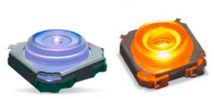
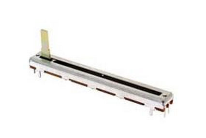
I also bought some slide potentiometers, since we did not carry them in the inventory:
MAKE YOUR OWN D*MN BOARD (AND PARTS)
Once exprensive shipping was underway, I got started designing the schematic for the control board. I soon discovered my fancy illuminated tactile switches were not in any of the libraries for Eagle and Fritzing and neither was the slide potentiometer. I had no choice but to design the components myself. Fritzing has a beautiful interface and I decided to give it a try for this project. I found some good tutorials about designing components for Fritzing's library and 36 hours later gave up on Fritzing after much "yak shaving." To shave a yak means to attempt a simple and straightforward task, but to get diverted by challenge after challenge after challenge. Yes, there's plenty of Yak Shaving at FabAcademy!

Fritzing had issues with importing .svg files and managing copper layers in the Parts Editor. I tried both Inkscape and Illustrator and every kind of .svg file possible. I also tried editing the .xml code. Phew. Too much work and aggravation. Got a good night's sleep and set out to create the part in Eagle the next morning!
I found a good tutorial on Instructables about making an Eagle component. Here is a snapshot of the end result:
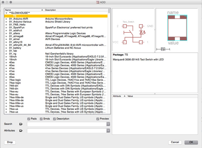
I talked to Shawn about my goals with the inputs project and he suggested I use the ATMega 328, since I would likely need more pins. He also advised that I use the resistor ladder layout to economize on pins. I searched the web for ATMega 328 board designs and came across Shawn's tutorial on Make: Build Your Own D*mn Board. I used Shawn's tutorial as a design aid, but started to feel the assignment getting too big and had to scale back. I still wanted to make the assignment applicable to the final control board, but opted to simplify and come up with a practice board first (especially since my components were expensive and I didn't have many spares). I used push buttons from the inventory and instead of making a Raspberry Pi shield, made a button input board with the ATMega 328 that will communicate with a NeoPixel breakout board for the Outputs assignment.
There was more yak shaving... After designing the board, Kenzo noted all my parts were through-hole and the size of the microprocessor was wrong. UG. Also, many of the components in Shawn's Make tutorial were not a part of our standard inventory. I made lots of substitutions to the design with Shawn's help and re-drew the board with the correct version of the ATMega 328. I am still not sure which package I was using erroneosly!
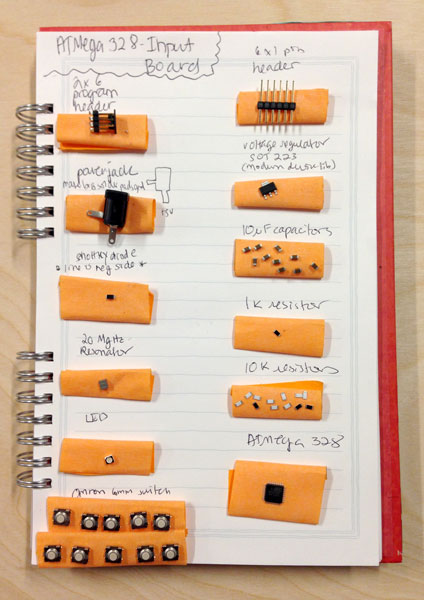
These are the finalized parts:
Here is the current version of the Eagle schematic and board views:
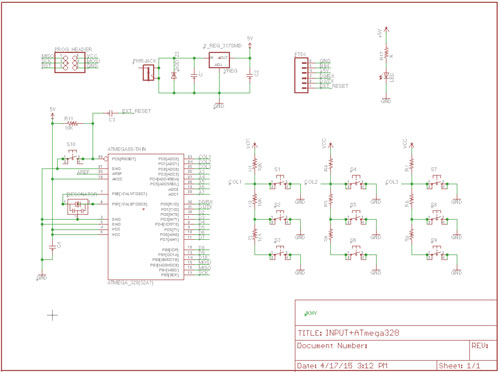
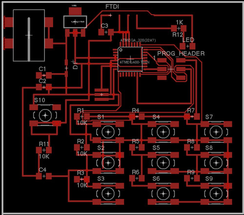
I spent several hours routing by hand and let Eagle do the routing of the last 6-7 traces. Lots of overlays and thin traces were created as a result. I will consult with Shawn next week about a better design and would like to keep it to a one-sided board, since it will be a shield in it's final project version.
ISSUES
Power jack wrong orientation on board
FTDI backwards on board
Multiple power labels (VCC, +5V, 5V) meant connections were not all joined
After manually altering traces to correct the power problem, a trace under the microcontroller had to be removed.
ATMega328 used (not 328p) which meant Arduino IDE needed a different bootloader file(?)
FILES
Here are the Eagle files for the nine-button input board in its latest version. NOTE: it needs to be re-routed in Eagle before being milled.