INPUT DEVICES, take #2!
JILL HARTLEY YOKOTA, AS220 FAB LAB, PROVIDENCE, RI
ASSIGNMENT: Design a microcontroller board with a sensor and measure something. Make sensor align with final project, if possible.
This is the second input device I made, since I ran out of time to resolve the issues with the first one. For my final project, I designed and made a sensor out of an LED tact switch that interfaces with a Satshakit-derived ATmega 328 board.
KEEPING IT SIMPLE
As the deadline approached for completing my final project, I had to simplify my goals in order to succeed at have a working prototype by June 24th. Instead of a battery-operated, IR-enabled, nine button, cloud-shaped enclosure with a custom membrane for an input board, I decided to do a wired, modular one-button input board mounted on an electronics slab(!) In the spirit of spiral development, I would like to build upon what I've done and achieve the bigger goals over time.
MODULAR DESIGN
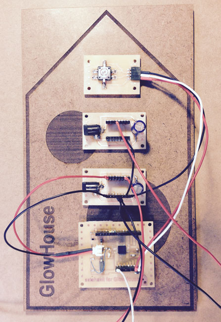
The long term goal for the GlowHouse input device is that it be a standalone board, so it made sense to start out building it that way. Since this design only has one LED tact switch requiring two pins, Shawn pointed out that a dedicated onboard microcontroller was unnecessary. So, this one uses two pins on the main board of my project, which is a derivative of the Satshakit Arduino design. As I add more LED tact switches and other features in the next spiral, I will also ad a microcontroller to minimize physical connections (jumpers) to other boards, enable handheld wireless usage and address scalability.
Electronics on a slab! Modular design of input (LED tact switch), output (96 x WS2812 array), microcontroller board and accessory power/ground/capacitance management boards.
BUILDING THE INPUT BOARD
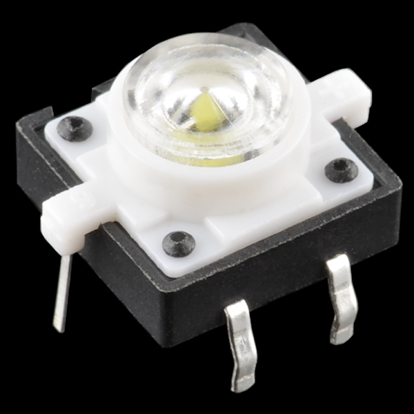
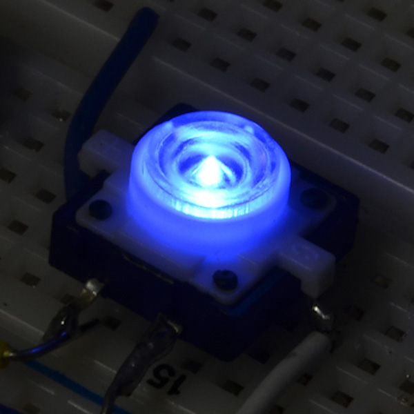
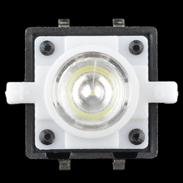
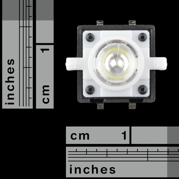
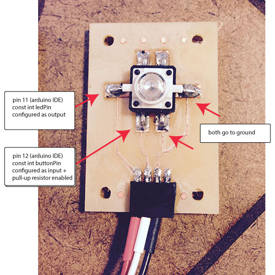
I've collected quite a few cool looking LED tact switches at this point, but decided to go with a blue one with a larger 12mm footprint from SparkFun since it had already been made into an Eagle library component. This one is a through hole design, but I intended to unbend the legs and use it as a surface mounted LED tact switch. It is also a momentary (vs. maintained) switch and remains active only as long as the button is being pressed.
The data sheet was not helpful and lacked basic pin-out information, so I asked Shawn to help me figure that out. This is what we came up with:
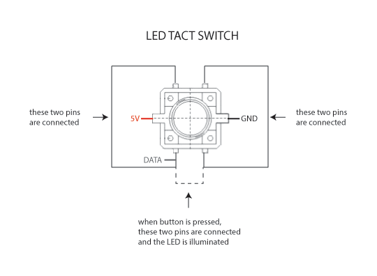
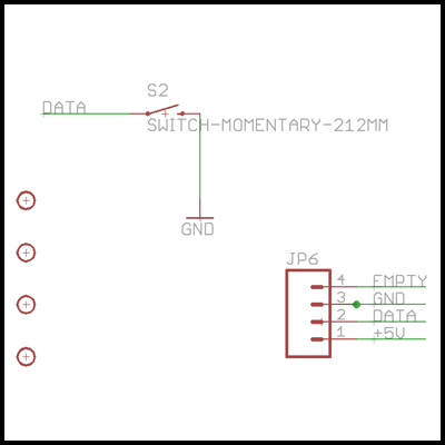
The simple Eagle files are shown below and can be downloaded here:
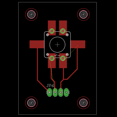
The board was milled on the Modella with offsets of -1 on the default FabModule settings for the 1/64th endmill and all default settings on the 1/32nd endmill used for cutting out the board and creating the stand-off holes. The traces were thinner than I had designed because we had some problems with our endmills, but they were all intact and thin was ok since the LED tact switch wouldn't be handling a lot of current. The pull-up resistor for the LED was enabled in the configuration of the pin in the Arduino IDE, rather than putting one on the PCB, which was another suggestion from Shawn.
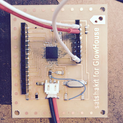
This is the Satshakit-derived ATmega 328 I made that provides the microcontroller support to the LED tact switch board. I modified the Satshakit design by removing a reset button to accommodate a sturdier 2 pin JST flexural connector for power and ground:
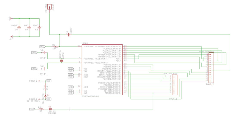
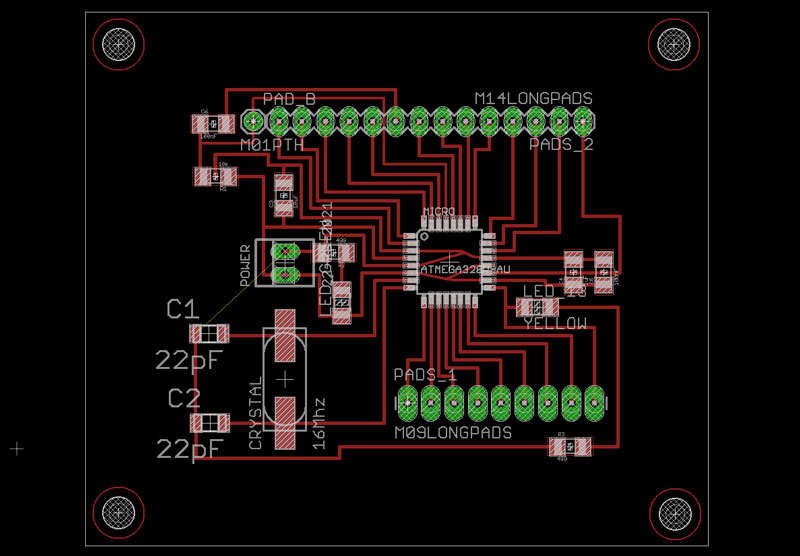
Here are the Eagle files for the revised Satshakit ATmega 328 board:
MODIFIED BUTTON SKETCH
The LED tact switch requires two microcontroller pins - one for the internal blue LED and one for the switch. The button sketch was modified to test the LED tact switch's ability to turn the Satshakit onboard red LED on and off. The tact LED was physically connected to pin 11, which was set up as an output. The button was physically connected to pin 12, which was setup as an input with the internal pull-up resistor enabled. The red LED on the Satshakit was connected to pin 13 and setup as an output. Everytime the button state is LOW, the tact LED and onboard LED are also LOW. When the button state is HIGH, both LEDs are HIGH as well. Every time the LEDs are high, they are receiving ~5v of power from the microcontroller. This code worked fine and other variations were experimented with, as well.
modified button from jill hartley on Vimeo.
Here is the code corresponding to the video:
    /*
      Modified Button with LED Tact Switch

    When tact button is LOW, blue tact LED is LOW and red Arduino LED is LOW.
    When tact button is HIGH, blue tact LED is HIGH and red Arduino LED is HIGH.

     The circuit:
     * LED on Arduino attached from pin 13 to ground
     * Tact button attached to pin 12
     * Tact LED attached to pin 11
     * Internal pull-up resistor enabled on pin 12

        ARDUINO LED: Physical pin 17 > Arduino IDE pin 13
        TACT SWITCH LED: Physical pin 15 > Arduino IDE pin 11
        TACT SWITCH BUTTON: Physical pin 16 > Arduini IDE pin 12

     created 2005
     by DojoDave
     modified 21 June 2015
     by Jill Hartley Yokota

     This example code is in the public domain.

     http://www.arduino.cc/en/Tutorial/Button
     */

    // constants won't change. They're used here to
    // set pin numbers:
    const int buttonPin = 12;     // the number of the pushbutton pin
    const int ledPin =  13;      // the number of the LED pin
    const int tactledPin = 11;    // the number of the tact LED pin

    // variables will change:
    int buttonState = 0;         // variable for reading the pushbutton status

    void setup() {
      // initialize the LED pin as an output:
      pinMode(ledPin, OUTPUT);
      // initialize the pushbutton pin as an input:
      pinMode(buttonPin, INPUT);
      // initialize the tact LED pin as an output:
      pinMode(tactledPin, OUTPUT);


       //configure pin12 as an input and enable the internal pull-up resistor
      pinMode(12, INPUT_PULLUP);

    }

    void loop() {
      // read the state of the pushbutton value:
      buttonState = digitalRead(buttonPin);

      // check if the pushbutton is pressed.
      // if it is, the buttonState is LOW:
      if (buttonState == LOW) {
        // turn LED off:
        digitalWrite(ledPin, LOW);
        // turn tactLED off:
        digitalWrite(tactledPin, LOW);
      }
      else {
        // turn LED on:
        digitalWrite(ledPin, HIGH);
        // turn tact LED on:
        digitalWrite(tactledPin, HIGH);
      }
    }