COMPUTER CONTROLLED MACHINING
JILL HARTLEY YOKOTA, AS220 FAB LAB, PROVIDENCE, RI
ASSIGNMENT: Make something BIG and original using the CNC router. Provide design files, tooling/feeds/speeds and materials used.
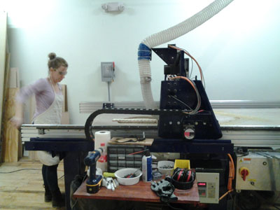
OH, WHAT A NIGHT (LOTS OF THEM)!!
Given we are nearly half way through the FabAcademy program, I've been contemplating my final project and how to make every assignment count between now and the end of the program. My biweekly commute to Providence from New York gives me ample time to brainstorm, scribble notes and listen to lectures and tutorials. "Build something big" is one of the the assignments I've most anticipated and I knew it would take time to design and make something worthy of the wondrous CNC machine. This was a marathon week, full of learning, challenges and lots of excitement about making something BIG!
Originally, my intentions were to make the wood framing of the treehouse this week, but after facing the hard cold facts that the platform my husband and kids built may not support a WikiHouse structure, I wasn't sure what to do. I broached the topic at home about "repurposing" the platform for a shed deck and putting up a stronger steel platform instead for the treehouse, but was met with wailing opposition and hurt feelings that took days to mend. Oops. I knew had to come up with something equally fun, otherwise the kids would disown me, since they really had their heart set on a treehouse. It was also time to get more organized and plan out the remaining assignments as they related to this new final project. With the new design, I've anticipated related project ideas for I/O, network, molding & casting, composites, application design, in addition to computer-controlled machining. Details to follow!
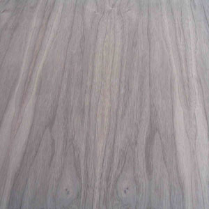
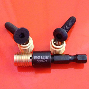
My new final project is called "Glow House." It is a prototype for a flat packed indoor children's bed that is meant to be a place for sleeping, cocooning and relaxing. The walls are constructed from walnut veneered formaldehyde-free plywood and the pitched roof is made from a pair of natural color High Density Polyethylene (HDPE) panels, which will have LEDs and other electrical components embedded within. There will be a touch pad attached to the interior of the back wall that will allow a child to select a night sky (constellations, shooting stars, moon) and lullaby (crickets, owls, frogs croaking). The semi-transparency of the natural HDPE will allow the LED "stars" to glow on both the interior and exterior of the roof paneling. I researched various plywood joinery options and ultimately decided to use "knock-down" hardware, which will allow the piece to be easily assembled/disassembled and packed flat, while also reducing complexity. I wanted the design to be simple, modern and easy to put together. I did a lot of reasearch over the last two weeks and got to know folks at Atlantic Plywood, King Plastic and E-Z Lok pretty well this week! Here are samples of the materials I've chosen for Glow House:

INSPIRATION, DESIGN & MODELING
After a couple of days playing with Rhino and Grasshopper, I decided to go back to SketchUp to model this project. It's very easy to get absorbed in the process of learning new software and not have much to show for it at the end of the day. The slow progress can be both frustrating and stressful on a tight schedule. I had to get the design underway quickly and felt reasonably comfortable with SketchUp, although I knew I'd be forfeiting parametricity and probably have to deal with some bugs and annoyances worked out already in more advanced 3d packages. Here is a basic model of Glow House:
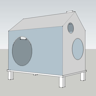
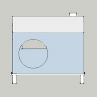
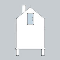
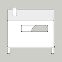
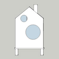
I took inspiration from a couple of sources, including the Umbra Casa tissue box and DucDuc, my favorite children's furniture design company. I also like the custom furniture of Casa Kids in Brooklyn, even though it looks a little "CNC'ish".
Umbra Casa Tissue Box by Mauricio Affonso:

Bed and table designs from DucDuc:
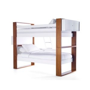
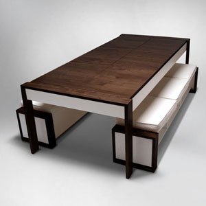
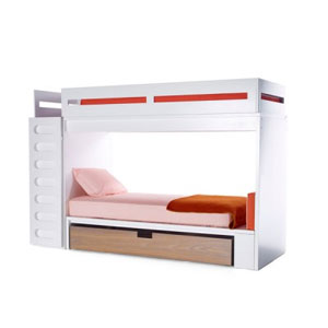
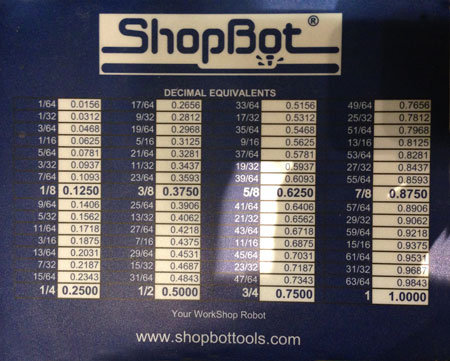
The modeling was somewhat straightforward, although I got myself into trouble creating walls and keeping them grouped and faced properly. I still don't understand the difference between creating a group vs. component in SketchUp, although according to one tutorial I should have been using the latter. I learned many keyboard shortcuts, which saved time and improved workflow. The design is tricky because there isn't much space for the threaded fasteners to embed in the cross-sectioned surface of the 3/4" plywood and they must be positioned very closely to the edge of the cutting path on the plane they attach to. Another lesson learned while putting together a design with lots of dimensions was to get a fraction-to-decimal conversion chart like the one below when designing to scale! Larry had one in the form of a mousepad by the CNC and it was a very useful reference during production.
PREPARING FILES FOR OUTPUT
After I modeled the design, it was time to create output that could be read by VCarve. A YouTube SketchUp to CNC Fabrication was very helpful in understanding the process. Here's the gist of converting a 3d model designed for CNC machining to a set of 2d images:
Layout 4'x8' rectangles representing the plywood sheets along the c plane in Sketchup.
Remove parts from the model that will not be printed (like casters).
Pull apart each piece of the model and lay flat on the plywood sheets. Clean up any stray geometry in the process.
Position or "nest" pieces on the plywood rectangles to make the most efficient use of the material, while anticipating how the plywood will be fastened securely to the CNC cutting bed. For more complex nesting, use VCarve's nesting feature.
Remove the faces of each oject and any non-planar geometry.
Delete 4'x8' rectangles and export one group of geometries at a time as either .dwg or .dxf file formats.
Import into VCarve for further processing.
This is what the flattened, laid out (nested) and defaced 3d model looks like:
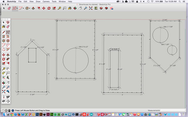
SketchUp has a really useful dimension tool that will indicate the measurement of a given line segment, or curve. I used it to double check my work and sure enough found a descrepancy in the length of the not-quite-matching roof panels. This required going back several steps in my workflow to correct, but at least I was able to practice the process.
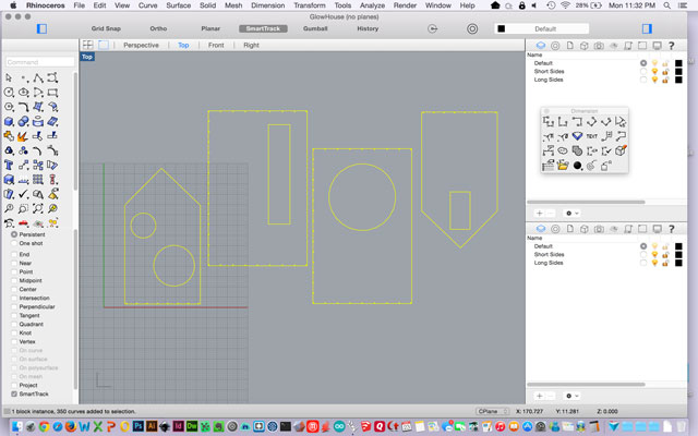
I purchased the commercial version of SketchUp 2015 because it had the 3d export features I needed. Lo and behold every time I tried to use them, the application quit unexpectedly. I spent a couple of hours debugging and trying to get SketchUp to export properly, but without success. Then I remembered what a great 3d conversion utility Rhino can be and was able to import the SketchUp file and export finally to .dwg and .dxf. Yay, for Rhino! Subsequently, Bas also pointed out that one can save a file to the SketchUp 2014 format and import it in VCarve (as of version 7.5), which was probably the simplest solution of all, but I had already used the Rhino method. Bas said that VCarve will also export to .svg, which was an earlier RFI I had submitted to the fabacademy mailing list.
Here's what it looked like in Rhino, before breaking down into four individual geometry collections:
Next, onto Vectric's VCarve! This program is used to create toolpaths for cutting parts on CNC routers, including the ShopBot. Here is the workflow and some of the tasks accomplished in VCarve:
Import .dxf or .dwg into VCarve.
In the "drawing" tab, indicate the size of plywood sheets, position parts, join vectors, indicate depth of cut.
Add tabs, or holes for fixturing the substrate to the CNC router sacrificial layer.
Add filets or dogbones, if needed.
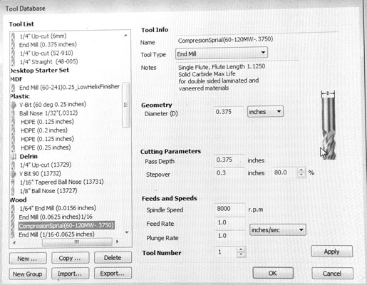
Next make toolpaths and specify tooling. Larry let me use his fancy spiral carbide endmill, knowing that I needed a very clean finish on both sides of the veneered plywood and no splintering. It worked GREAT, but produced a lot of chips and dust from the MDF sacrificial layer and plywood.
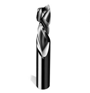
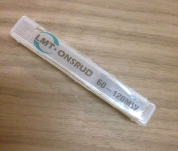
We created a database entry for this tool in VCarve, since it wasn't a stock library part:
.
Create progressive toolpaths, selecting either Drill, Pocket, or Profile cuts for each. "Drill" goes only up/down. "Pocket" creates an opening by moving the endmill in the x and y directions and progressivley down in the z direction. "Profile" cuts all the way through along a path. I used all three kinds of cuts in my design.
Save and output file to G code, which breaks paths down into line by line descriptions of how the machine should cut the material.
TEST CUTS ON CNC ROUTER
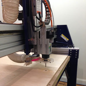
The CNC was zeroed in the x and y direction using the keyboard (by pressing "k") to move the spindle into position. The "d" key allowed finer movement of the spindle, which was especially helpful when raising (pageup) or lowering (pagedown) the endmill. We aligned the endmill by eye down the center in both the x and y directions and choose cuts > zero the XY axes in the ShopBot software for zeroing the x and y location. The aluminum plate for the calibration in the z direction was put on the bed, grounded and calibrated using in the software by selecting cuts > zero the z-axis with plate. We repeated this zeroing out procedure for each piece of wood cut. I found ShopBot Reference Manual reference document about our ShopBot to be helpful.
Finally, we were ready to start cutting! There were several things to test before using the good stock.
Calibration of Endmill settings
The manufacturer's recommended hole diameter for the 1/4"-20 threaded inserts was 3/8" and this is the size that was drawn in the 3d model on all planes. We did a test cut and found that the hole size was too small for the threaded insert. Then, we did several more tests and found the optimal hole size to be .455" for the threaded inserts. There very well may be a chart out there showing drill diameter vs. cut diameter, but I didn't think of that while modeling the design.
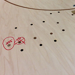
Calibation of cut depth
Next, we had to calibrate the cut depth in order to eliminate splintering and have the cleanest possible results on both sides of wood, particularly the side facing the sacrifical layer. This proved to be somewhat challenging, as the bed wasn't level all the way around. We experimented with the spindle location for zeroing out the z direction. If cut depth was too shallow, there would be a "skin" of veneer on the board's underside which would have to be cut or filed gently out (in one direction), often with the result of splintering. If cut depth was too deep, a lot of material would be ruined in the sacrificial layer(s). With every test, we vacuumed out the hole and used a flashlight to determine if the cut had pierced through to the sacrificial layer and by how much. Ultimately, we choose a cut depth of .87-.88 and had fairly good results with some minor repair work.
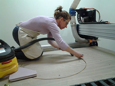
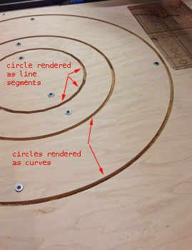
Rendering of shapes, especially circles
We also had to see if the circles would render as a series of jagged connected lines, or as a smooth curve. Historically, there have been problems with Rhino and SketchUp curves being interpretted as the former, whereas VCarve circles and curves alway render properly. I needed to know if I should redraw the circles in the Glow House in VCarve. As the test shows above, the VCarve curves rendered beautifully and the Rhino/SketchUp generated curves did not. I redrew the circles in the imported .dxf files in VCarve and forged ahead.
Corner angles
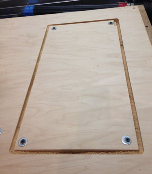
Lastly, I wanted to check the corner angles of the rectangular shapes. The results were great, since I didn't want hard right angles and the endmill created a "soft" corner.
GITRDONE!!
Larry from our lab is awesome. He is patient, knowledgable and extremely kind and was at the lab all afternoon and until 3:00 am assisting with my project. At 1:00 am, when I asked him whether we should wrap up and reconvene the following day, his response was "Why? Let's gitrdone!" I rallied and we successfully cut all four boards. Thank you, Larry!!
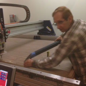
One of the challenges cutting my project was that I (poorly) designed it to have 4' walls. Fortunately, fancy hardwood veneered plywood actually has 48-1/2" x 96-1/2" dimensions, so Larry convinced me we should give it a try rather than completely redesigning Glow House to have a shorter dimension. In 2d, no big deal to make a rectilinear change in length. In 3d for a beginner, it takes hours (and advil) to make a dimensional change to a model. The side walls were the nail biting 4' boards and I'm happy to say that they were cut successfully, even the ones with fastener holes. This is a prototype, so should there be a version #2, I will shorten those walls slightly to avoid this issue.
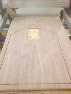
Here is a shot of this beautiful wood before being cut. I love walnut. It has a warm chocolate hue and modern feel, beautiful grain and reminds me of our Pennsylvania family farm that had lots of hardwood trees and where I spent many weekends as a kid.
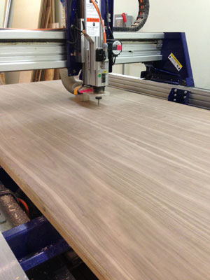
The first panel was a side panel with two circles and fasteners along the base. No issues rendering after re-drawing in VCarve thankfully! The circles were screwed into the sacrificial layer to prevent movement. We used washers + screws to hold them down since the hole size was bigger than the screw diameter.
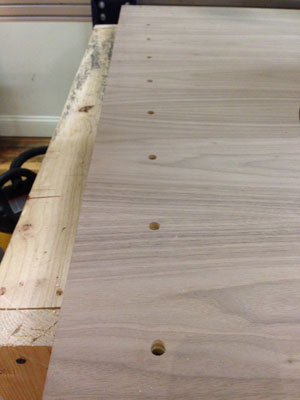
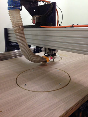
Next, the cut circles were removed and the walnut board was clamped with a piece of scrap put on top of the cut-out and drilled into the sacrificial layer. Lastly, the first board has been cut and with great results! There was no splintering and the cuts were beautiful and smooth. Yay!
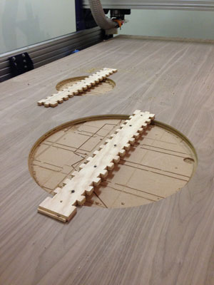
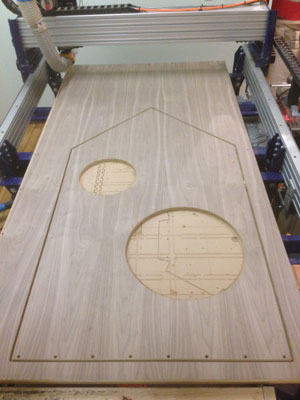
The second panel was one of the nail biters with a 4' dimension in the design. We should have put the edge of the board with the fastener holes along the other side of the CNC bed, because the edge was unsupported (the sacrificial layer started at about 1/2" in). We didn't realize this until the job was already underway. I taped the edge in an effort to reducing splintering with some success. There were more splinters on this panel for some reason, so we increased cut depth slightly for the following panel.
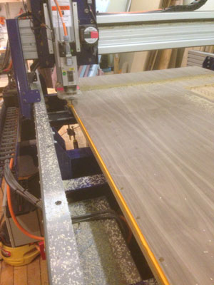
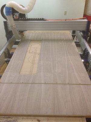
The third panel was another one with a 4' dimension, but this time we oriented the hole side towards the side of the router that had sacrificial layer support underneath. As you can see in the first picture, dust collection was a bit of a problem, since the skirt was missing on the spindle. We had to do a lot of manual digging out of dust and vacuuming. In hindsight (and after experiencing a 12 hour headache), we probably should have worn respirators given the amount of MDF dust generated from cutting into the sacrifical layer.
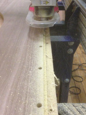
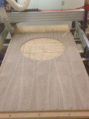
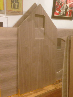
The fourth panel cut beautifully and we felt like pros at this point. Thankfully, due to all of our preproduction testing, there were no disastrous issues with wasted, expensive material! These four panels are all now in the AS220 gallery space, since the shop space is tiny. There's still much to be done...
RACEWAYS (ADDED 05.20.15)
As my project has advanced, I've been able to figure out more of the customizations needed to the GlowHouse. One such customization is the addition of interior corner raceways to hide cable runs from the roof to the underside of the floor. In order to blend, I chose to make the raceways out of the walnut ply, though I only had two scraps with enough length. These turned out to be quite the engineering challenge, but Larry "the magician" expertly guided us through the process and the cut pieces in the end were hard earned perfect.
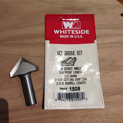
I purchased a Vee Groove bit for the ShopBot in order to do 45 degree chamfer cuts on the roof panels and raceways. This bit was substantial in size, heft and price(!), but I needed it in order to cut these pieces of the GlowHouse. The test cut was beautiful with the lighter plywood core and dark walnut surface and the cuts very cleanly.
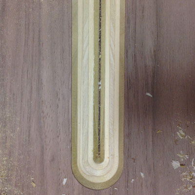
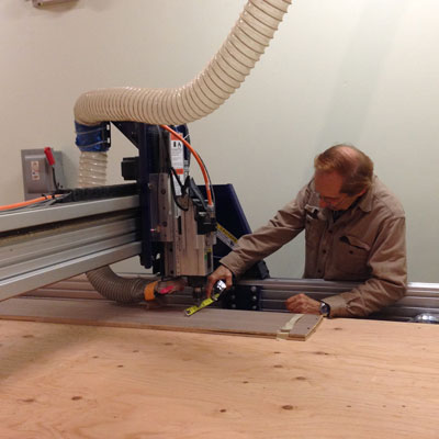
It took quite a bit of trial and error to understand whether we should cut inside, outside or on the line of the toolpath. Ultimately we determined it was necessary to cut ON the toolpath. We had no margin for error since there were only two pieces of wood to do these cuts and not much waste. Here we are air routing to see where the bit will cut.
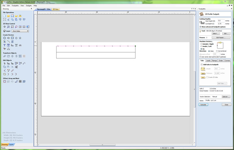
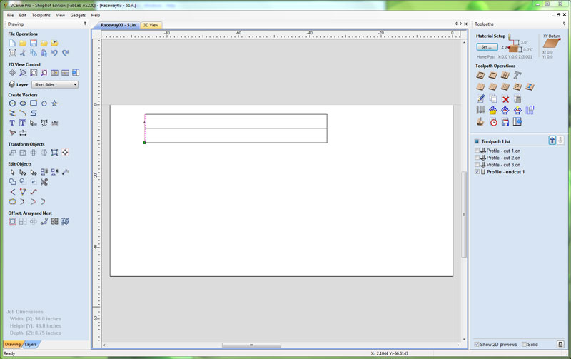
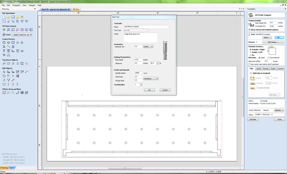
These are the settings used for the chamferred edges of the raceway cutouts. In order to conserve wood, one cut was made down the center to create two pieces with 45 degree cut edges. We did two sets of two raceways.
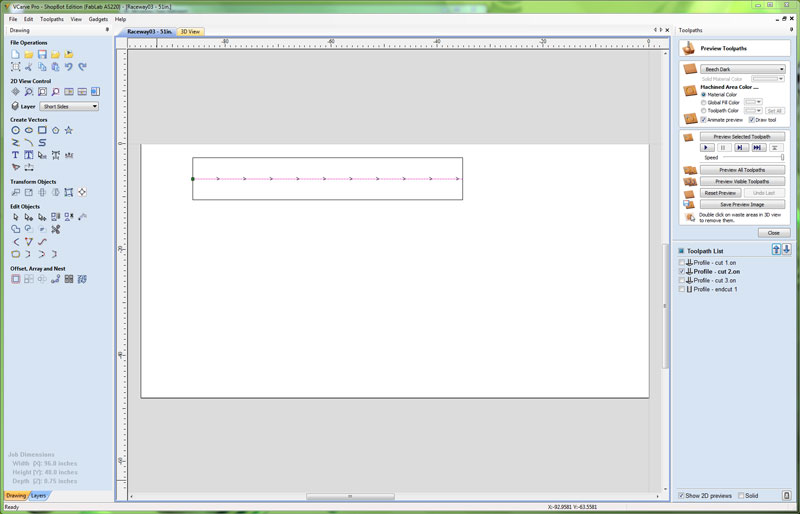
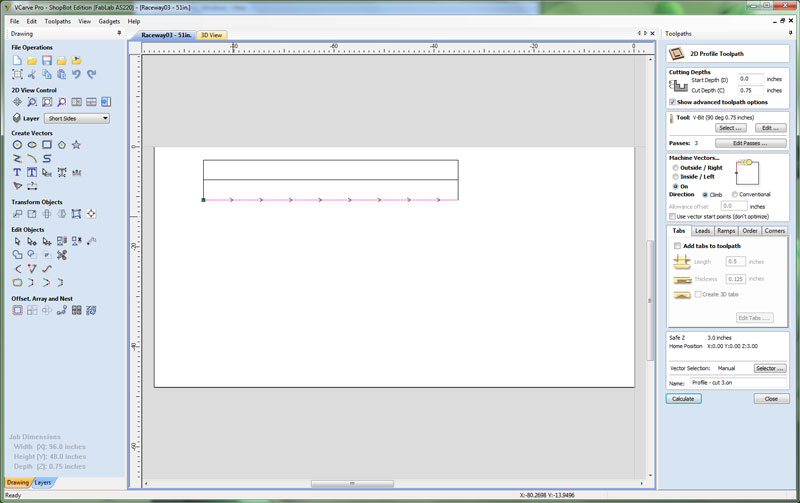
This screenshot shows the toolpath used for the end cuts, which were done with a 3/8" spiral compression bit, but was taken with the toolpath settings not visible unfortunately. The main difference was that the cut depth was 0.8mm and the cut was made OUTSIDE the machine vectors.
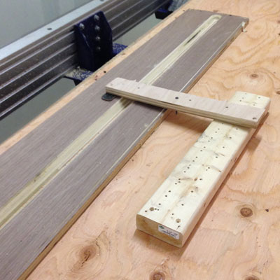
We did lots of clamping and bracing to secure the wood to the bed without having to drill into it to fixture securely. We did lose one of the tips of the (brand new) spiral compression bit when the spindle nicked one of the clamps because the stop button lagged when pressed. That made both Larry and me tremendously saaaad :(
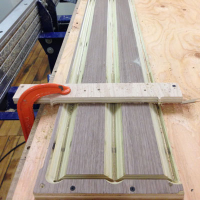
The results were terrific! We had very clean knife edged 45 degree chamfered cut raceways from very modest sized pieces of wood. They were lightly sanded to remove splinters and are ready to be fitted. I now call Larry "the magician" and bow down to him.
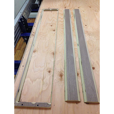
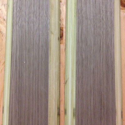
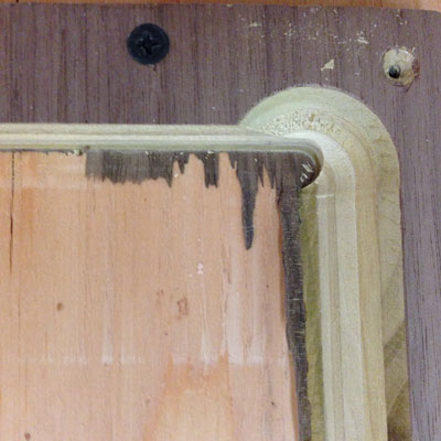
The only "oops" was that because the sacrificial board isn't completely flat, one of the endcuts wasn't clean because the bit didn't go deeply enough to cut the veneer on the opposite face. Luckily, this was easily repaired and may be trimmed off in the fitting of the raceways anyway.
ROOF PANELS (ADDED 05.23.15)
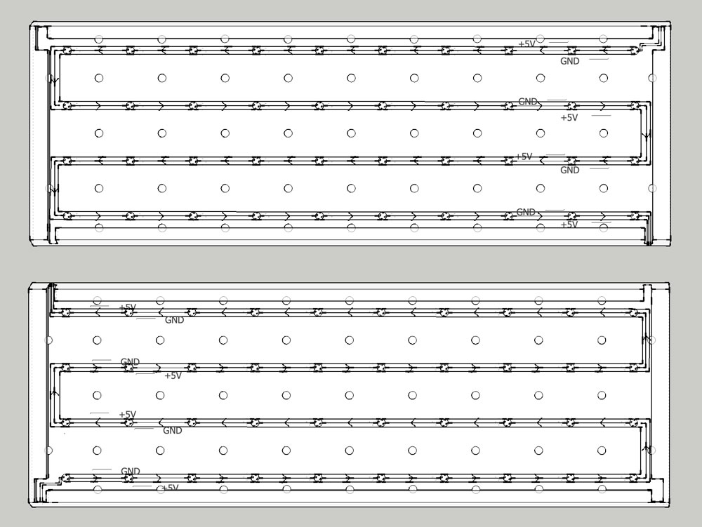
The roof panels will be fabricated out of HDPE. There will be two matched panels and the WS2812 (Flora NeoPixels by Adafruit) array will be embedded between the plastic layers. I will use 3/4" HDPE as the base layer and it will be milled down to 1/4" interior with a 3/4" full height frame and 1/2" perimeter shelf and peg spacers throughout the interior. There are cable routes cut out of all four corners to allow for routing of cables down through the interior of the GlowHouse corners and to the underside of the base, where they will be house in an enclosure. There will be a separate insert for each panel made of 1/4" HDPE and cut to fit that will function as the "lid" to the base layer. Given the complexity of the design, I decided to make a prototype in plywood. Here is the initial SketchUp design showing these details, in addition to the snaking of electronics through the spacer pegs:
3D FILE CLEANUP
As usual, there was a bit of cleaning up to do in VCarve. The source 3d file used layers which seemed to duplicate geometries and complicate groupings in VCarve. We had many extraneous geometries to remove and the semicircular pegs around the perimeter of the interior could not be edited easily. We removed the semicircular pegs and added partial length shelves instead. We also added drill holes to the perimeter shelves in both the base and lid files.
CREATING TOOLPATHS
Next, we created seven individual settings and toolpaths for each cut on the first panel (they are both identical). Here is a list of the toolpaths and the order in which they were cut:
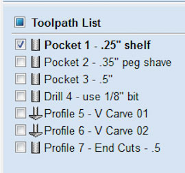
Pocket 1 - .25" shelf (recessed inset for "lid"):
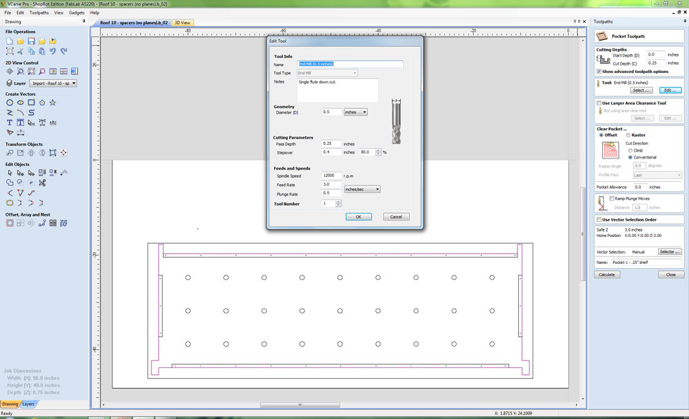
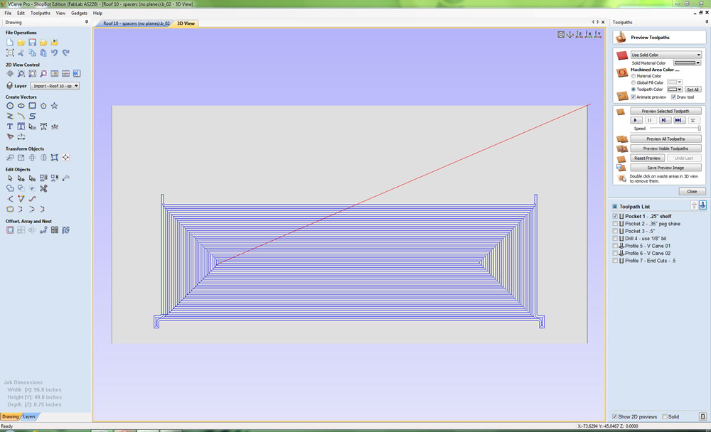
Pocket 2 - .35" peg shave (to accommodate thickness of velcro):
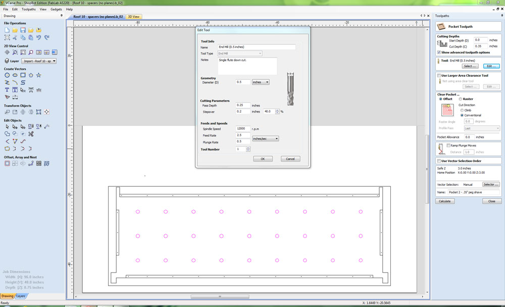
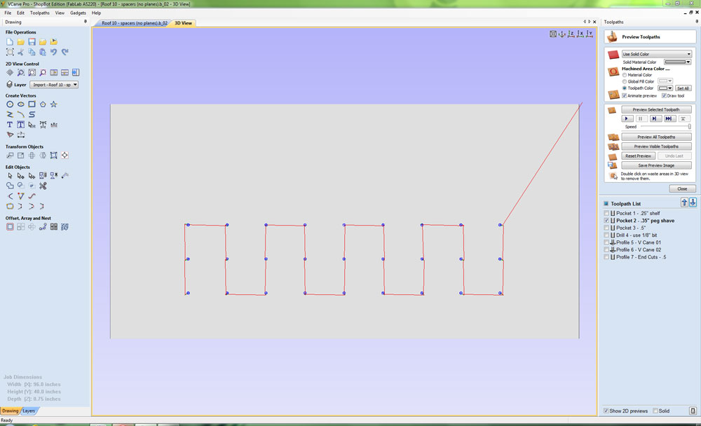
Pocket 3 - .5" (creates base layer, where electronics will embed):
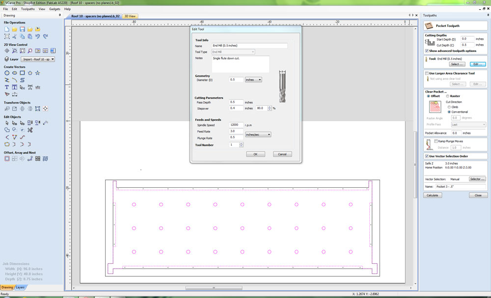
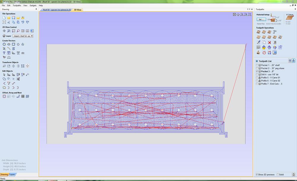
Drill 4 - use 1/8" bit (where "lid" will be screwed into base):
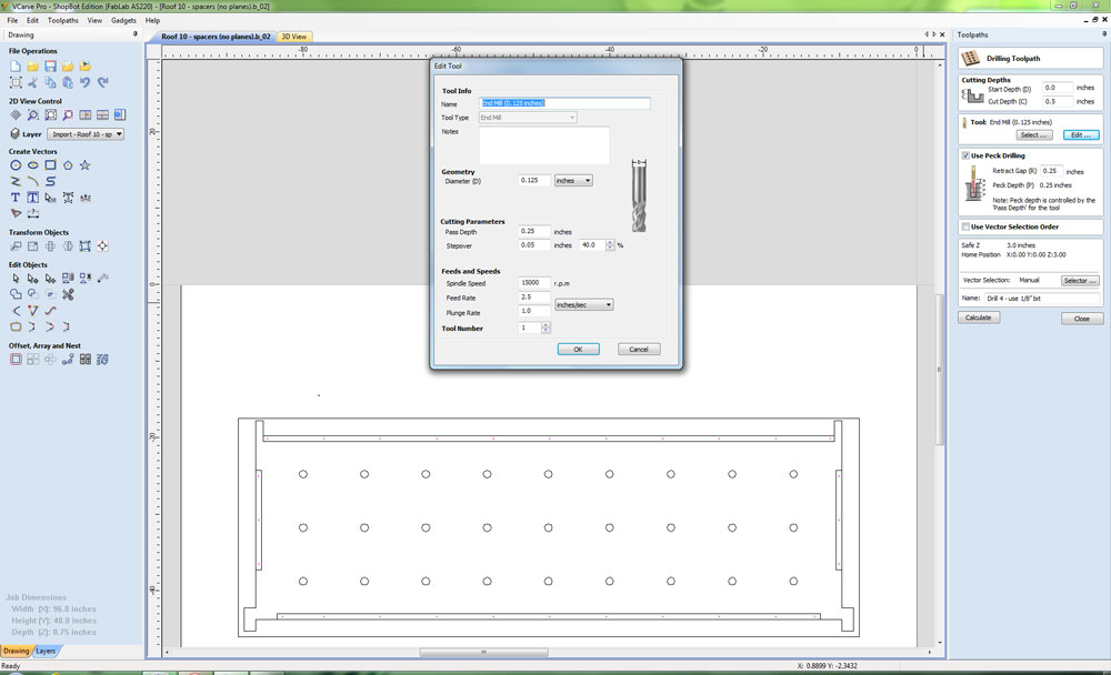
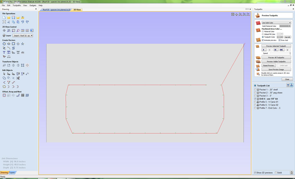
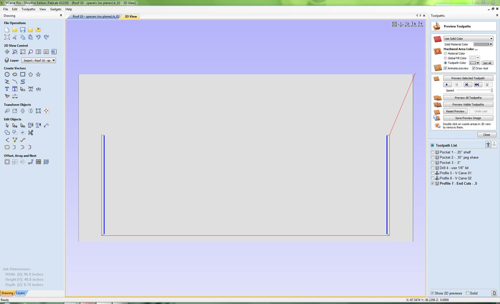
Profile 5 - V Carve 01 (chamfor roof ridge to 45 degrees):
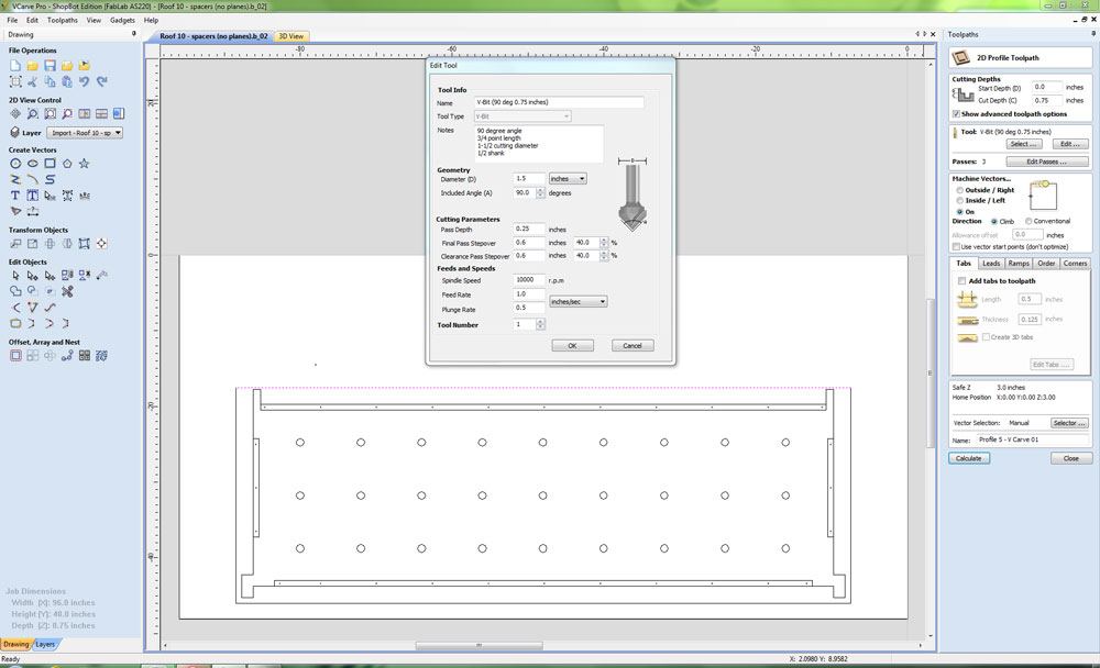
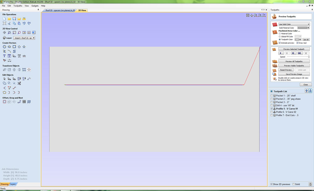
Profile 6 - V Carve 02 (chamfor roof edge that meets GlowHouse wall to 45 degrees):
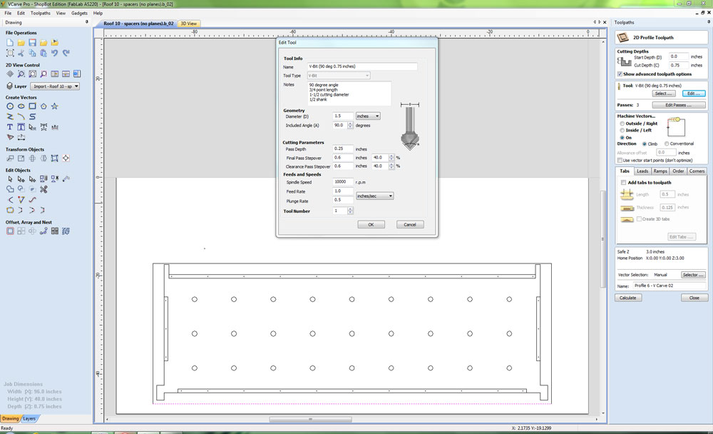
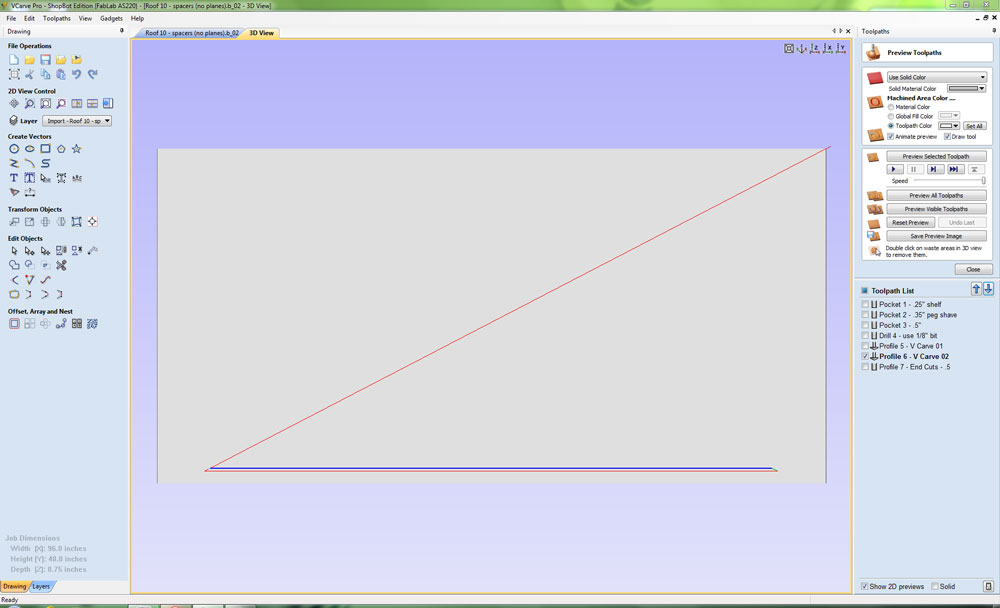
Profile 7 - End Cuts - .5 (trim end pieces, .5" bit):
CUTS
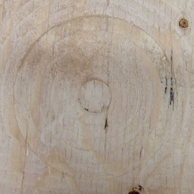
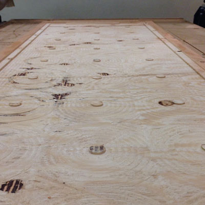
Peg spacers (these will space the lid from the electronics and be affixed to the lid with velcro). Here is an animation of this beautiful cut!
Shelves (these will space the lid from the electronics and be affixed to the lid with screws):
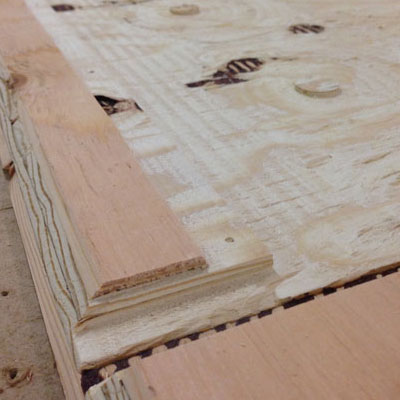
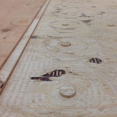
Cable routing (will feed into raceways when panels are assembled). The picture on the right shows the warping of the plywood where the bit did not cut all the way through despite a .8" deep cut setting for .75" stock:
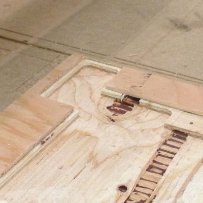
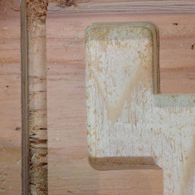
45 degree mitered cut made with V groove bit:
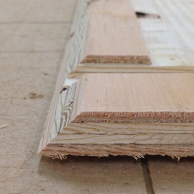
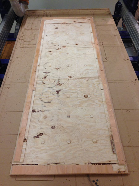
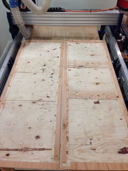
Roof prototype panels completed. Note to self: plywood is a terrible material for prototyping CNC cuts! Too many issues with knots, splintering and irregular lamination.
FABRICATING IN HDPE
It was a good thing we prototyped in plywood, because the exact dimensions were off by several inches and had to be corrected by referencing the actual model. Additionally, one of the roof panels had to be sized 1/8" wider along the short edge, since the re-cut walnut panel with the two holes was still off by 1/8". I'm beginning to suspect VCarve as the possible source of the smaller measurement problems, since one must zoom all the way in on an image in order to get the granularity of pixel-by-pixel nudging and perhaps I didn't do that in the earlier models.
Given the cost of this material, I observed a moment of silence and said a short prayer to the ShopBot gods while shooting this picture of a full sheet of 3/4" uncut King Plastic "natural" untextured HDPE.
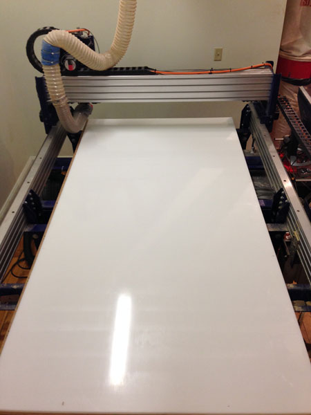
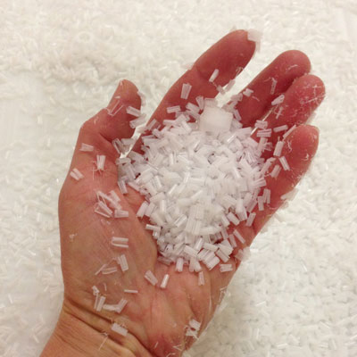
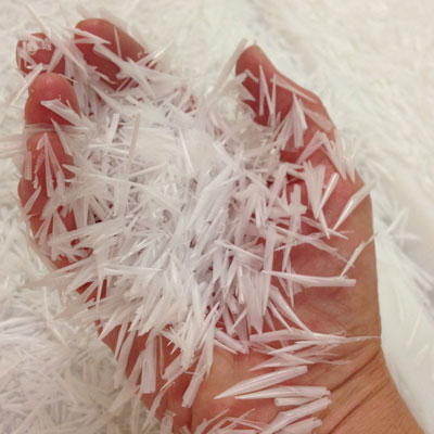
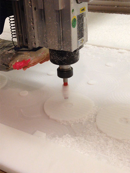
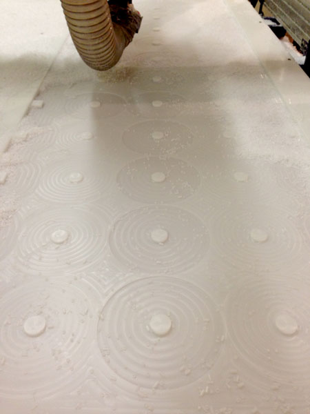
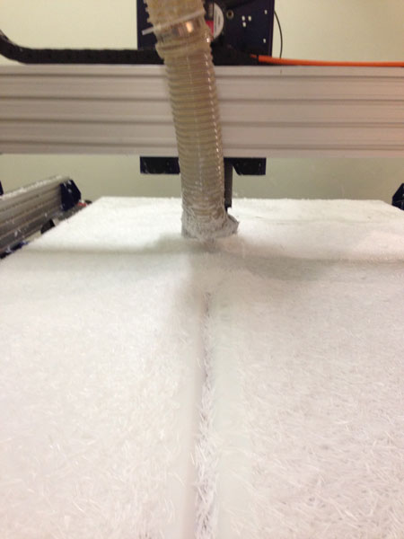
The HDPE machined beautifully, but made a big, BIG mess that required hours of vacuuming, since the skirt of our Shopbot for the dust collection system is out of commission. The small shavings were from the fluted bits and the larger shavings were from the v groove bit:
There are about 15 toolpaths for various cuts in the roof panel design! I was thankful to be working with Larry again, since two brains are always better than one (and his is waaaaay sharper than mine in the wee hours of the night!) I made screenshots of all the tweaks we made to the settings and toolpaths we did, since the bits were mostly upcut bits and the settings somewhat specific to the HDPE. The screenshots for Roof Panel #1 can all be downloaded here.
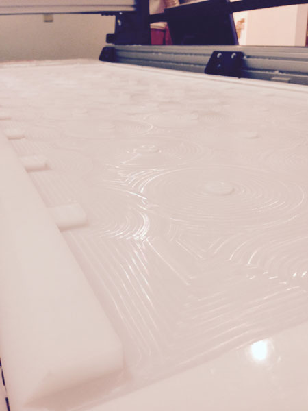
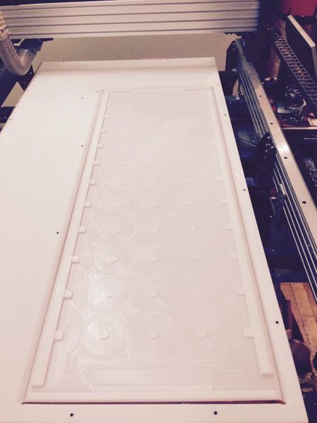
Here is a sampling of the cuts made:
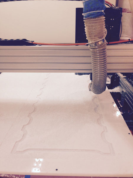
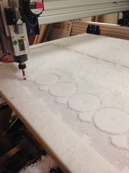
...and a cool video showing the elegance of the cuts and robotic controlled milling!
This is a sketch of a ledge that will be used to attach the roof panel to the side of the wall:\
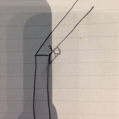
It has a v groove cut on one side and straight cut on the other:
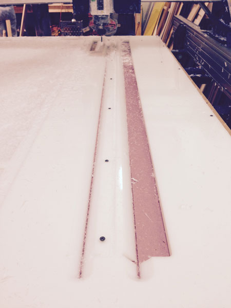
Here is a picture of the .25" lid that is placed inside the .75" cut out piece and a picture of the base and "Larry the Magician" with lid fitted together:
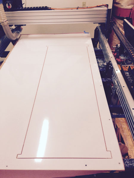
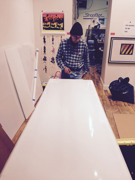
It took many (10+) hours to complete the first roof panel, ledges and lid. Unfortunately, we had a calibration error on the second sheet of HDPE of 1.5" that proved to be unrecoverable in terms of design modification and necessitated ordering another sheet of HDPE. We did a little manual work to dogbone the sharp corners of the first lid into place on the base. The second lid was made with dogbones added in VCarve. The picture on the left also shows one of the cable outlets:
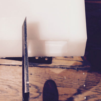
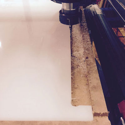
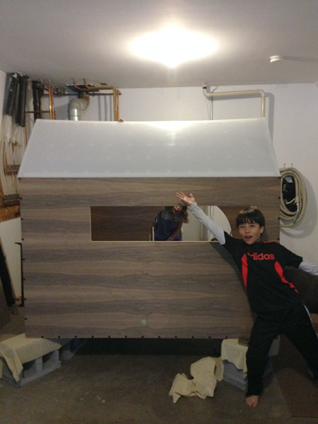
Roof panel #1 was put into place on the GlowHouse and fit perfectly this time! Kaden says, "YAY!!" The second roof panel was created more or less identically the following week and used the same toolpaths.
DESIGN FILES AND TOOLING/FEEDS/SPEEDS
Here is the SketchUp model for the GlowHouse wood structure.
Here is the model of the GlowHouse roof showing the initial LED matrix layout.
Here is the model for the raceways.
Here are the CNC files (toolpaths, settings, screenshots) for the GlowHouse wood structure.
Here are the CNC files (toolpaths, settings, screenshots) for the GlowHouse HDPE roof structure.
NEXT UP: THE ROOF BECOMES AN OUTPUT DEVICE!
After fabricating the roof panels and lids, they will be made into an output device by adding a matrix of 8 x 12 WS2812 LEDs and be controlled by custom hardware. This work can be found on my "Outputs" page.
POST DEADLINE "TO DO"...
Repair splintered veneer edges.
Sand and finish.
...catch up on sleep!!