OUTPUT DEVICES
JILL HARTLEY YOKOTA, AS220 FAB LAB, PROVIDENCE, RI
ASSIGNMENT: Add an output device to a microcontroller board you've designed and program it to do something.
THE ROOF PANELS BECOME AN OUTPUT DEVICE!
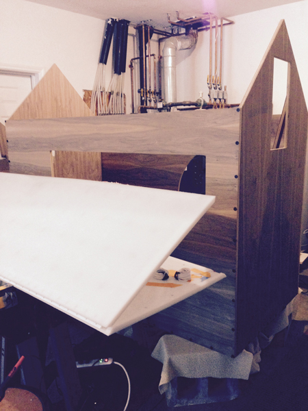
After weeks of design revisions and fabrication trials, the roof panels were finally made into output devices.
MATERIALS
The full list of materials to make the roof panels is in the BOM spreadsheet and includes 96 AdaFruit branded WS2812 Flora Neopixels, version 2. The Flora Neopixels are circular PCB-mounted WS2812s with appropriate resistors and large holes for the serial wiring of power, data and ground. They are typically used for wearable applications and were chosen because they provided enough surface area to be velcro-attached to the HDPE substrate and made wiring a large quantity of WS2812s feasible. I was instructed that these would be fine to use.
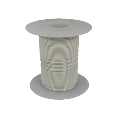
There were two types of stranded copper wire that were used. The wire used to connect the WS2812s to each other serially was 20 gauge (white) and the wired used for the power and ground rails was 18 gauge (white). An Adafruit tech support agent advised me on the gauge to used after discussing my project and Shawn and I verified using an online tool intended for gauge sizing. White was chosen for the entire project so that it would be less visible through the semi-transparent HDPE.
DESIGN
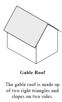
The roof style is a simple gable design, which has right angles at either end as shown:
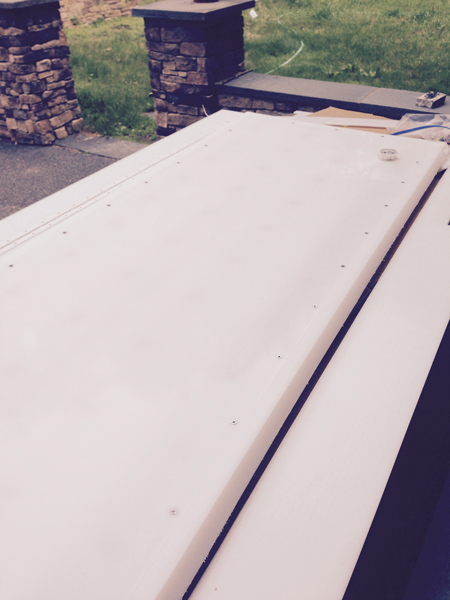
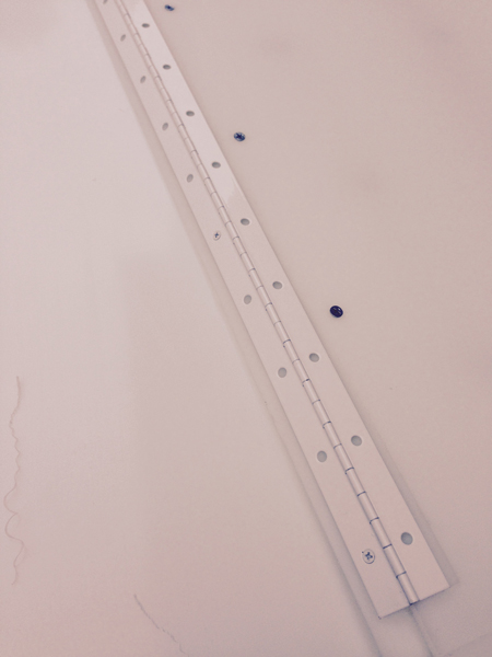
The roof panels were designed in SketchUp, VCarve and Illustrator. In the image shown below, the two panels are laid out in the orientation in which they were connected. A six-foot-long piano hinge was attached where the panels meet in order to form the ridgeline, which allows the panels to bend and form a right angle to make the shape of a gable roof.
There are three depths that were created with the 3/4" HDPE. The electronics are laid out on the 1/4" layer, the spacers are laid out on the 1/2" layer and the outer frame is full height in the 3/4" layer. The lids (not shown) are screwed into the base layer to make the entire panel flush and 3/4" thick. There are outlets for wire passage at all four corners of each panel.
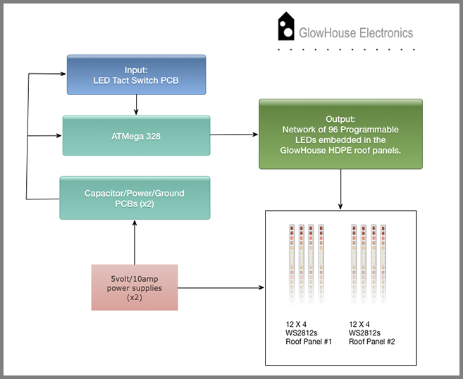
The roof contains a matrix of 8 x 12 WS2812 LEDs that are controlled with an ATMega 328 Satshakit-derived board with two custom made capacitor/power/ground shields for managing power to the LED tact switch input board, ATmega 328 board and WS2812 matrix. Each strand of 12 x WS2812s is wired into a power and ground rail at one end of the array. Each WS2812 has four holes for connecting and soldering wire: power, ground, data in and data out. The direction of data flow is marked on each PCB and allows the WS2812s to be arranged in a serpentine "daisy-chained" configuration.
The light gray wire shown in the diagram is data and the arrows indicate data flow. The red wires shown are for power and tap into a power rail along the left side of the wiring layout. The black wires shown are for ground and tap into a ground rail parallel to the power rail along the left side of the wiring layout. The yellow colored square, circles and rectangles are spacers that the lid once inset into the base layer will rest upon in order to prevent crushing of the electronics. Industrial strength, low profile velcro will be used to bond the spacers to the lids in order to minimize any sagging.
.png)
This is a summary flowchart showing the electronics design described above:
PRODUCTION
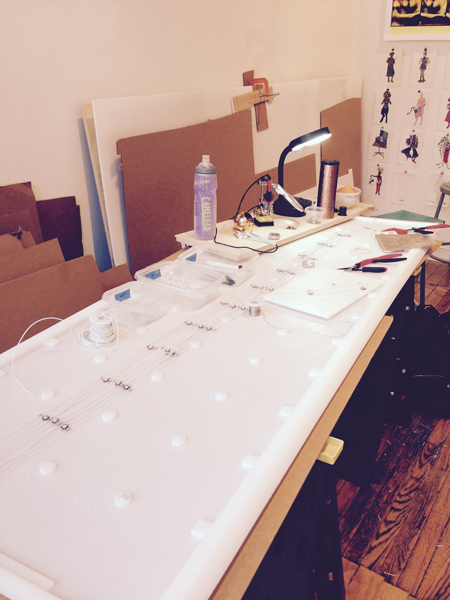
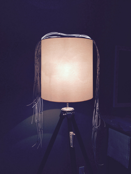
Creating the matrix was time consuming and tedious and took place in both Rhode Island at AS220 and home in upstate NY. The matrix of the first panel was made using individual pieces of wire segments that were soldered together connecting one WS2812 to the next at about 6" intervals and at four connection points (power, ground, data in, data out) each. All of these individual wire segments were cut and straightened by hand. Piecing the matrix together in this way resulted in strands that were not very flat or uniform in length, since even with careful measurement there were slight variations from one LED to the next in length of wire. Also, any that I had to redo were pretty lumpy and bumpy since it's hard to straighten out twisted wires with solder residue. Once made, I hung the strands over a lamp to keep them relatively straight and untangled.
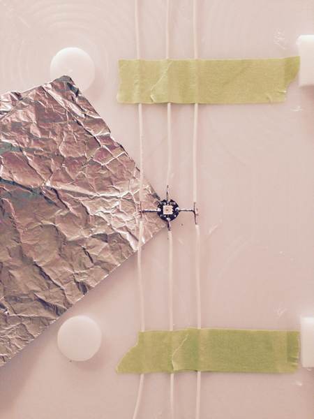
For the second panel, I only used short wire segments to connect the data lines running down the middle of the PCB mounted WS2812s. Single full length 7' strands with spliced in connection points for power and ground were used instead for power and ground, since these wires ran along the left and right sides of the Flora WS2812 PCBs. I used a multi-layer square of tin foil to slide under the WS2812 when soldering to prevent the plastic from melting. This method resulted in more uniform lengths, neater appearance and faster production time (2 days vs. 4 days per panel).
What I didn't realize was that the matrix in the first panel wouldn't match the matrix in the second panel. The length of the strands is 1-2" longer in panel #2. This was discovered at 4:00 am after 22 hours of soldering and I decided just to let it be for now. Correcting the strands in the first panel would require either unsoldering 48 WS2812s (messy, prone to damaging the components and time consuming), or ordering new WS2812s and wire and there was no time in my schedule to do this. I matched them up the best I could and hoped it wouldn't be too noticeable.
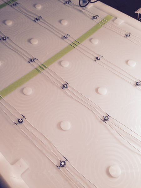
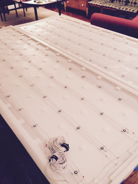
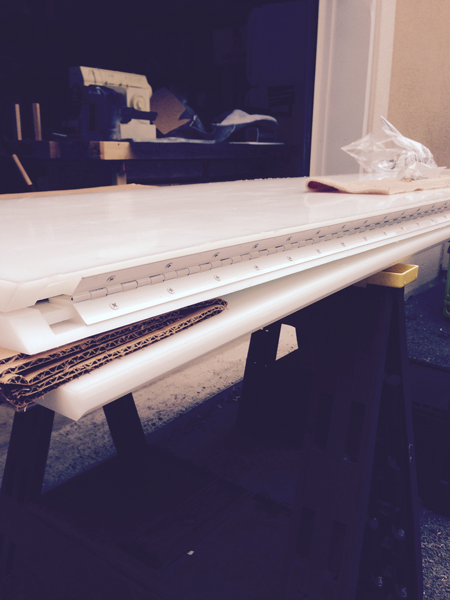
Here are the wired up panels!

BOARDS
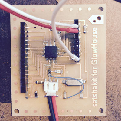
This version of the GlowHouse could have been driven by an ATtiny microcontroller-based board since the WS2812 matrix and the tact switch both only required three pins total. However, I wanted the option of adding IR, WiFi, SD card storage and sound in the future, so I opted for a modular system based on the ATmega 328 microcontroller instead. Using a modular system meant that any of the desired future features could be added with a breakout board and connection to an available pin on the ATmega 328 board. I made sturdy jumper cables using color coded solid copper 24 awg wire and attached heatshrink to the ends to provide a solid "bumper" when plugging into connectors. They are very tight fitting and not easily disengaged. The electronics will ultimately be stored in a locked steel enclosure, so the connections should be easy to protect (see below).
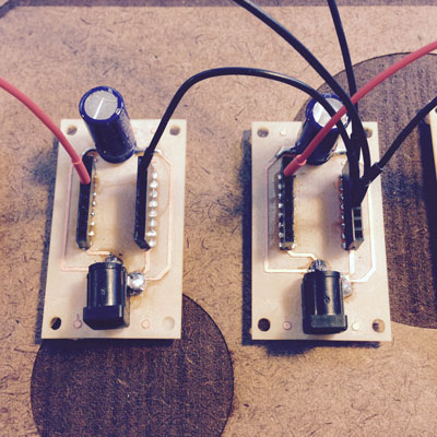
I was curious about Daniele's Satshakit which is based on the ATmega 328 and decided to give it a try. I added on to it by creating a separate LED tact switch input board and two capacitance/power/ground boards to manage power and cleanup wires for my project. I also modified the Satshakit design by physically removing the reset switch, so that there was room for a flat, flexural (JST) joint style 2-pin power and ground connector. Daniele used a 2 pin header in his design, but in the first Satshakit I made it proved to be too delicate structurally and detached from the traces.


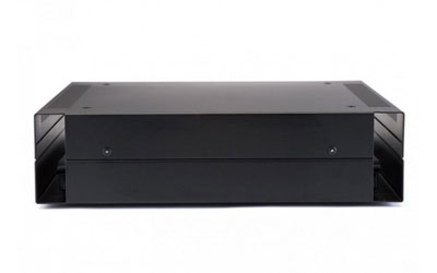
This is the protected enclosure with openings for cable and wire routing that will be mounted under the GlowHouse and store the modular board system:

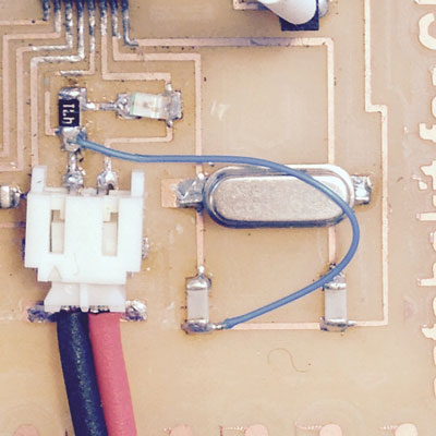
Initially, I had some difficulty burning the bootloader to my ATmega 328 board. After discovering that the LED for power had burned out, I replaced the LED and a resistor whose value was too low. Further troubleshooting with Nadya revealed that there was a short that had been created when I removed the reset button traces. I had accidentally severed a ground connection. This was resolved by using a tiny jumper wire to reconnect ground:
After these minor repairs, I used another Arduino as a bootloader following Daniele's instructions and succeeded in burning the bootloader. Here is his connection schema for programming Satshakit with an Arduino:

Once everything was connected, I selected "Arduino as ISP" and the "Arduino UNO" as the board in the Arduino IDE. Next, I selected Tools > Burn Bootloader. The status area of the IDE showed the bootloader to burn successfully.
CODE
Once the boards were made and the bootloader successfully installed, it was time to do some code tests. I downloaded and installed the AdaFruit Neopixel library from GitHub and started out with a short strand of only 3 x WS2812s to keep things simple.
I used this reference from Daniele's documentation to find the Arduino pinout on the Satshakit:
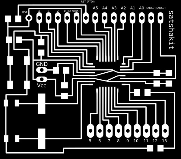
I also compared it to this pinout for clarification:

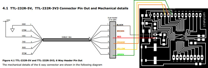
I connected the FTDI cable using jumper wires to program my board, as indicated in Daniele's FTDI connection schema and plugged the FTDI ground jumper into one of the power boards I made.
Simplified NeoPixel Test
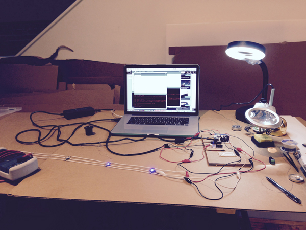
I played with a simplified and low power version of the Neopixel Strand Test example. This sketch could be powered by the ATmega 328 board since there were only 3 x WS2812s drawing a maximum of 180mA if all were on at full brightness. The short strand of 3 x WS2812s was plugged into physical pin 9, which mapped to Arduino IDE pin 5. Ground, power and data were sequentially connected to the corresponding WS2812 wires and the sketch was uploaded. It worked! The lights cycled through red, green and blue chase sequences and I modified the delay to see if the sequence was also erasing prior "pixels" and it was. Here is a video of this test:
simple test from jill hartley on Vimeo.
This is the "simple_test" code:
    // Simple NeoPixel test.  Lights just a few pixels at a time so a
    // 1m strip can safely be powered from Arduino 5V pin.  Arduino
    // may nonetheless hiccup when LEDs are first connected and not
    // accept code.  So upload code first, unplug USB, connect pixels
    // to GND FIRST, then +5V and digital pin 6, then re-plug USB.
    // A working strip will show a few pixels moving down the line,
    // cycling between red, green and blue.  If you get no response,
    // might be connected to wrong end of strip (the end wires, if
    // any, are no indication -- look instead for the data direction
    // arrows printed on the strip).

    #include

    #define PIN      5
    #define N_LEDS 3

    Adafruit_NeoPixel strip = Adafruit_NeoPixel(N_LEDS, PIN, NEO_GRB + NEO_KHZ800);

    void setup() {
      strip.begin();
    }

    void loop() {
      chase(strip.Color(255, 0, 0)); // Red
      chase(strip.Color(0, 255, 0)); // Green
      chase(strip.Color(0, 0, 255)); // Blue
    }

    static void chase(uint32_t c) {
      for(uint16_t i=0; i
Modified Button Sketch
The next test was to experiment with the LED tact switch. The LED tact switch requires two pins - one for the internal blue LED and one for the switch. The button sketch was modified so that when the tact switch button is pressed, both the red LED on the Arduino and the blue tact LED would be OFF. By default, the red LED on the Arduino and the blue tact switch LED are both ON in this code. This worked fine and other variations were tried successfully. Here is a video of this test:
modified button from jill hartley on Vimeo.
Here is code from one of the variations. In this test, when the blue tact LED is on and the button is pressed, it turns off and the red Arduino LED is on:
    /*
      Modified Button with LED Tact Switch

    When tact button is LOW, blue tact LED is HIGH and red Arduino LED is LOW.
    When tact button is HIGH, blue tact LED is LOW and red Arduino LED is HIGH.

     The circuit:
     * LED on Arduino attached from pin 13 to ground
     * Tact switch pushbutton attached to pin 12
     * Tact switch LED attached to pin 11
     * Internal pull-up resistor enabled on pin 12

        ARDUINO LED: Physical pin 17 > Arduino IDE pin 13
        TACT SWITCH LED: Physical pin 15 > Arduino IDE pin 11
        TACT SWITCH BUTTON: Physical pin 16 > Arduini IDE pin 12

     created 2005
     by DojoDave
     modified 21 June 2015
     by Jill Hartley Yokota

     This example code is in the public domain.

     http://www.arduino.cc/en/Tutorial/Button
     */

    // constants won't change. They're used here to
    // set pin numbers:
    const int buttonPin = 12;     // the number of the pushbutton pin
    const int ledPin =  13;      // the number of the LED pin
    const int tactledPin = 11;    // the number of the tact LED pin

    // variables will change:
    int buttonState = 0;         // variable for reading the pushbutton status

    void setup() {
      // initialize the LED pin as an output:
      pinMode(ledPin, OUTPUT);
      // initialize the pushbutton pin as an input:
      pinMode(buttonPin, INPUT);
      // initialize the tact LED pin as an output:
      pinMode(tactledPin, OUTPUT);


       //configure pin12 as an input and enable the internal pull-up resistor
      pinMode(12, INPUT_PULLUP);

    }

    void loop() {
      // read the state of the pushbutton value:
      buttonState = digitalRead(buttonPin);

      // check if the pushbutton is pressed.
      // if it is, the buttonState is LOW:
      if (buttonState == LOW) {
        // turn LED on:
        digitalWrite(ledPin, HIGH);
        // turn tactLED off:
        digitalWrite(tactledPin, LOW);
      }
      else {
        // turn LED off:
        digitalWrite(ledPin, LOW);
        // turn tact LED on:
        digitalWrite(tactledPin, HIGH);
      }
    }
Combine Sketches: LED Tact Switch Triggers 3 x WS2812 Sequence Sketch
The next logical step was to have the LED tact switch turn on the 3 x WS2812s chase sequence. Here is a video of this working:
03simple button from jill hartley on Vimeo.
The code follows:
    // Simple NeoPixel test.  Lights just a few pixels at a time so a
    // 1m strip can safely be powered from Arduino 5V pin.  Arduino
    // may nonetheless hiccup when LEDs are first connected and not
    // accept code.  So upload code first, unplug USB, connect pixels
    // to GND FIRST, then +5V and digital pin 6, then re-plug USB.
    // A working strip will show a few pixels moving down the line,
    // cycling between red, green and blue.  If you get no response,
    // might be connected to wrong end of strip (the end wires, if
    // any, are no indication -- look instead for the data direction
    // arrows printed on the strip).

    #include

    #define PIN      5
    #define N_LEDS 3

    Adafruit_NeoPixel strip = Adafruit_NeoPixel(N_LEDS, PIN, NEO_GRB + NEO_KHZ800);

    const int buttonPin = 12;     // the number of the pushbutton pin
    const int ledPin =  11;      // the number of the tact LED pin

    int buttonState = 0;         // variable for reading the pushbutton status

    void setup() {

          // initialize the pushbutton pin as an input:
          pinMode(buttonPin, INPUT);

          // initialize the tact LED pin as an output:
          pinMode(ledPin, OUTPUT);

          //configure pin12 as an input and enable the internal pull-up resistor
          pinMode(12, INPUT_PULLUP);

      strip.begin();
    }

    void loop() {
        // read the state of the pushbutton value:
          buttonState = digitalRead(buttonPin);

        // check if the pushbutton is pressed.
        // if it is, the buttonState is HIGH:
        if (buttonState == HIGH) {
            // turn LED on:
            digitalWrite(ledPin, HIGH);
         }

         else {
            // turn LED off:
            digitalWrite(ledPin, LOW);
          }


      chase(strip.Color(255, 0, 0)); // Red
      chase(strip.Color(0, 255, 0)); // Green
      chase(strip.Color(0, 0, 255)); // Blue
    }

    static void chase(uint32_t c) {
      for(uint16_t i=0; i
Combine Sketches & Add-On: LED Tact Switch Triggers 96 x WS2812 Sequence Sketch
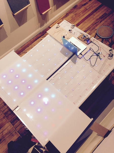
Finally, it was time to test a sketch on the roof panels. The previous sketch was modified to accommodate 96 x WS2812s. The goal for this initial development spiral was to modifiy a sketch, upload it to the Atmega board, press an LED tact switch and have the animated sequence play successfully in the roof array. We had to add a resistor to the data input line because the WS2812s lit, but somewhat randomly and did not resemble the chasing light sequence specified by the sketch. Afterwards, the results were much more predictable and everything worked! Here is a video of it working:
04simple button from jill hartley on Vimeo.
The only change to the code in the previous example is shown below:
#define N_LEDS 96
Nadya's Sketch

I worked with Nadya (a former FabAcademy student) to troubleshoot the various issues mentioned that came up with the electronics and programming of the roof. He took the code further and wrote a sketch with a zig-zag pattern that allowed the pixels to be addressed by number, which is something we discussed as being a "next step." He was eager to try this out and I was happy to see code that did much more than my simple chase sequence. I look forward to working further with his code in the next spiral of development, when I'd like to experiment with programming twinkling stars. Here is a video of Nadya's code:
05nadya strandtest from jill hartley on Vimeo.
Here is the code he wrote with comments I revised/inserted, which was built upon the code in the previous examples:
    #include

    #define PIN 5
    #define N_LEDS 96

    const int buttonPin = 12;     // constant number of the pushbutton pin
    const int ledPin =  11;      // constant number of the LED pin

    int buttonState = 0;         // variable for reading the pushbutton status

    Adafruit_NeoPixel strip = Adafruit_NeoPixel(N_LEDS, PIN, NEO_GRB + NEO_KHZ800);

    void setup() {

      strip.begin();

      strip.show(); // Initialize all pixels to 'off'

       //THE ILLUM LED TACT SWITCH HAS BOTH LED AND PIN TO CONFIGURE
       //initialize the tact LED pin as an output.
      pinMode(ledPin, OUTPUT);

       //configure tact button pin as an input and enable the internal pull-up resistor.
      pinMode(buttonPin, INPUT_PULLUP);

 			     }

    void loop() {

		//turn tact LED ON when button is LOW
        //button unpressed = HIGH
        //button pressed = LOW and connected to ground(?)
        //read the state of the button value

      buttonState = digitalRead(buttonPin);

        //is button unpressed (HIGH?)
        //if yes, then turn tact LED OFF

      if (buttonState == HIGH) {

        digitalWrite(ledPin, LOW);
           strip.clear();

  						       }

      else {
        //is button pressed (LOW?)
        // if yes, then turn tact LED ON

        digitalWrite(ledPin, HIGH);
        //erase all pixels
      		while(1){
        		for(int i=0; i<12; i++) {
        		for(int j = 12; j>=0; j--){
          		writePixel(i,j,strip.Color(50,i*30,i*50));
          		delay(10);
          		writePixel(j,i,strip.Color(50,i*30,i*50));
        			}
      		}
      }
      }
    }

    static void chase(uint32_t c) {
      for(uint16_t i=0; i
ASSEMBLY
After the WS2812 matrix was completed and tested, the assembly of the roof was fairly straight forward. The lids and spacers had pre-drilled holes made with the Shopbot. The lids helped to straighten out the warping base layers (thankfully!!) and the fit was very tight. The screw heads still need to be painted white to blend better with the white HDPE.
Attaching the piano hinge was a nail biter because the screws nearly poked through the mitered edge. They came with the piano hinge and were just slightly too long. There are bumps in the ridgeline where many of the screws nearly broke through. Thankfully, only one or two slightly did break through the material and are not too noticeable. I worked with a woodworking friend named Terry to attach this hardware, since I was worried I might make a mistake in the orientation.
We didn't fully anticipate the difficulty we would have putting the roof on. It was very heavy once the panels were hinged together and awkward to lift and open. Terry and I decided it was a job for more than just the two of us. I called on the guy who mows our lawn (Paco) and he brought a friend (Cesar) over to help with the roof raising. The three of us were able to lift and orient it properly. Paco and Cesar were humored by my project and couldn't imagine why anyone would build such a bohemeth(!)

FILES
Here are the 2d/3d roof design files.
Here are the Eagle files for the electronics designs.
Here are the sketches used to display in the roof.
