About me
Final project -
development
Final project
Weekly projects
Wk 5 3D Printing and
Scanning (Feb 25)
Note:
Assignment for Week 5:
• design and 3D print an object (small, few cm)
that could not be made subtracively;
• 3D scan an object (and optionally print it)
Presented and discussed final
project development with Tomas Diez during regional
review. This was followed in the afternoon with Neil
Greshenfeld's introduction to 3D Printing and
Scanning.
Assignment: Design of an object for 3D Printing
Slightly intimidated by the week ahead, I eased and
loosened my mind into the idea of 3D printing by doing a
pastel rendering of a vessel with an enclosed sphere. It
helped me consider how I might approach developing
certain forms.
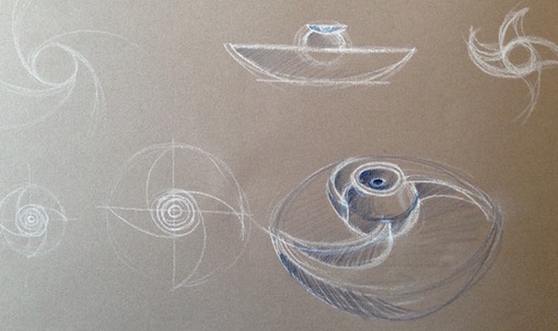
However, I do not yet have the skills to create these
forms in any of the 3D software packages that I have
explored, so this is a little frustrating. Today, some
good news, I was finally able to install Solidworks onto
new windows partition on macbook (this I completed using
Bootcamp Assistant - on Mac, installing the now free
Windows 7).
Below, I include some images of various basic 3D files
that I tried to generate - and give overall first
impressions for each, as I consider developing a form
for 3D printing.
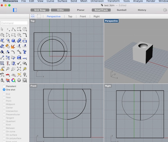
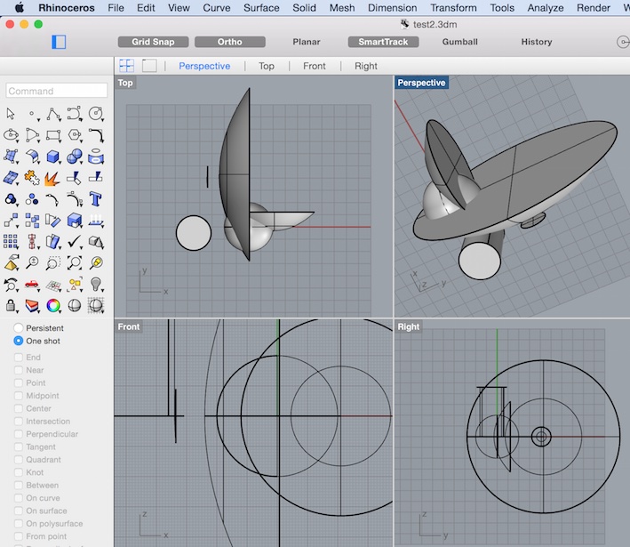
Rhino
Comments: Overall I feel that if I perservered I
could get to enjoy working with Rhino. It seems
reasonably easy to generate simple and basic forms, and
to merge them together. However, as a beginner what I
found difficult is how to control these components in
space in relation to each other. The Grasshopper plug in
is not currently avalable on Mac.
Blender
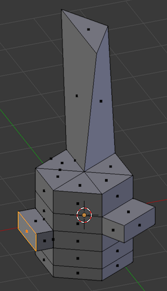
Comments: Although I did not have more than a few
hours trying Blender, I could see how this software was
very powerful and had an effective graphic interface. I
liked the 'dots on planes' feature from which you can
pull controlled fragments out of the basic form you
start with. This might be an application that really
supports a creative and visual workflow, less technical
in approach and more potential to explore forms. Its an
interesting way of thinking. It also makes apparent how
architecture has been able to evolve in the way it has
over the last few decades. Here I refer in particular to
the torsion the computation is able to make.
Solidworks
Comments: I had quite a lot of anticipation and
expectation in finally getting to have a go with
Solidworks. I was a quite surprised to see an unrefined
graphic user intercace, it looked so 'Windows' - very
clunk and click. However, in performance terms, it did
not take long to see how much control there was over
each element of the form-generating process. I was very
impressed, although it might work better with a
technical geometric approach.
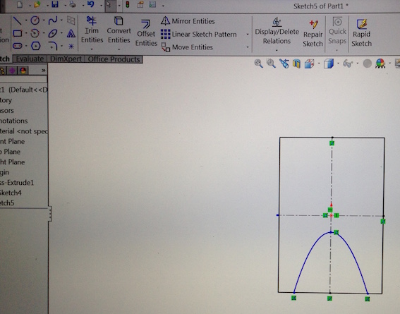
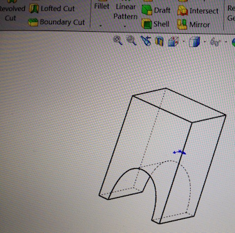
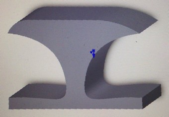
Following a demo from our mentor, I could see that
Solidworks had an effective and powerful capability to
generate a drawing / 3D model. In Solidworks, you can go
back and edit changes at every level of the the
dimensions, this was my first true experience of
parametric design. I therefore decided to choose
Solidworks over Rhino and Blender to generate the form
for my 3D design assignment.
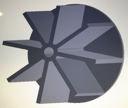
I had wanted to create a mini waterwheel that could be
placed on a spindle, or a biro, to show the power of
water. Also, this form could not easily be produced
subtractively, due to the angled fins towards the
central axis. What I found interesting was that the 3D
printer would not have been able to print this form if
it used the x-plane as a foundation plane, as it would
not have any supporting structure to undertake effective
printing paths. By simply turning the object 90 degrees
and printing on the end plane, it had all the support
structure it needed to 3D print effectivley.
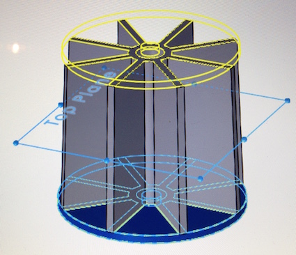
Once the form was completed and all 'dead' lines had
been trimmed and cut away, solidworks was ready to
export a .stl file. This process converts the form into
of a mesh triangles. In lower end software application,
.stl files may need to undergo a error correction
process in order to ensure the file to be printed does
not have any holes (3D printing does not succesfully
compute open faces). However, in Solidworks, and in
particular with the simplicity of the form I had
generated, Nettfab error correction software was not
necessary.
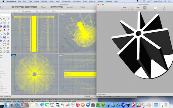
Below, the same .stl file opened in Rhino, which, after
using Solidworks did not appear to have so much control
and refinement possibility.
Assignment : Scan an object
Skanect
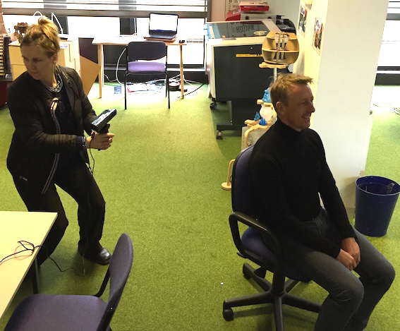
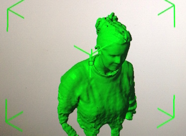
Below: using Kinect xbox360 to take a continual scan
(in series of frames/faces).
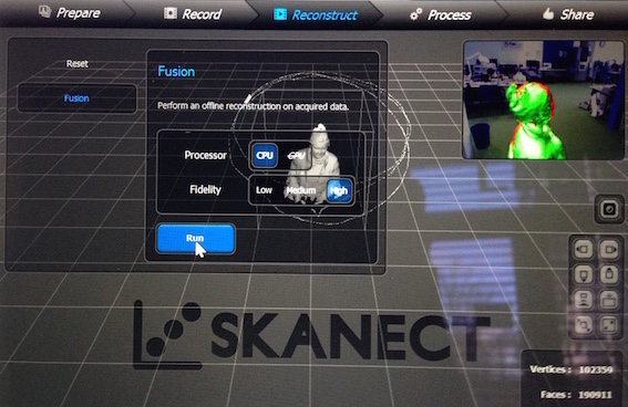
Processing the scanned data in Skanect. The file was
then exported as an .stl file, which triangluates the
form (cover form the traingles).
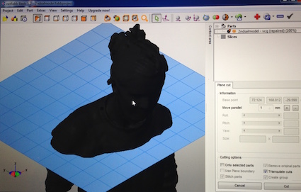
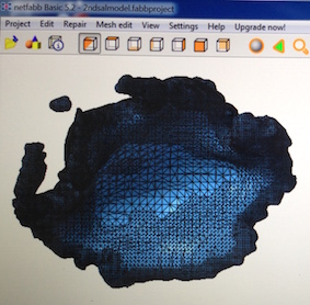
File (.stl) opened in Nettfab to correct and repair. I
checked the 'actions' for my file and no errors were
shown, therefore the object was being seen as a
watertight form with an inside and an outside (this is
critical for the 3D printing file). The form was trimmed
along the x plane and ready to be exported (as .stl) for
print.
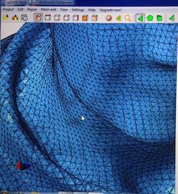
Conistent mesh covering of triangles indicating
'watertightness'. I found that there were not any
''holes" found by the software. If they are found, they
can be repaired under the 'Actions' in the Nettfab
software.
3D Printing
The 3D printing machine that was used was the Ultimaker 2.
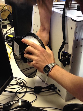
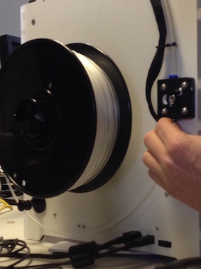
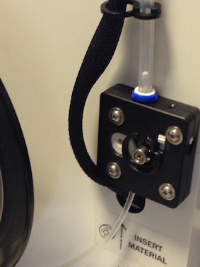
Changing the filament
The filament was changed to PLA (Poly-Lactic-Acid, a
biodegradable polymer, 2.85mm diameter, that has a low
melting point and is printable at very high speeds.
Manufacturer claim great roundness and consistency). The
new filament was placed on the reel and re-fed through
to the nozzle.
Sending to Print
File
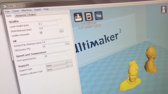
(.stl) for the waterwheel was imported into Cura which
creates
pathways for the 3D print path on the
Ultimaker. The printer was set to print
overnight. It was noted that the software is not
accurate on times! Ultimaker takes longer than
it states.
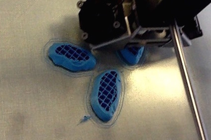
Note: It was noted that the most important
part of a 3D print is the base. If
the job does not start well, it's best to
abort and re-set. Also, where possible
you can choose to have an apparently large
solid area printed with a low FILL density,
which appears as cross-hatching inside the
scanned piece, see below.
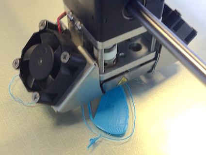
Printing from scan (route: Kinect -
Skantec - Netfabb - Cura - Ultimaker 3D
Printer):
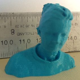
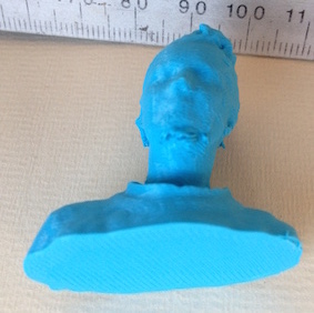
Defect under chin area shows lack of detail
captured during scanning (the neck/jumper detail
shows up well, probably due to contrast).
Printing 3D file created in Solidworks
(route: Soildworks - Cura - Ultimaker)
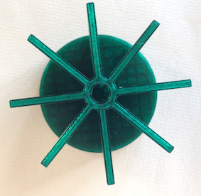
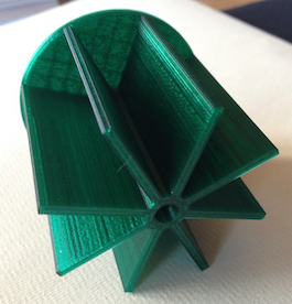
Waterwheel: I had decided to leave one side
of the design 'open-faced' so that I could see
the quality of print inside the structure. I was
very impressed with the result. It appeared to
be very sharp and consistent, with reasonably
flat surfaces (slight ridging). I understand
that the printing actually staggers along the
X-Y-Z axis; the effect of this can be seen at
this resolution and print speed.
Tolerances
The variation in print on the 2mm thick 'fins'
was between 2.06 – 2.20mm
Download larger SWmodel file here
waterwheel2.SLDPRT
test.3dm


