
CONCEPT:
Digital Mala - A wrist wearable device for buddhists (or mindfulness trainers) to count mantra recitations, moments of mindfulness and prostrations (a foundational Buddhist yoga practice).
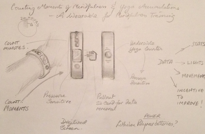
The idea behind this device is that it will help to support buddhist practitioners and those trying to develop the habit of mindfulness in everyday life.
Problem is, it's not that easy to be mindful for even just some of the time - try being mindful, present and aware even for just a few minutes, it is more than likely that distractions of all kind will arise in the mind to take you away from the present moment. However, as the great spiritual masters tell us, everything is just practice and its possible for anyone to develop mindfulness and awareness which in turn is very good for our mental and emotional health and well-being.
There is a Tibetan Buddhist saying that its a long walk to the meditation cushion. However, in any day, there are thousands of opportunities to practise mindfulness and awareness.
Functions of the digital mala:
• Mantra recitations to be counted as single counts with button presses;
• Moments of mindfulness to be counted by holding the button (for a few seconds) to start and end counting mindfulness time;
• A secondary button counter that will semi-automatically keep track of the number of prostrations or Yoga postures (ie 'Sun Salutations’).
The device allows the practitioner to be fully present in the practice or movement itself and not be distracted by the task of counting;
• When the wearer is ready to see the statistical progress of their practice, they will be able to connect the device to a PC to view their accomplishment in a graphic display.
Which Processor? AtMega Vs Attiny44
Intitially, I was very tempted to use the ATMega, as it would mean that there would be plenty of pins to accomodate 6 x leds, 2 buttons, a motor, plus Rx and Tx comms; I could even have the luxury of an external clock.
However, it became apparent that this could have a serious effect on the size of my wearable, which I wanted to be as compact and discreet as possible. Furthermore, when I really looked at the functions required with my mentor James, the ATtiny44 was just about perfect in size; offering the exact number of pins required.
Both options are compared below:
ATMEGA328
ATTINY44:
Initially, I was going to use a 2.5mm Audio Jack for Rx / Tx communications. However, I came to a stumbling block as I could not find the correct footprint for the component listed in the fab inventory. I set about learning to create a footprint in Eagle, a skill that would be useful to have given that footprints are not always available. By the time I had begun to undertake this, it was suggested that I could share the TX / RX with the MOSI / MISO pins, so the audio jack was eliminated. This would mean that I would have to create a simple adapter to bridge between the board depending on whether I was programming the board (input) or sending the data as output.
Components:
Circuit board, Electronic components (processor, 2 x button, 6 x LEDs, 1 x motor, switch x 2, 1 x rechargeable Lithium Ion Polymer battery (LiPo), charger), Silicone Rubber, Machinable wax, steel band (wide-band tape measure).
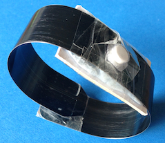
Steel band core - a bistable structure within a silicone rubber wrist wearable
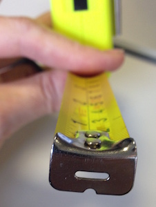
I wanted to use the simple but effective properties of steel band snap bracelets. This would provide both core integrity and a wrist-clasping mechanism within my wearable silicone device, whilst eliminating any need for an extraneous closing mechanism, which from a commercial point of view would make it more cost-effective.
The bistable properties of a steel band means it can be stable in two states - straight and curved in a coil. This is enabled by a curve that is formed into the steel at the factory.
Battery specification
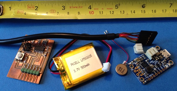
By using a Lithium Ion Polymer battery, I would be able to have a reasonably thin, light, portable and reachargeable power source , with enough power to charge the device for a day's usage.
(image from Adafruit):
Estimated Bill of Materials (BOM) to produce 1 x clear silicone prototype of D'Mala:
Fab Lab Inventory components :
Copper clad board
Electronic components:
ATtiny 44processor
2 x button
6 x LEDs
Slide switch x 2
Machinable wax to create mould
FTDI cable and connectors
Estimated Fab Lab components COST: £6-8
Non-FabLab Components:
1 x rechargeable Lithium-Ion Polymer battery (LiPo)
(4tronix.co.uk): £7
Vibration motor (fastcomponents.co.uk): £1
Charger (4tronix.co.uk): £6
Silicone Rubber ("Sorta Clear 37" by Smooth-On -
supplier Bentley Chemicals UK): £6-£8
Estimated Non Fab Lab components COST: £ 18 – £20
Total ESTIMATE to produce one clear silicone working prototype: £26 – £30
Creating a flowchart for device operation
This was really helpful to try and help me visualise all the different states that would need to be included in the code to help for both function and programming:
VERY Rough Prototyping
By mocking up rough protoypes, it helped me to eliminate or select different possibilities, work out where to best place buttons for different functions and to see how materials might behave.
Exploring the ergonomics
I wanted to explore how the user might actually interact with the device. I wanted it to be as comfortable and strain-free as possible. After all, it was a device that would require repeated button clicking for certain count functions.
To help me with this, first I cut out a strip of cardboard to the rough dimensions I imagined would accomodate the components. I then marked my thumbs with colour (left and right) and established a comfortable hold on the strip. The thumb print, depending on whether I used left or right hand left a different impression. I felt it would be good to reflect fair use for both left and right handers. This shaped my initial thoughts on the design and look of the device, as shown below:
Electronics
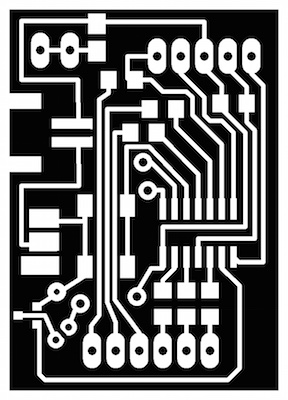
As it was very important for the device to be as compact and discreeet as possible I set about trying to get all the components on a board size 28mm X 40mm, as shown below. The second button would not be required to be on the board itself but at the end of the strap.
I chose to use individual solder pads to make a custom FTDI connection. This helped me get all the parts on board. I wouldn't want to give the impression this was easy. This was a mammoth task and took 2-3 days of manoeuvering!
The best possible board design I managed to get, would still require that 3 connections would have to be soldered over the top of the board with insulated wire.
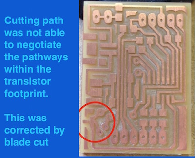
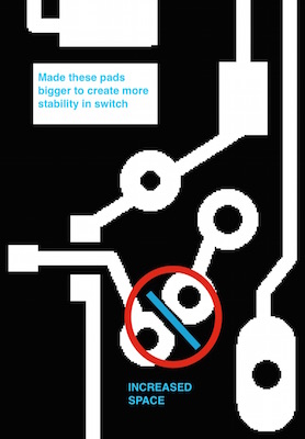
Some finer details had to be refined in Gimp, to make sure spaces and clearances were going to be sufficient. The board was then ready to mill on the Modela.
Moulding and Casting
I wanted to see how all the components mights works together, to get a sense of scale, flexibility and to highlight any problem areas. I needed to make something quick, and at home, so I sculpted some plasticine, coated with cling film. I thought the cling film would serve to restrict any incompatibility between materials and also to create a better mirror-like finish.
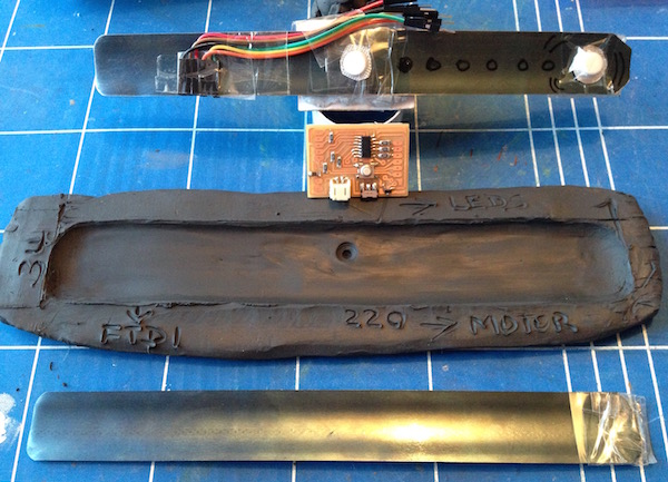
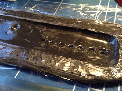
Having learnt from the Moulding and Casting Week, I had wanted to try and have more control to get the liquid (high viscosity) material into detailed areas quickly whilst reducing the chances of trapping air bubbles. I used the principle of the piping bag. This worked really well as the material could be directed with control and pressure.
Things were going so nicely that I forgot to embedd the steel band! There was also a significant consideration highlighted at this stage. The steel band has a curve alongside the centreline. For the device to bend in the right direction, the curve would have to face down, which would risk trapping a lot of air in the very core of the device - very undesireable. So on this occasion, I decided to slide the steel band into the oomoo, the wrong way up, otherwise air would surely get locked in. This meant that the buttons would be on the wrong side but at this stage it was more important for me to see the steel core bending whislt embedded.
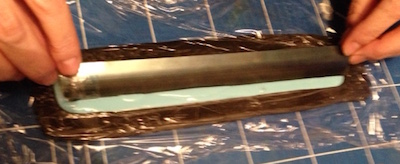
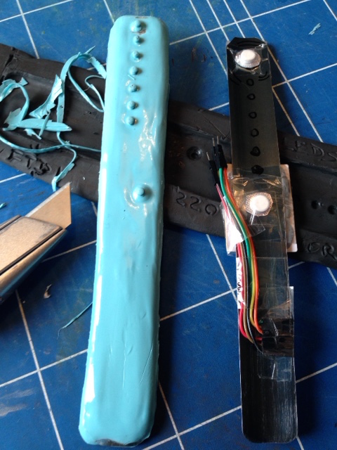
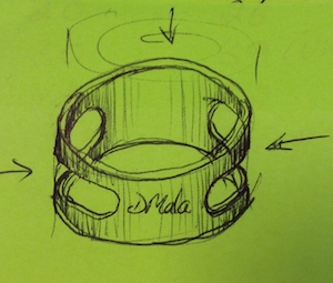
On seeing and interacting with my first cast, I developed an idea for a protective travelling case for the device (when not being worn on the wrist).
The most stable position for the strap would be when coiled. The design is shown in the sketch below. Two elliptical slots, allow the user to press the silicone coil inwards to release it out of it's friction grab within the case. This would be a good project to use the 3D Printer:
Back to the Electronics
Checking continuity on the board, and so far, connections were good.
Next it was time to solder the insulated wires (that could not be routed in Eagle) and add all the off-board connections. I found it helpful to have a clear picture of the connections that I would be soldering, as shown in the image below. I kept the prototypes nearbye so that I always had reference for scale and how long wires/cables needed to be.
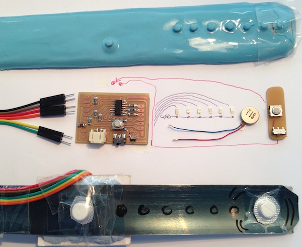
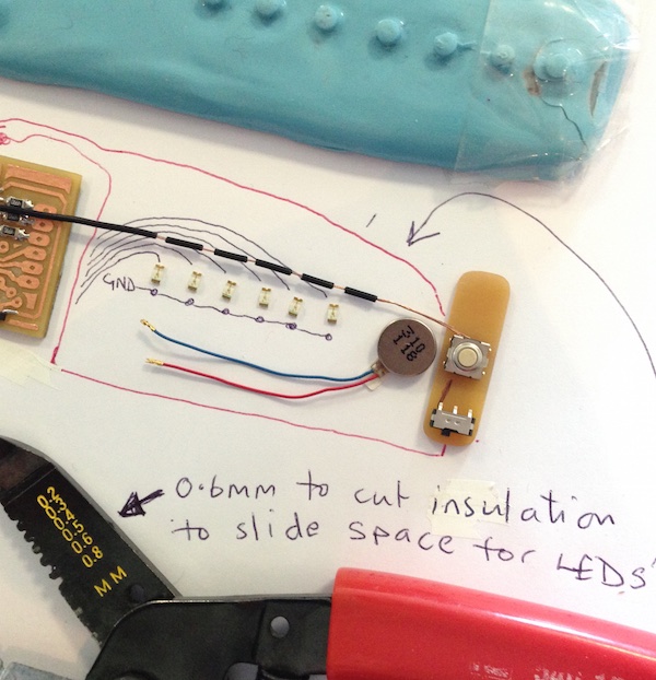
My mentor James showed me a great way to connect all the LEDs in an organised line, and provide the ground line on the other side (see below):
The device would be programmed via an FTDI cable. As the Tx and Rx communication lines would be sharing the MOSI and MISO, the ftdi cable had to be reconfigured to suit (shown in sketch below).
Testing the board for the first time
So, before going any further (adding the motor and second off-board button), it was a good idea to test the board.
I connected the Fab ISP, power from the miniUSB and opened Arduino to choose the Attiny44 board, clock (8Mhz internal), programmer and port. I was quite surprised that the bootloader burned without any error, but that's what it did. A good moment.
Then, I loaded the example code "Blink" in Arduino. I wanted to check each LED in turn, so I changed the pin to match the Arduino pinout in the code. Error.
With closer inspection, all LEDs were oriented the wrong way round - I'd misapplied my logic for the positive and negative. Ouch.
So back to the soldering station to spin round LED1 to test. Having done this and on re-doing the test, the LED flashed exactly as the code requested. Relief. I went to de-solder and re-solder them all. The 6 LEDs flashed successfully in turn.
There was one unexpected behaviour: LED 6 flashed for half a second just at the beginning, before any one of the other LEDs flashed. This was likely to be the programming pulses, and that this would not happen post-programming. So all was good so far. I was now happy to continue to solder the additional off-board elements with wire links.
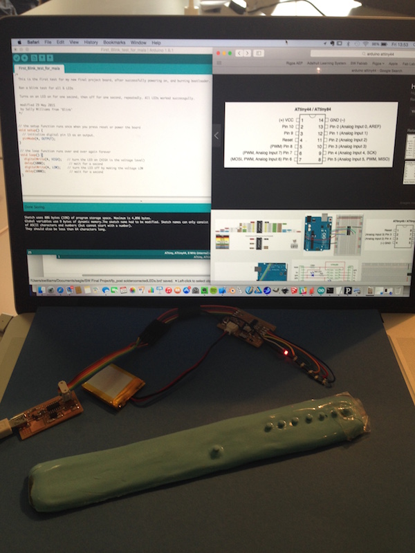
Having soldered and connected the second button, second switch and motor to the board, a poor connection showed up. This was revelaed as the motor just statred up on its own without any command. After testing under gentle movement, it was noted that when the transistor area was pressed a little, the motor state would change (ie it would start or stop or vibrate at higher frequency). This suggested that the motor was receiving fluctutating power and only intermittently, revealing a short circuit. The transistor area of the board was one of the narrowest of routes, so this will need attention. I had created a route underneath the transistor, so I may have to create an over board link instead.
Before setting out to test the function of each of the buttons and motor with code, I made it easier for myself by creating a quick reference pin chart so that I could refer to it as I tried simple code tests.
Functions PIN CHART (for quick reference when coding):
Testing the function of button A and Button B and the motor with the Arduino IDE
I adapted the basic code examples found in Arduino libraries to test each of the buttons and the motor. Whilst this showed the code to program the board successfully in each instance, there did appear (in behaviour) some areas of instability and sensitivity. Further visual inspection checks were made, and the transistor was replaced, however, the board was still not responding with 100% power to 100% task. The image below shows the working code that was used for this testing.
Defining Inputs and Outputs
As some of the pins on the ATTiny 44 were multi-functioning, some lines were being shared during processing, and whilst some charge residue may be remaining in the circuit, were creating ambiguity, appearing like poor connections. However when all inputs / outputs / pins were defined in the code set up this was all clarified and the board showed 100% engagment with each test command. See definitions below:
100% Button, LEDs and Motor response:
3D Printing of case to tranport and protect digital mala
Here is the result of the first 3D printing attempt of the mala case, produced without supportive material capability, on a custom-made 3D printer in Manchester:

Second mala case design 3D Printed by Dimension:
As is shown in image above, the 3D printed failed for lack of supporting subtractive material. Therefore, as the slots were central to the design, I printed the case on the Dimension (sst 1200esDimension sst 1200es), where supportive material is printed and then dissolved in a solution post.
Below right, the support material is shown in the set up:
Based on 21 cm3 model material and 12 cm3 support material, the cost of material for this design would be approximatelay £7-8, whereas using the first 3D printer (custom made in Manchester) would have cost £1.50 (but this was proven unable to 3D print the arch area successfully).
Computer Aided Design - Drawing the digital mala design in Solidworks
Milling the machine wax to create the mould for the silicone
The settings for the milling are shown below.
Tools used: 3mm Flat End Mill; 1/32" Ball Nose Mill
Surface detail (Mantra of Compassion in Tibetan script) shown below was converted from a pdf file, and added as a bitmap trace in Partwork 3D:
The overall quality of the milling was very good. There was a very subtle 'scratch' surface defect that showed up around the flat areas where the travelling end mill was recovering from z axis increment - shown in the close up below:
Back to the Electronics - developing the second board - incorporating improvements
Currently I only had one working test board. Having been through the process once, I could see small ways in which to make improvements in the wiring and to plan it as efficiently and as slim as possible.There was a real risk that in moving the board around during testing / coding that the copper wire / solder joints were being fatigued and were in risk of breaking off.
Scale drawing to guide placement of components into mould (6 x LEDs, Button A & B, Motor):
Finding ways to clamp the wire when soldering the fiddly LEDs to try and reduce any twisting in the wire, so that they would all face the right direction:
Incorporating improvements; removing 'kinks' in wire and utilising ground at other points to reduce wires on board:
Testing the second board
Once the second board was completed, I set about testing and programming the board with James.
The photo below also shows the adaptor for the Rx / Tx comms in and out of the board:
With various board test routines, all the essential functions outlined in my intital plan for the device worked successfully. This included haptic feedback when a basic button press target was reached; all 6 LEDs worked to show which count selection was being counted, and blinking to confirm that time mode was selected (counting minutes instead of button presses). With these functions in stable working order I was ready to cast the second electronics system once I'd completed my mould tests.
Mould development
In my first cast I had forgotten to include the required depth to contain the 3mm LiPo battery. However, the inclusion of the battery would mean that the wires of the battery would have to emerge from the main body, bend and return back to connect with the board within the body (to give power during use and charging during programming).
I experimented with adding a second makeshift mould (out of cardboard) in the middle of curing to build space for embedding the battery:
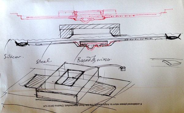
Following this test, I decided that I would scrap the inclusion of the battery and use it externally for the prototype.
There was quite a few other considerations to bare in mind during the moulding process. For example, for the strap to bend in the required direction, it was critical for the curve of the steel to be set in the direction shown below (with the curve steel edges facing up in same direction as buttons).
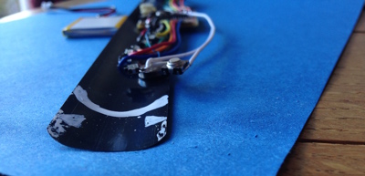
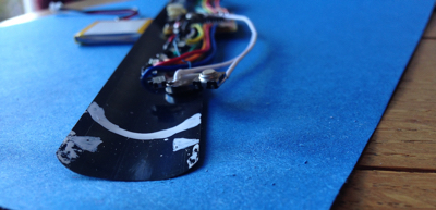
Below, I simulating the effect of the wires and board to see how it might affect the bend of the steel band:
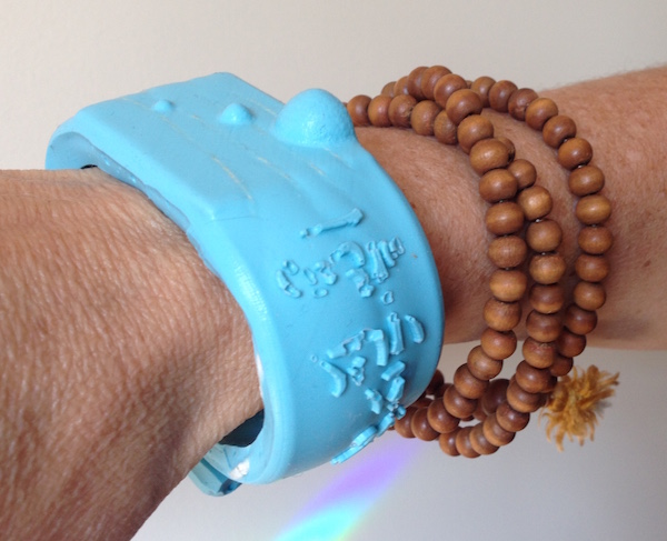
As shown below, I designed the device around the constraints of the electronic board and components; the battery connector was particulary obtrusive but totally necessary. I designed a series of spheres: the largest to house the connector (and in this way, reducing the impression of the depth of the central body); the seond to house the counting button; I introduced a third dimple simply to create a sense of rhythm in the spheres - and a homage to traditional mala beads.
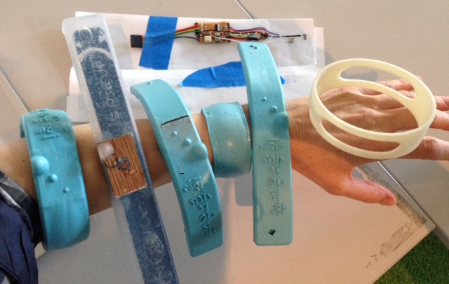
Transparent vs Opaque SIlicone
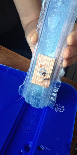
I produced a number of moulds. The one below on the left was made with "Sorta Clear" Liquid Silicone. The advantages to this silicone was that it was semi-transparent and would improve the luminescence of the LEDs. Also it was interesting to see the placement of the electronics and behaviour of the steel band embedded inside. This particular prototype proved to be much too thick, with the steel finding it impossible to bend uniformly due to the board thickness (mocked here by a 3 mm thick plyboard). I began to concede that the steel band would not bend and clasp with a square circuit board embedded.
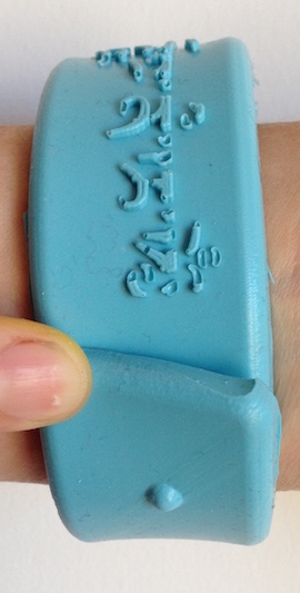
Below, a traditional mala is shown next to a D'mala casting. The image on the right shows the inner wrist button for floor pressing (counting prostrations).
Casting the actual electronics
So far, all the prototypes did not include any electronics. When it came to casting my actual first programmed and working electronics system, there were a few things I had to consider. I had decided that I would not embedd the battery in the prototype, as it made everything too cumbersome. I would connect the battery as an external unit for the time being. To make sure that silicone would not fill voids (such as the battery connector cavity and ftdi connectors) I filled them with blutack. It worked well, and as blutack sticks to blutack it was quite easy to remove.
Having mixed the 2 part liquid rubber solution, I used a piping bag to place the first layer. Then, I had to try and place the 2 buttons and LEDs as accurately as possible in their respective mould recesses in the cast. With experience from the earlier casts, I felt the silicone would begin to hold the loose components in place after a short while. Therefore I used toothpicks to hold button B and the switch in place for about 10 minutes.
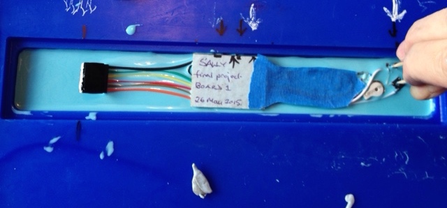
Once I had the electronics curing in position, I was able to add the remainder of the silicone into the mould.
Curing time = 1.5 hours
Post-casting tests
I removed the blutack, cut away any excess silicone and connected the power and cables to check connections post-casting.
Everything connecting well.
I pressed the buttons to test the code. As expected, a button count of 5 activated vibration alert form the motor and lit LED 1. This was a very satisfying. All the LEDs worked apart form one (this was explained by a resistor I found on my work bench). However, the opacity of the turquoise silicon made the luminosity of the LEDs virtually ineffective. Fortunately, the LEDs that I used in my second electronic system were much more powerful with a greater lumnens value. Nonetheless this made me decide to cast my second board in the Sorta Clear so that the lights had a greater chance to be more effective.
Arduino test code to run to serial monitor
In this test, the second electronic board was programmed to discern 2 different kinds of button press - single presses and button hold press and to send 7 unique sets of data (reflecting simulation for 7 days of the 2 kinds of data) to the serial monitor; this was a succesful output test, as shown below:
(For fuller comments - see code file at end of document)
Processing
Next, I could return to the basis laid out in the Interface and Application week, to use 'Processing' to convert the data from the device into a meaningful graphic display for the user to see progress in mantra recitation or mindfulness training (again, I could not have done this without the help of James Fletcher - a legend).
The visual graphics below appear (virtually live) from direct button presses into the electronic board:
(For fuller comments - see code file at end of document)
Final Casting
With the input and output code now working, I felt ready to undertake the final casting for the second electronic system. I had decided to use the clear silicone, so I could see how the electronic detail behaved inside and to improve luminosity of LEDs.
Planning
I took care in planning how I would secure the buttons and board in place before I prepared and mixed the liquid silcone:
As shown above, I held the button and board in place with a few props until the silcone started to cure. Then, I added the remainder of the silicone to cover the components. Trying to take care not to overfill:
Failings of design
The only area where there were clear failings in the design were the methods I trialed in securing the mala around the wrist.
Steel band clasp - Failed
This failed due to the size, straightness, depth and strength of the electronic board, prohibiting a consistent bend. As the steel band is bistable, it cannot be both flat and curved. My design was asking for too much flexibility around the board. The clasp would not snap around the wrist. I still envisage that the steel band would work well with felxible electronics - a solution that would be ideal for future development.
Magnetic clasps - Failed
I experimented with several different magnetic solutions.
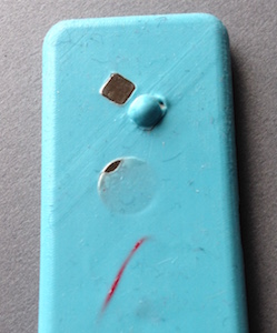
I tried embedding small, but powerful (1kg pull) magnets. The problem here was that when the magnets were embedded in the silicone, the flush and direct magnetic contact required for the 'pull' to be effective was significantly reduced to the point of being ineffective. However, if the magnets were embedded too near the surface, the silicone was not strong enough to keep them contained and the surface gradually fatigued and they fell out (see image below).
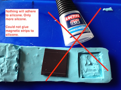
As a last attempt solution before submitting my final project, I tried to glue polarised magnetic strips, on the outide surface of the silcone (so that at least the magents could be in direct contact with each other). However, silicone is non-stick, and I have not found a flexible adhesive that has worked). Online comments suggested silicone adhesive would not work either. Even if it would work in the short-term, it would not be an effective long-term solution as the magnet would pull itself off over time.
Final Cast removed
Below, all connections for inputs and outputs are shown with final cast (with adaptor connection on right):
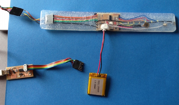
I was happy to see the D'mala flexing well and stable whilst testing:
Evaluation
As outlined in Application and Implications in week 15, my final project would be evaluated by the questions shown below; and this time I can include the findings:
• Does the digital mala count, record and function as a counter (in reliance of a PC to output data)? Yes
• Are the counting functions and modes working as expected? Yes
• Does the vibration feedback provide alerts as and when expected in the functionality? Yes
• Does the silicone encased steel work effectively as a wrist clasp? No
• Does the app effectivley communicate the data to the user? Yes
And again, the end of one road, the beginning of another...
Thank to Michael, James, Simon and of course, Neil.
FINAL PROJECT DOWNLOAD FILES
ELECTRONICS
Eagle:
Schematic
Board
Files to mill board:
Traces
Outline
CAD
Mould
Solidworks file
stl file without script
3D Printing
D'mala case stl file
CODE
Arduino
Arduino code:
Inital function test code
Final Project Arduino Code
Processing
Processing Code:
Code for graphic visuals to display output data
Background image
© Sally Williams June 2015. All rights reserved.