The output devices week was really nice. Once motors start moving, you get a hint of where all of the effort put in the circuit boards might lead to. I designed two boards this week: a board for a stepper-motor and a board to control an LCD-display. I might want to use both in my final project. The LCD-display to give feedback in words and I would like to use the motor to give physical feedback.
add an output device to a microcontroller board you've designed and program it to do something
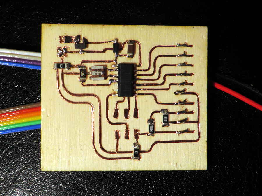
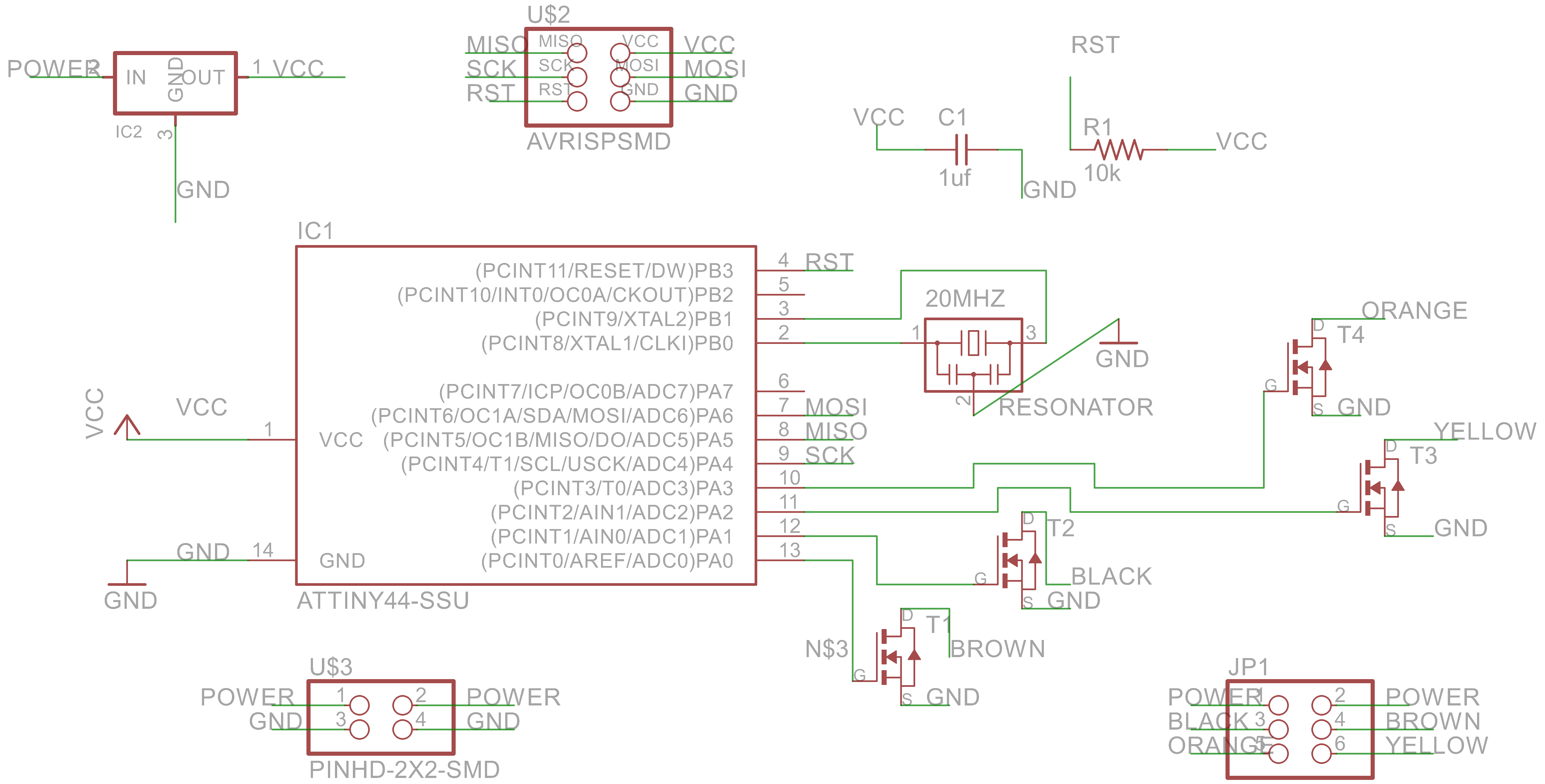
I designed a board for a Stepper Motor in Eagle based on Neil's example. In the first design I added a FTDI header and resonator so ensure the serial communication would work properly. Afterwards I removed the FTDI-header again, to make routing in Eagle easier and I wasn't going to use anyway. I left the resonator in the design because the pins on the IC where free anyway and it didn't matter for routing the traces.
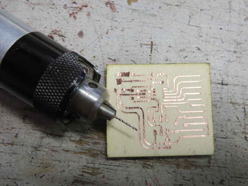
Designing, making and soldering the board went fast and easy. Except that I blew up the regulator because I was in a hurry, since the Lab was closing. This was easy to fix the next day. When I find the time I'm going to write some programs myself to control the motor, but for now I uploaded Neil's C-code and the board is working.
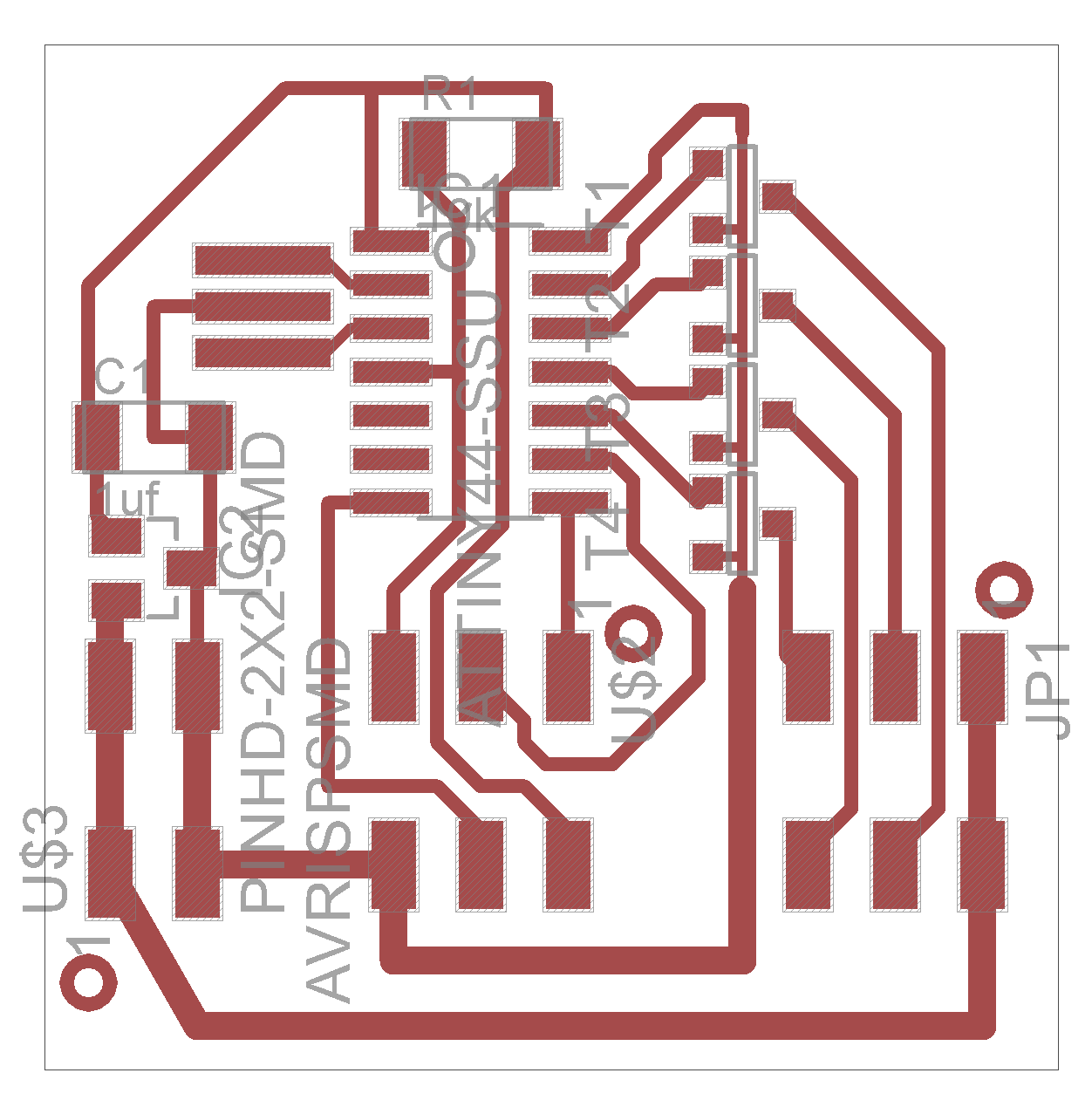
I also made a board to control a LCD-screen and I used the vinyl cutter to cut the traces in stead of the milling machine. The LCD-screen is not working yet though. I finished the assingment for this week with the stepper board and had to go on with the next assignment, but I learned a lot about the vinyl cutter, which is documented below. The board is working properly as far as I can tell, but I probably blew up the LCD-screen due to a stupid mistake in the schematic. Somehow, I connected VCC and GND to the wrong wires/headerpin the schematic and that might have killed the LCD-display.
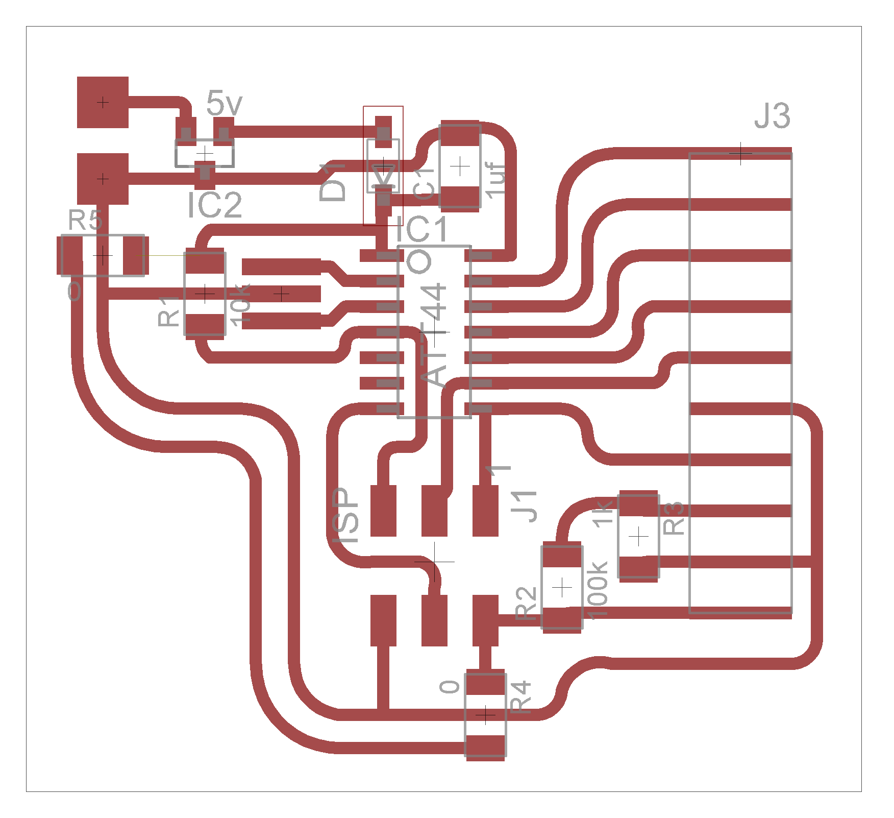
I made this board with the vinyl cutter in stead of the milling machine, because I wanted to get to know that machine better. I was a bit disappointed how the pads from last week's assignment turned out and decided I could do better than that. I checked other people's documentation and tried a few different things, because cutting out a circuit board is a bit tricky.
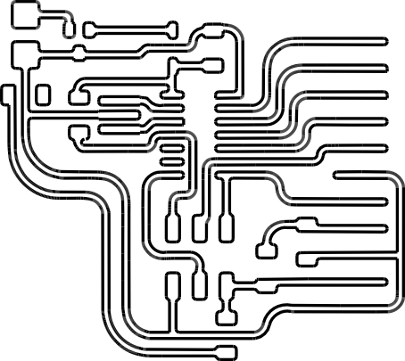
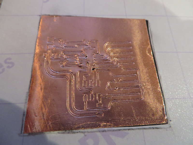
I used 24 mil (around 0.6 mm) as width of the traces and also as clearance between the traces. I didn't use the auto-router function in Eagle, so I was in full control of the routing. The copper foil tends to twist and come loose when you have sharp angles in the design for the vinyl cutter. I tried to avoid sharp corners in the traces, to do this I placed the components a bit further apart than I would usually do. After finishing the lay out in Eagle I edited the traces in Rhino to round the corners of the pads.
vector file edited traces Eagle files LCD board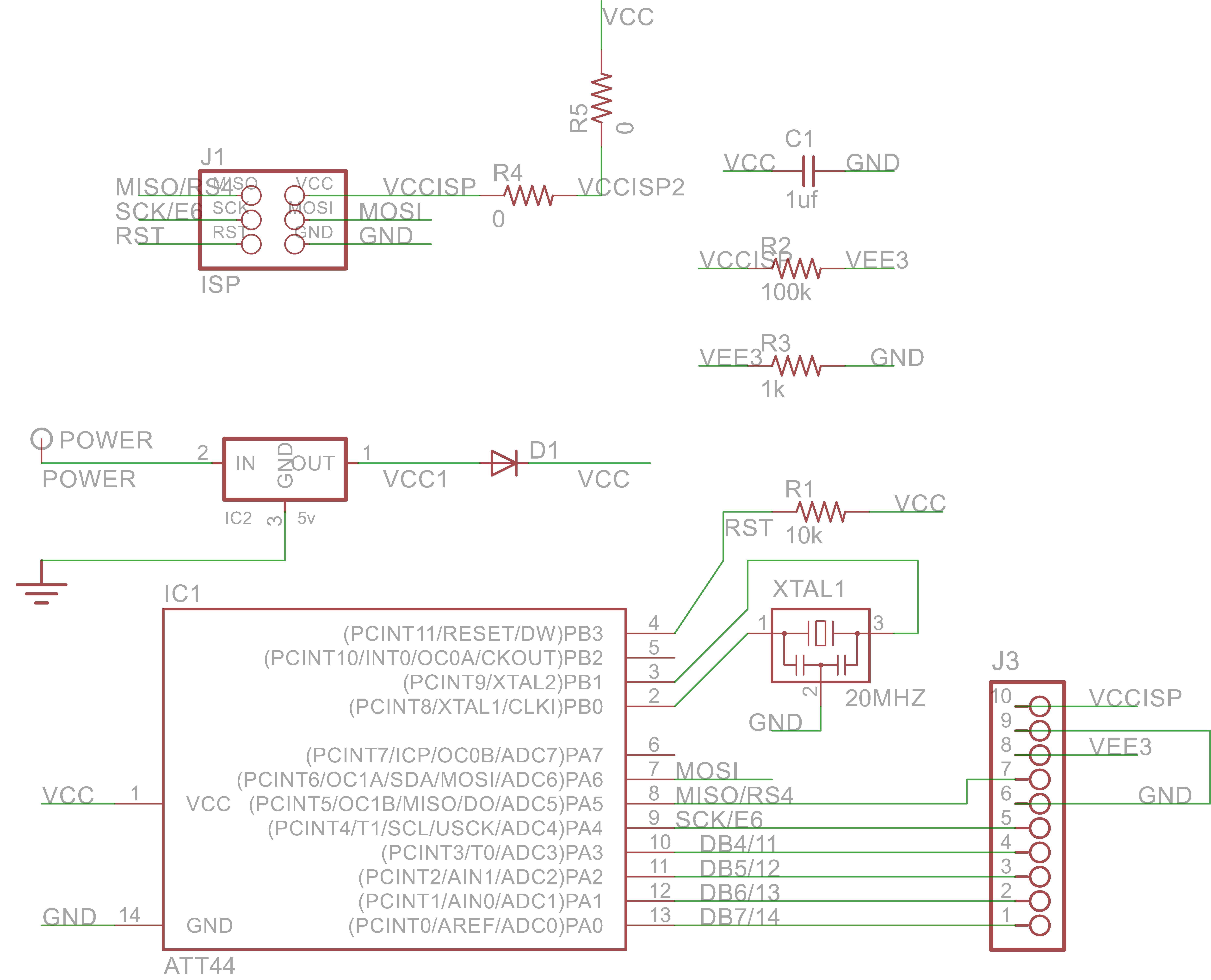
So far so good, but now for the tricky part: cutting the copper foil. I used copper foil on a roll. When I was figuring out the right setting, I encountered a challenge. Either the copper wasn't cut properly when pressure was to low, but using the higher pressure the traces came loose immediately. The copper foil doesn't stick much to the paper it comes on, so it is easy to transfer. BUt with small parts, such as the traces, the cut copper comes loose of the paper and the knife starts dragging it around. This leaves a mess of half-cut, scrambled copper foil.
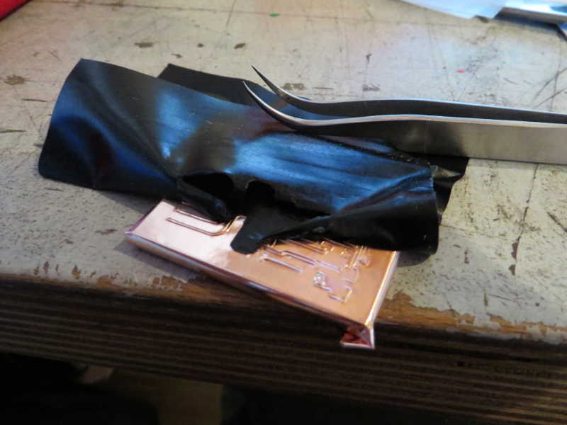
After this I tried to transfer the copper foil on another material before cutting, using the transfer paper. I transferred some of the copper foil on a piece of vinyl. The copper sticks better to the vinyl than the coated paper, but I hoped it didn't stick too much so I could still remove it from the vinyl.
In the end I managed to pull the copper from the vinyl with the transfer paper, but the glue of the copper foil stuck to the vinyl so the traces I had didn't have any glue on them. This meant I couldn't transfer them..
In the end what worked, was cover the copper foil with vinyl, flip it, remove the paper of the copper and cut it with the sticky side up. Settings on the vinyl cutter: force 80 and speed 1cm/s. The bed of the vinyl cutter at our lab is starting to wear out a bit, so I cut on the right side in stead of the more used left side. I transferred the copper traces to a base plate of plywood.
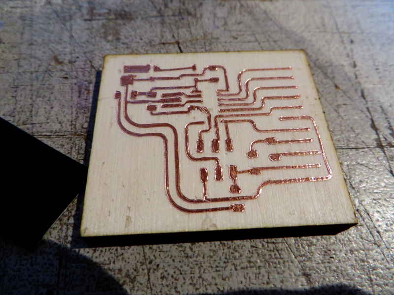
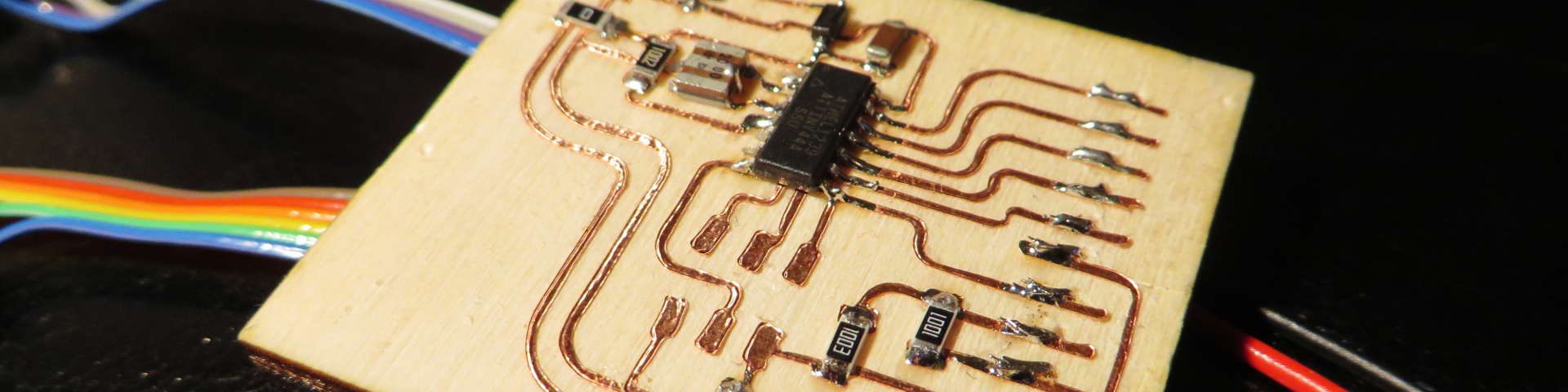
Soldering itself wasn't that hard, the only thing is that sometime traces move a bit, because the glue doesn't stick anymore when it gets hot. I didn't put on any header pins, because they could rip up the traces when force is applied to them. For the ISP I just left the pads and held the header pin in place when I'm programming. For the power supply and the connection to the LCD I drilled holes and soldered wires from the bottom and glued them in place. I did this on the bottom of the board for esthetic reasons (I didn't go through all the effort to cover the board with hot glue).