 FABRICIO SANTOS
Week 8 - Computer Numeric Control
Learn to make something big with the milling machine.
DÉPLOFLÉX
Designing Living Hinges: FLEXURES / JOINTS / DÉPLOYÉ
|
Flexures, joints and déployés. |
As Neil recommended, first develop the building blocks and then make the larger project:
1º Make a single beam to get a feeling for stiffness and strength Vs length and thickness.
2º Make a joint between beams.
3º Finally make an array of them.
|
 |
 |
Flexures. |
Joints. |
Déployés. |
Flexures
I started testing small beams and joints (design > mill > test).
|
 |
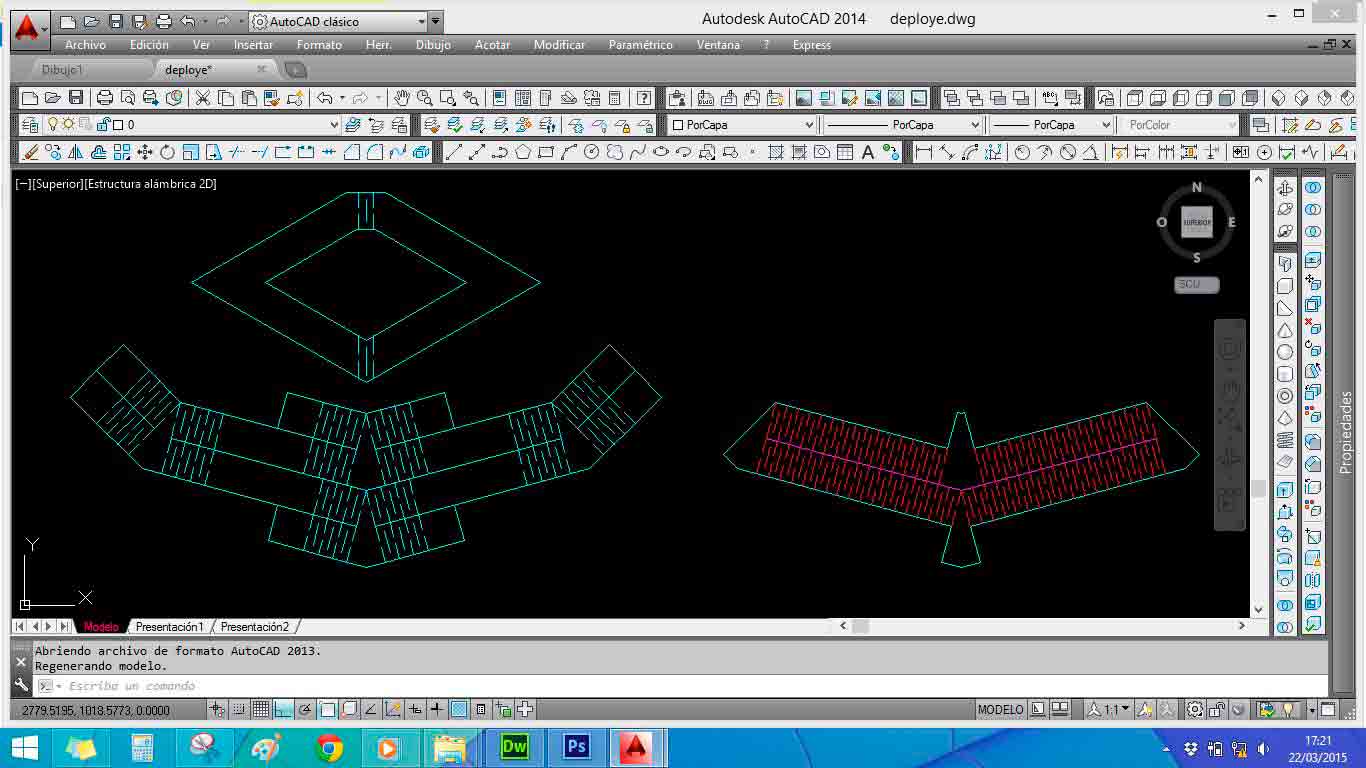
1 Designing pieces in AutoCAD. |
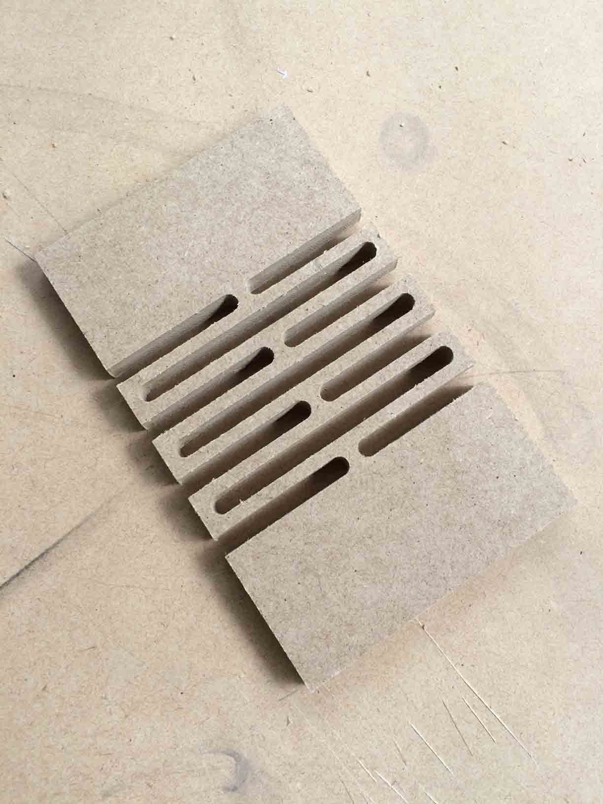
2 Flexure milled pieces. |
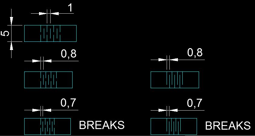
For this kind of cuts I need to do only a profiling strategy to send the vectors to the cnc machine. In this case I chose to run the tool trough the vector (nor in or outside the line). In this way the width of the cut is striclty the same size as the diameter of the tool, 6mm in my case, that is the same amount of material I lost while milling.
|
 |
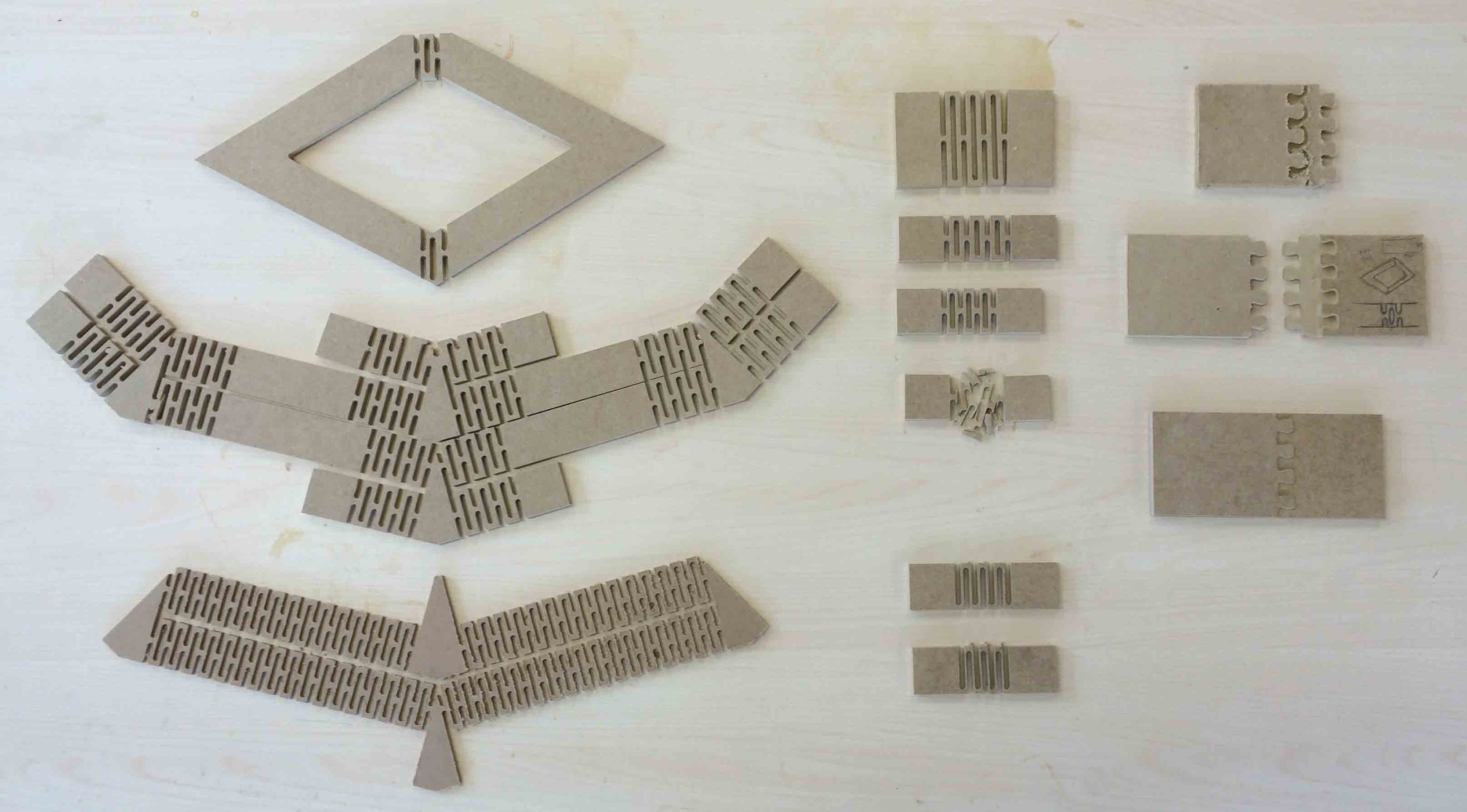
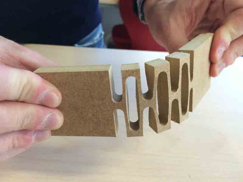
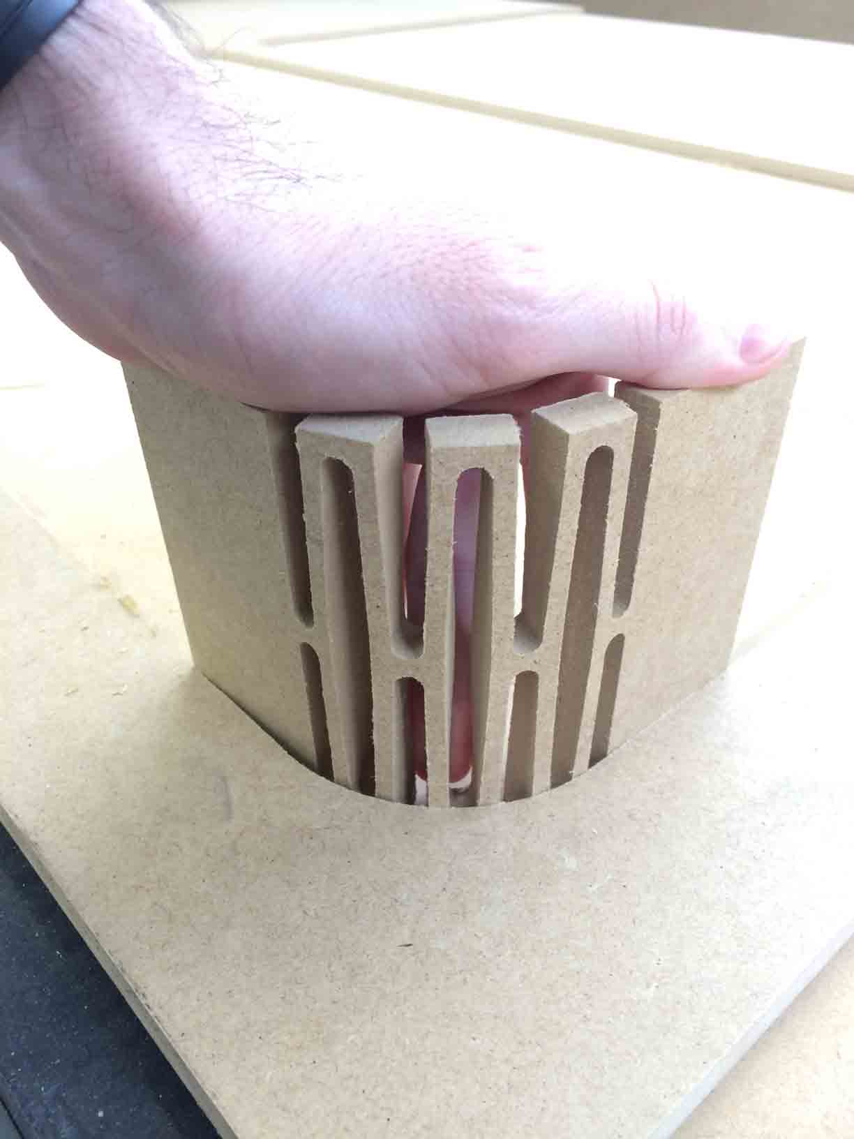
3 Flexure déployé design. Bending test. |
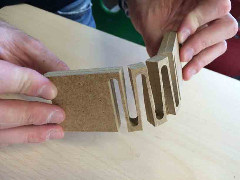
3 Flexure zig-zag design. Bending test. |
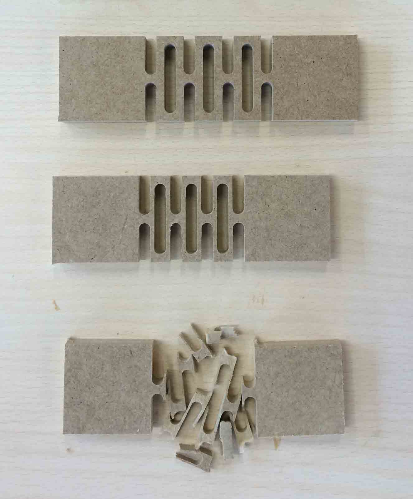
I have been working with flexures in MDF of 10mm thickness testing pieces of 50mm width, so the cuts length cover the 80% of the width. I have cut it with a 6mm tool so the remain material have only 4mm of thickness.
Comparing déploye flexure against zig-zag flexure with the same spaceship between lines (2mm) and thickness (10mm), we find that déployé one bends harder till 60º and zig-zag one bends easier till 90º or more.
But the zig-zag flexure presents too much torsion that is not very good in the way I am working.
|
 |
MDF wood of 10mm thickness. |
Bending wood 90º. |
As far as I am concerned in flexure designs as longer the cuts are as much the beam would bend in the opposite direction. So material´s width matters.
Joints
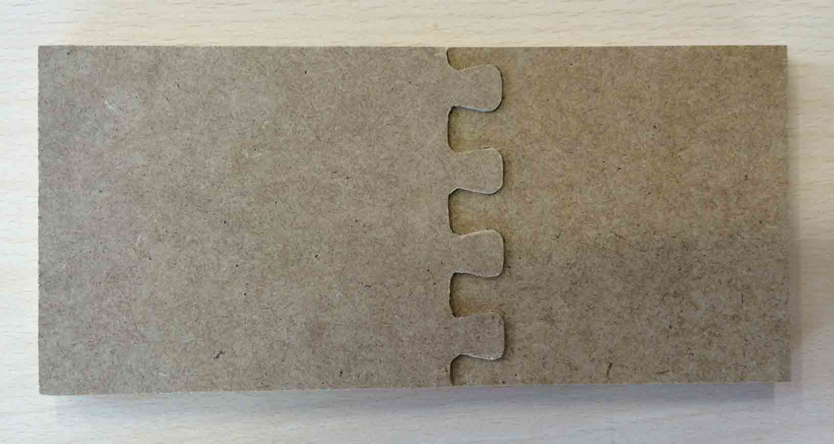
Looking for examples I found a kind of thesis in joints called 50 Digital Wood Joints by Jochen Gros and I decided to work with T_015_2 one.
|
|
Separate pieces. |
Joined pieces (glue was not necesary). |
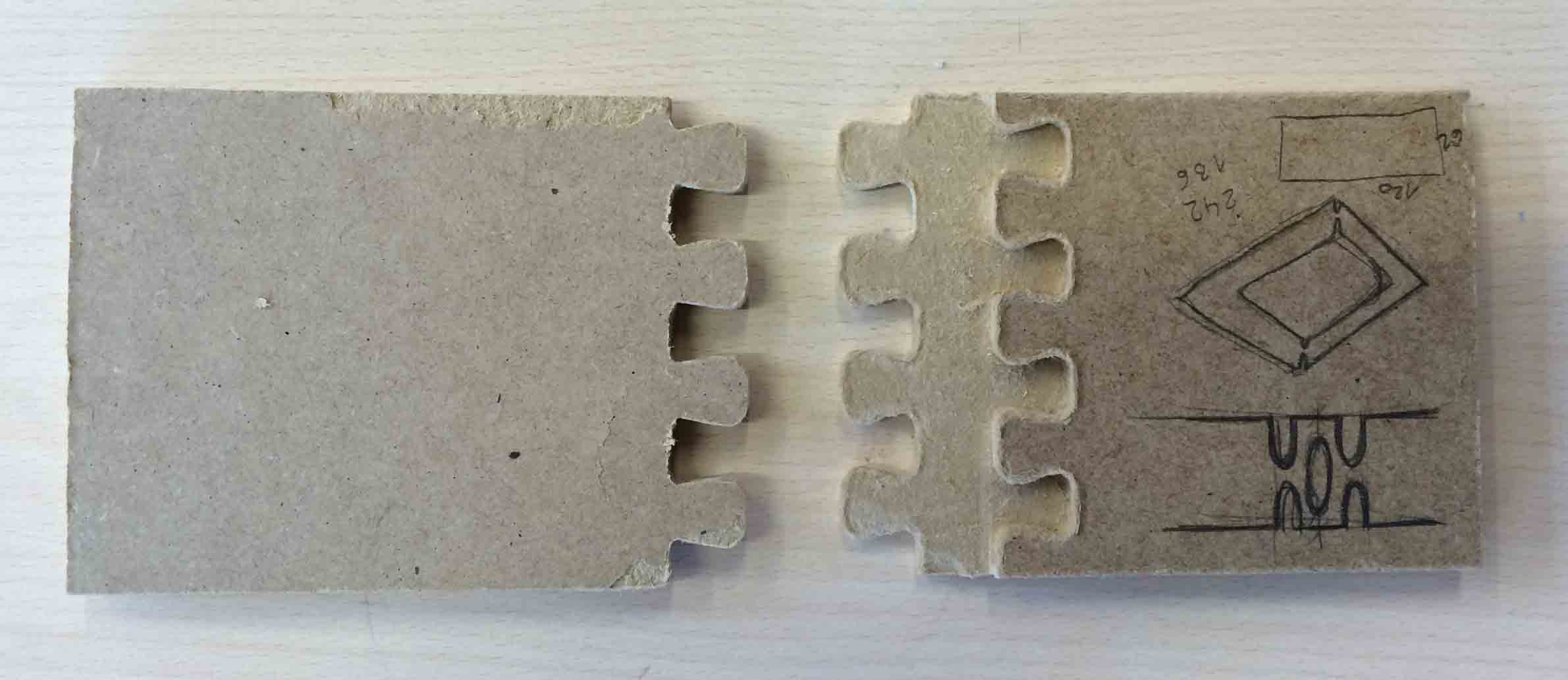
For this kind of joint I need to do two strategies to send the vectors to the milling machine: first a pocketing routine to remove the material of the first depth and then a profiling routine to cut the boundary of the piece.
Déployé
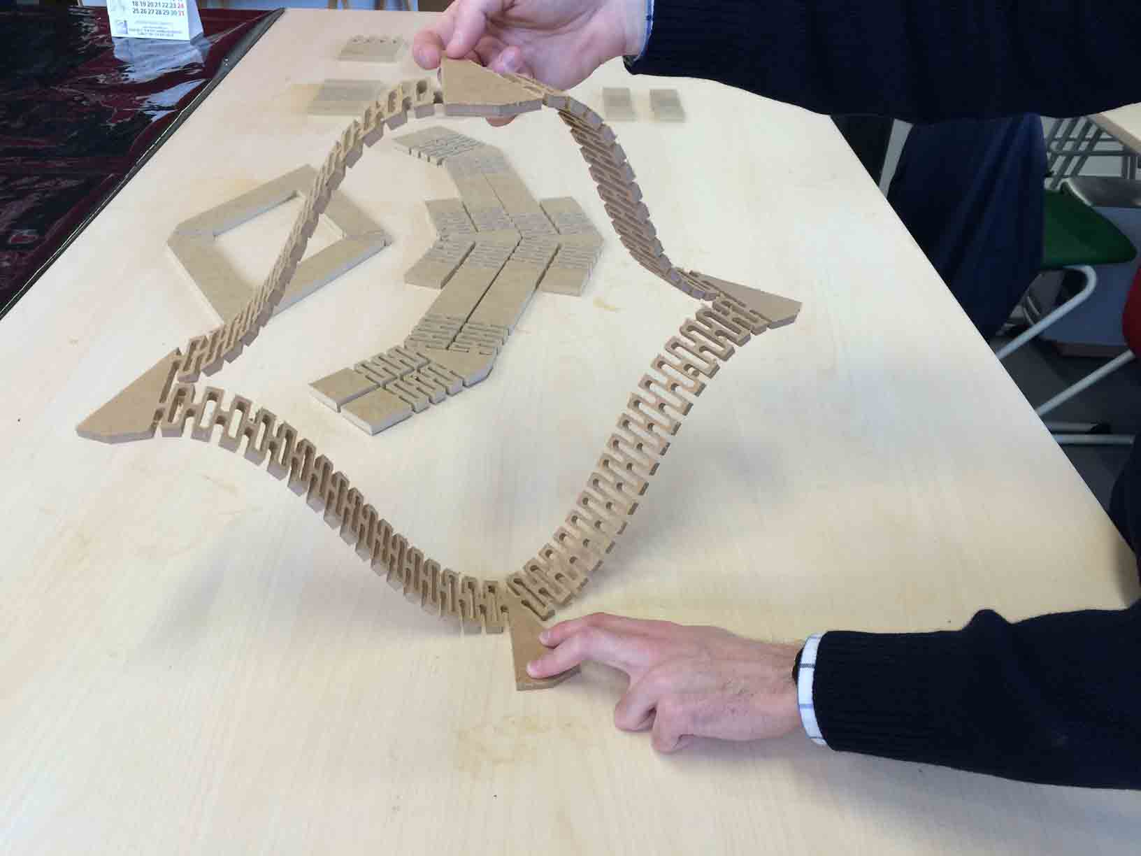
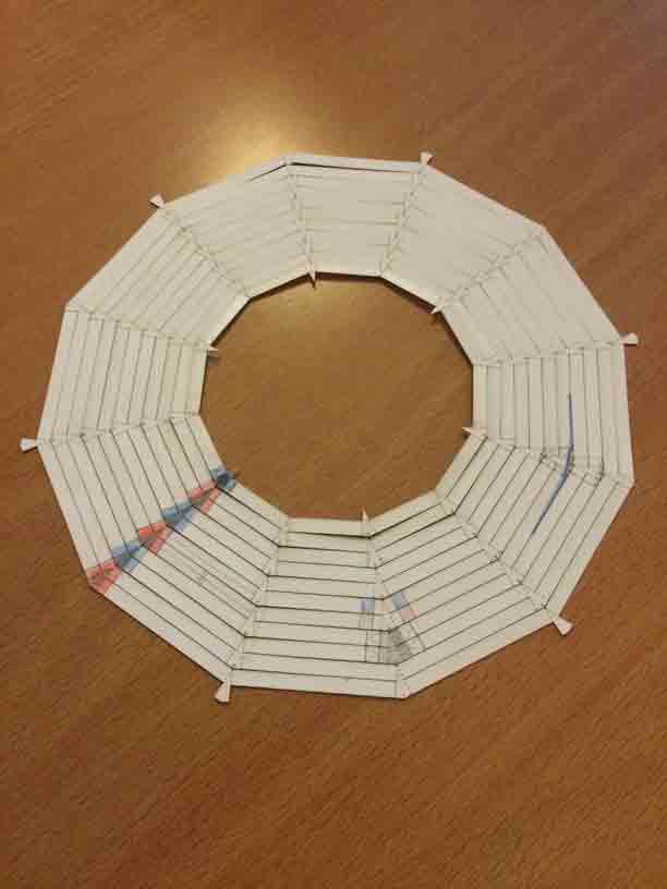
I tried to make a big deployé dome with living hinges in a material with some thickness. Or what is the same a flexure dome made by concentrical flexures wich lift thanks of radial flexure hinges.
|
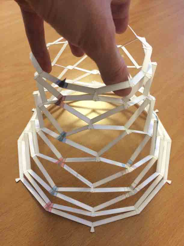 |
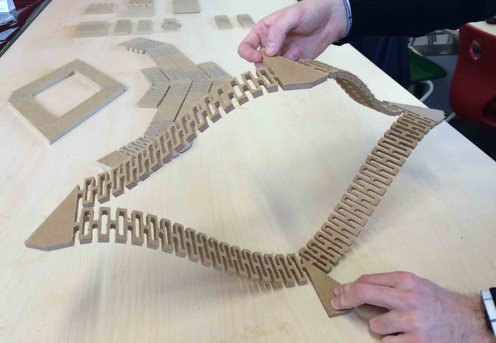
Déployé dome flattened. |
Déployé dome stretched. |
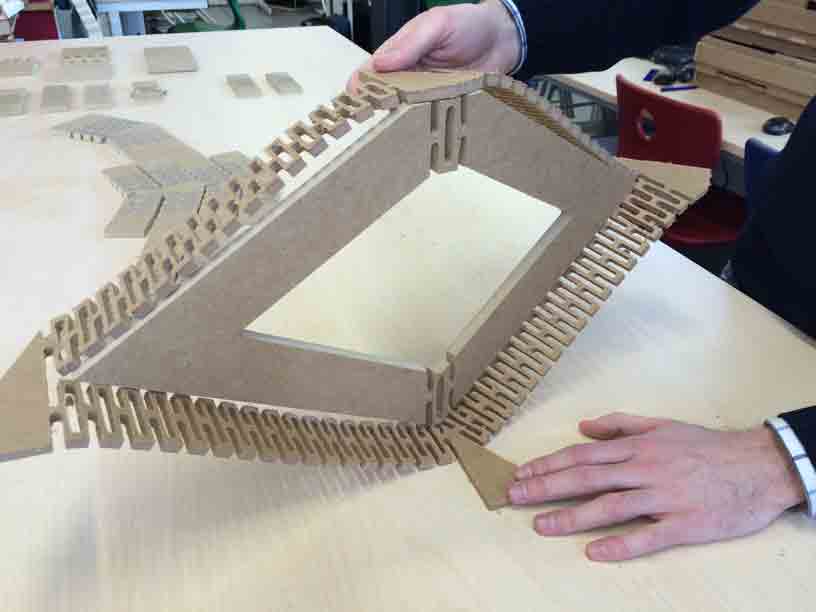
So I started with a sector of this déployé in order to test the elongation of one of its cells.
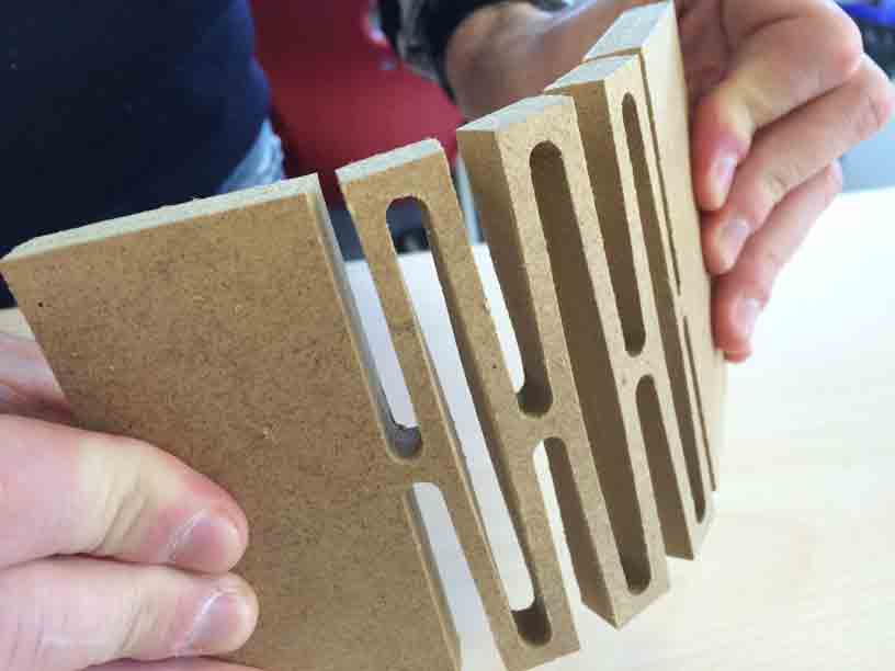
I began doing the flexure only in the place I want to became a hinge in the dome, but it breaks easily while lifting the cell up. So I found very interesting to convert the entire beam in flexures in order to flex soflty by extracting the half of the material what means an interesting a weight loosing.
|
 |
1 Designing pieces in AutoCAD. |
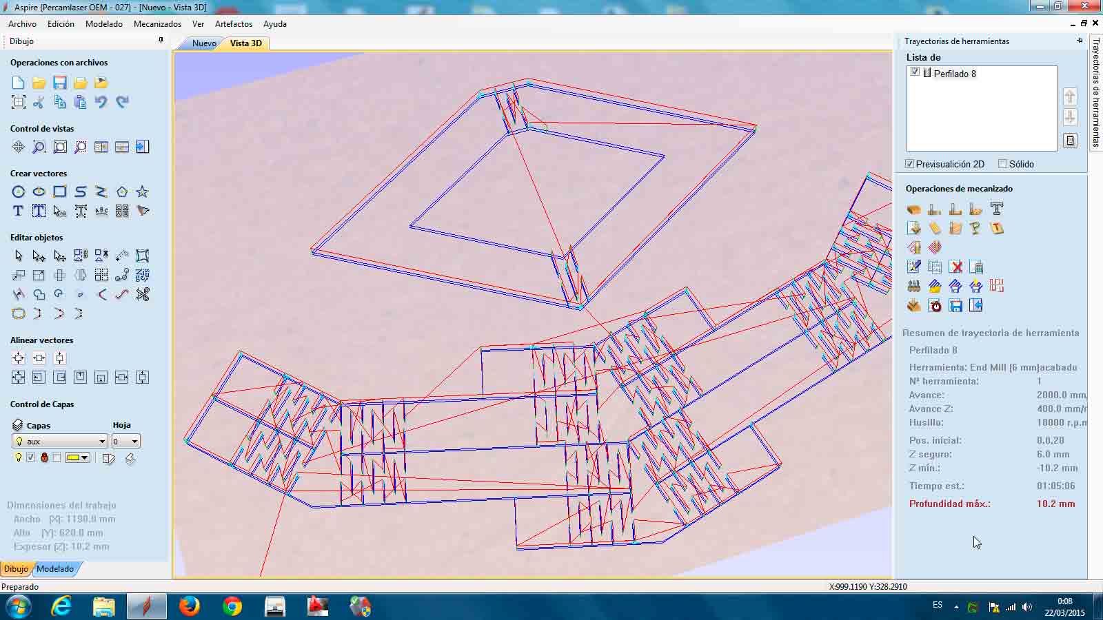
2 Converting vector file into code with Aspire. |
 |
 |
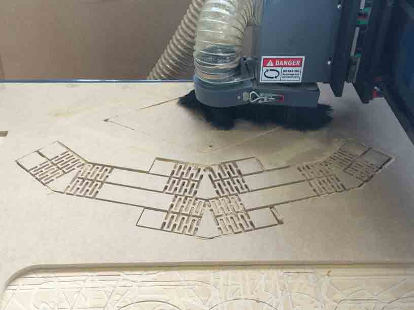
3 Milling CNC code with a Tec CAM 500. |
4 Testing the bending of the flexures. |
|
Selecting tool, feeds&speeds and material with Aspire. |
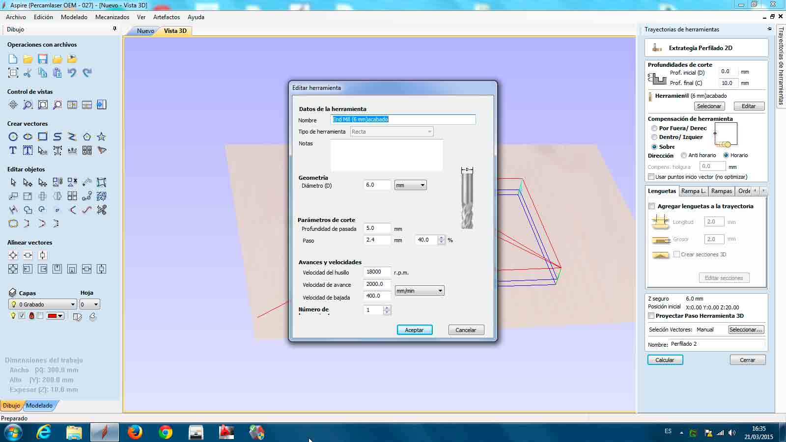
Tool: 6 mm of diameter
Speed: 18.000 rpm
Feed: 2.000 rpm
Material: 10 mm thickness MDF
Comparing the behaviour of the beam that only has flexure in the hinges against the beam which its entire beam is a flexure I found a soft response to the change of the bending direction in the second one, besides of its lightness.
|
|
Stretched and flattened flexure déployé. |
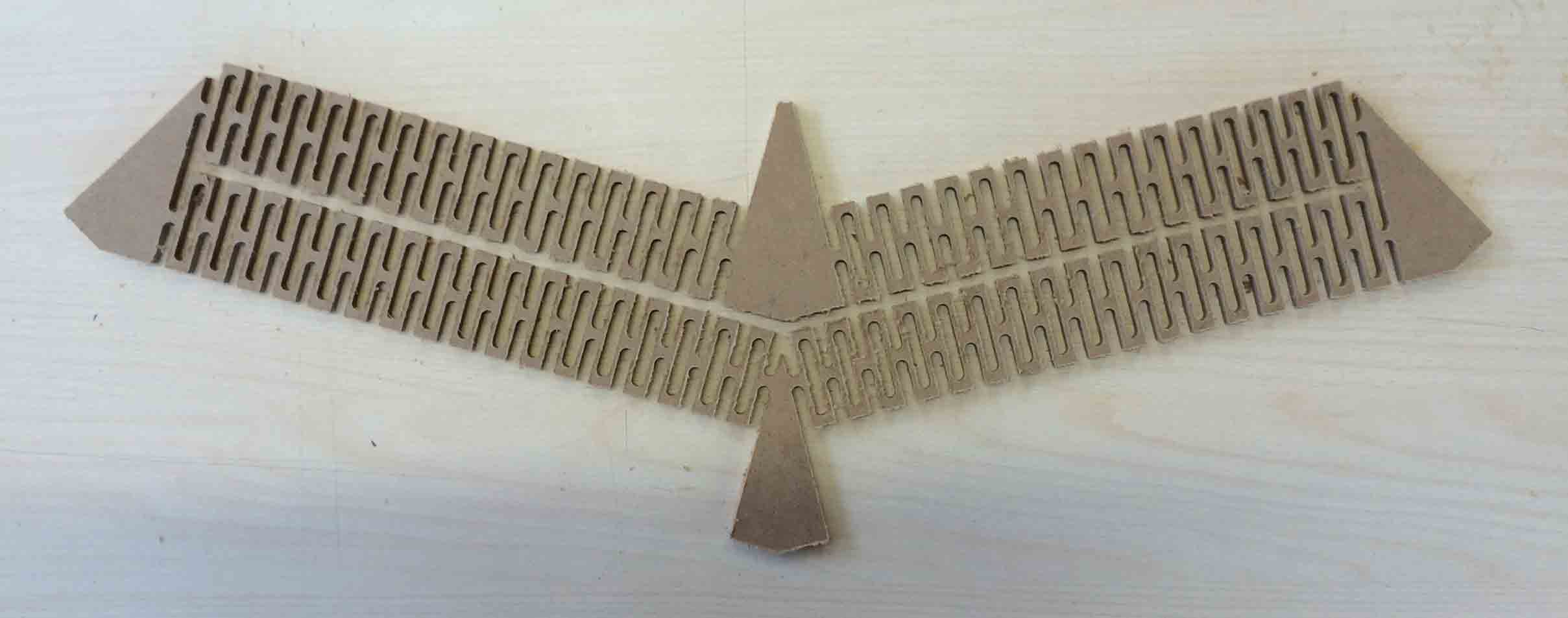
Here is my invention Déplofléx!