 FABRICIO SANTOS
Week 7 - Embedded Programming
Learn to program AVR microcontrollers. Read a microcontroller data sheet. Program your board to do something, with as many different programming languages and programming environments as possible.
Program an Arduino board // Program our board with Arduino IDE // Program our board with GCC
Program an Arduino board
By default Arduino has its own programmed routines and a LED and a Buttom to play them:
|
|
Blink program in Arduino. |
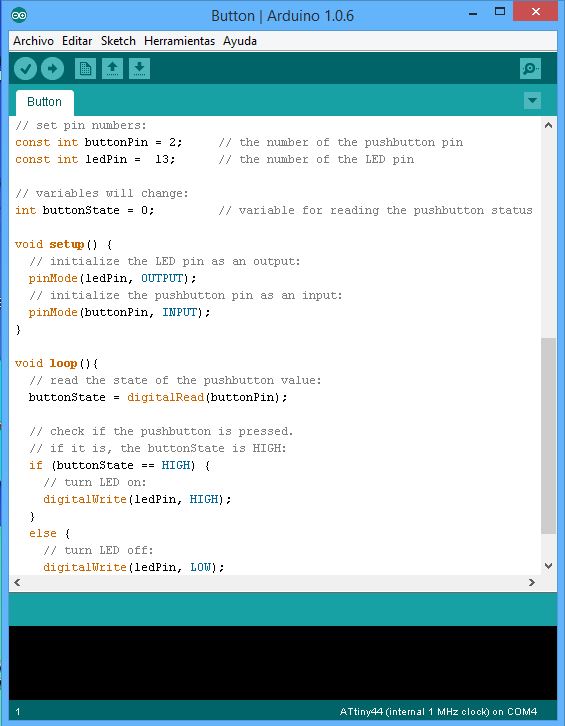
Buttom program in Arduino. |
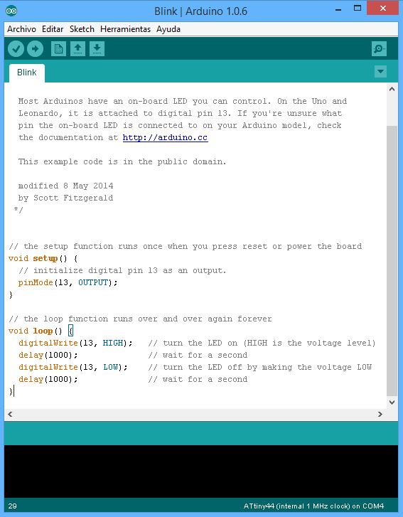
· Archivos\Ejemplos\01.Basics\Blink > when you load this routine the LED turns on and off for a 1 second in an eternal loop.
· Archivos\Ejemplos\02.Digital\Buttom > when you load this routine the LED is on and when yoy push the buttom it turns off while pressing.
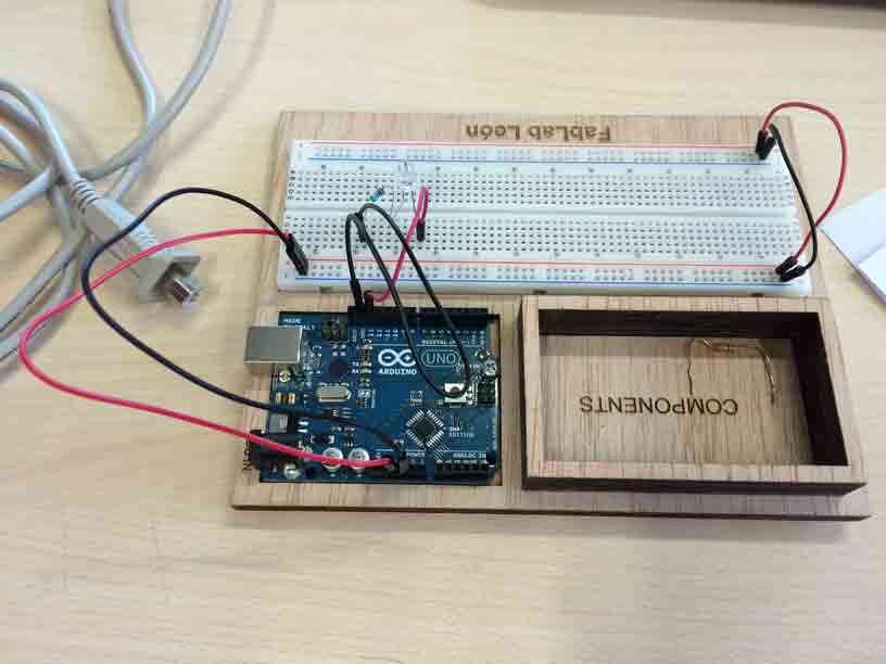
In order to understand how a protoboard works we use one where conect an external LED with its resistor against the Arduino board pins but changing the place to modify the Blink program in Arduino IDE and charge it to the Arduino microcontroller.
|
Playing an external LED in a protoboard conected with Arduino pins board. |
Program our board with Arduino IDE
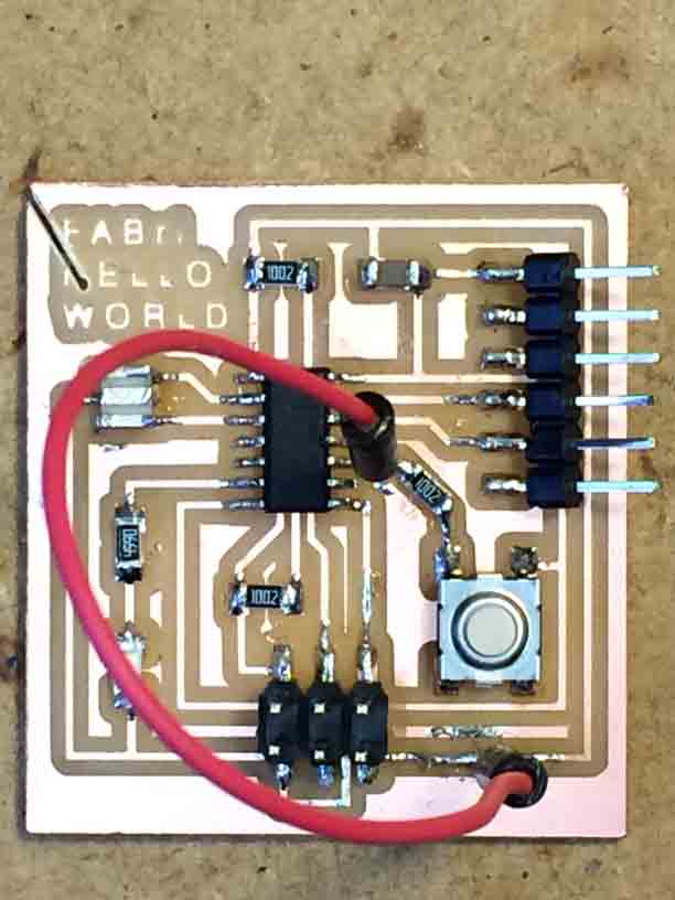
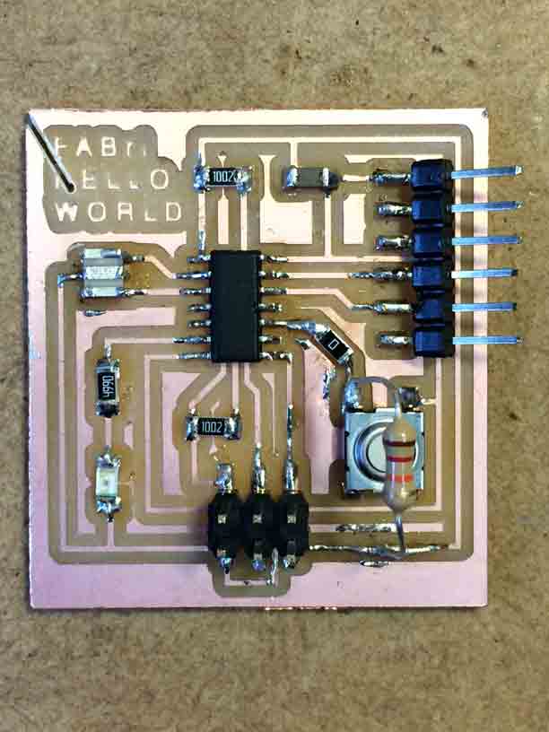
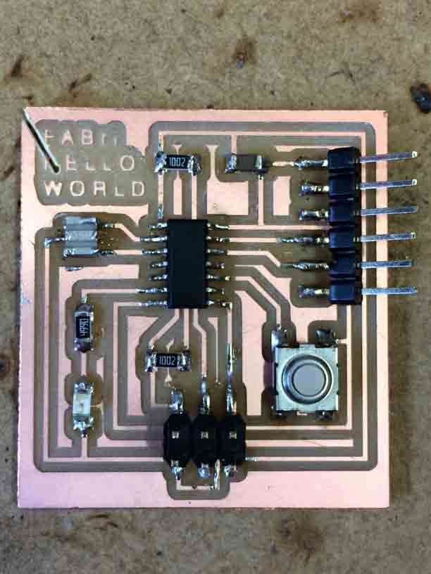
We are going to use Arduino (my version is 1.0.6) to program the components (LED and Buttom) of our Hello World board trough our FabISP.
· LED is an OUTPUT
· Buttom is an INPUT
Arduino is preset to work with its own cards so to use the FabISP microcontroller we need to download the ATtiny librery and create a hardware folder where paste it in this route > C:\Users\Fabrizio\Documents\Arduino\hardware\attiny
Then open Arduino and change selections in :
· Herramientas\Tarjetas > ATtiny44 (external 20MHz clock)
· Herramientas\Programador > USBtinyISP
Then we should change the number of the pins in the programming sheet because Arduino has 28 pins and ATtiny has 14.
So we use a conversion table ATtiny44 / Arduino for this:
| ATtiny 44A Pin Number |
Corresponding Arduino Pin Number |
Details |
| 1 | No number, no access? | VCC (+) |
| 2 | Pin 10 | |
| 3 | Pin 9 | |
| 4 | No number, no access? | Reset |
| 5 | Pin 8 | PWM |
| 6 | Pin 7 | PWM, Analog Input 7 |
| 7 | Pin 6 | MOSI, PWM, Analog Input 6 |
| 8 | Pin 5 | Analog Input 5, PWM, MISO |
| 9 | Pin 4 | Analog Input 4, SCK |
| 10 | Pin 3 | Analog Input 3 |
| 11 | Pin 2 | Analog Input 2 |
| 12 | Pin 1 | Analog Input 1 |
| 13 | Pin 0 | Analog Input 0, AREF |
| 14 | No number, no access? | GND (-) |
Following our Hello World board schema we need to change the pin number in the Blink program before charge it to the board. So we change pin 6 by pin 7 and the Blink program works:
/*
Blink
Turns on an LED on for one second, then off for one second, repeatedly.
Most Arduinos have an on-board LED you can control. On the Uno and
Leonardo, it is attached to digital pin 13. If you're unsure what
pin the on-board LED is connected to on your Arduino model, check
the documentation at http://arduino.cc
This example code is in the public domain.
modified 8 May 2014
by Scott Fitzgerald
*/
int LED = 7 ;
// the setup function runs once when you press reset or power the board
void setup() {
// initialize digital pin 13 as an output.
pinMode(LED, OUTPUT);
}
// the loop function runs over and over again forever
void loop() {
digitalWrite(LED, HIGH); // turn the LED on (HIGH is the voltage level)
delay(1000); // wait for a second
digitalWrite(LED, LOW); // turn the LED off by making the voltage LOW
delay(1000); // wait for a second
}
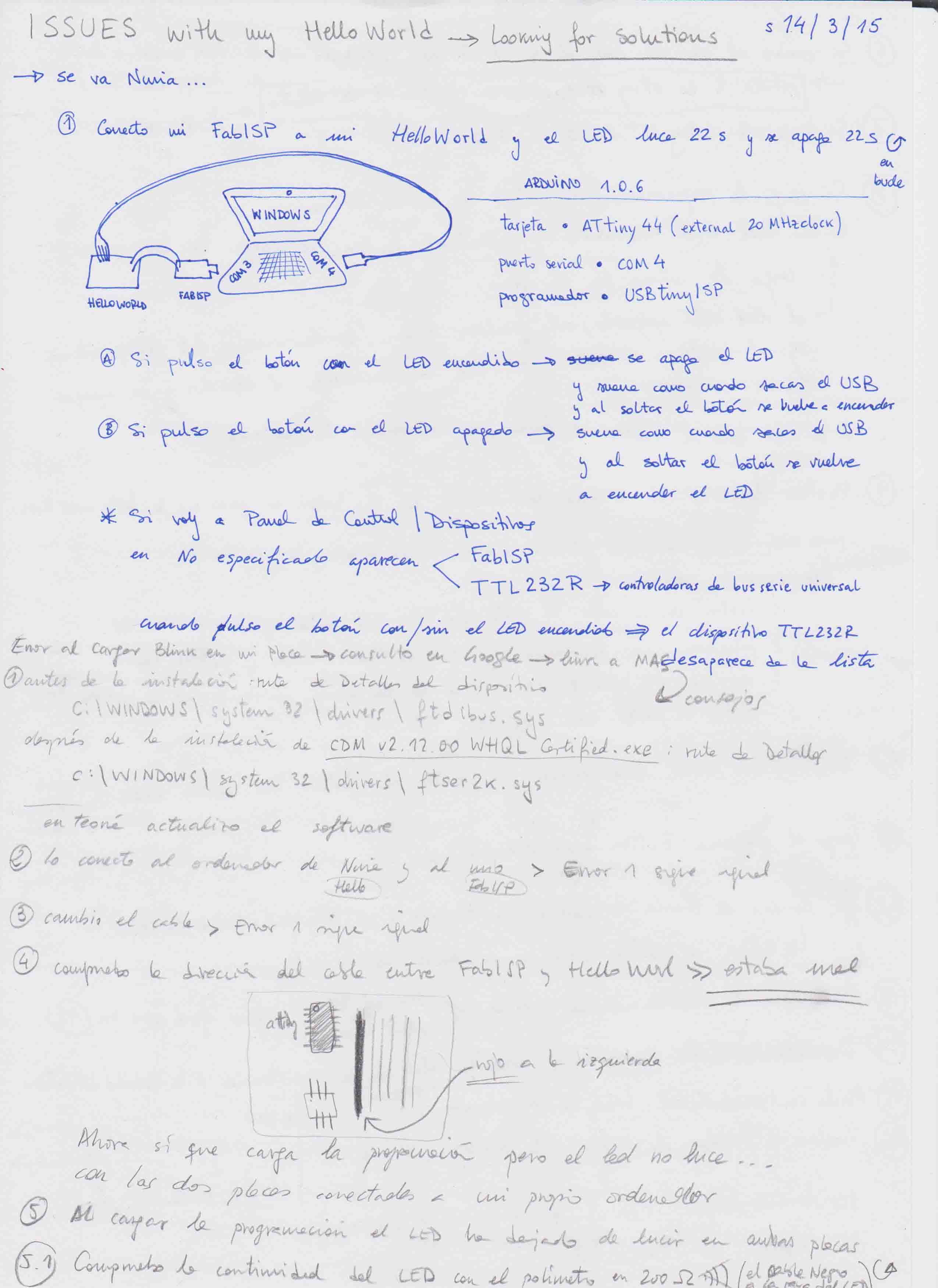
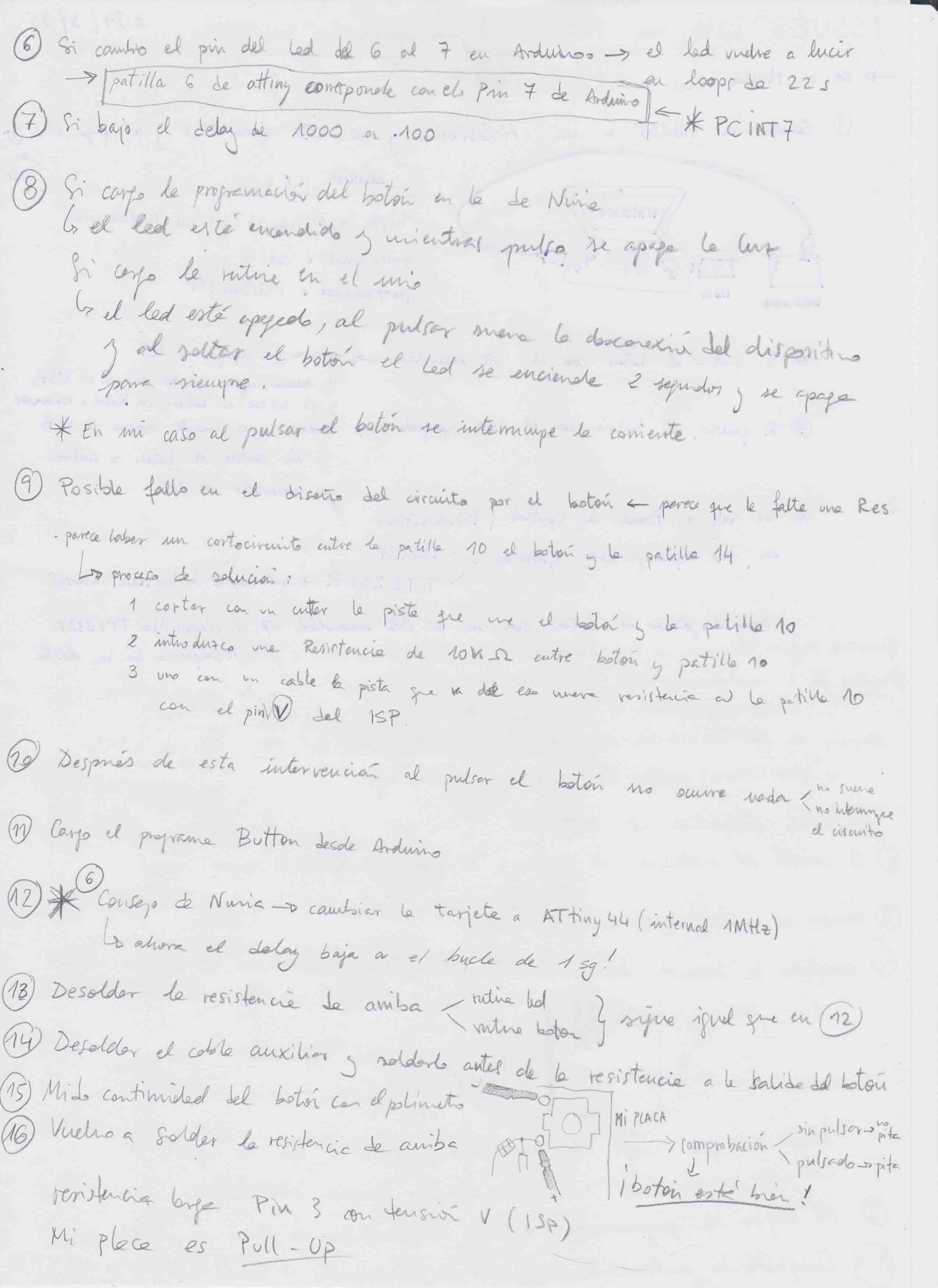
But when charging Buttom program problems started... So I try lots of solutions explaining them in my notes:
|
|
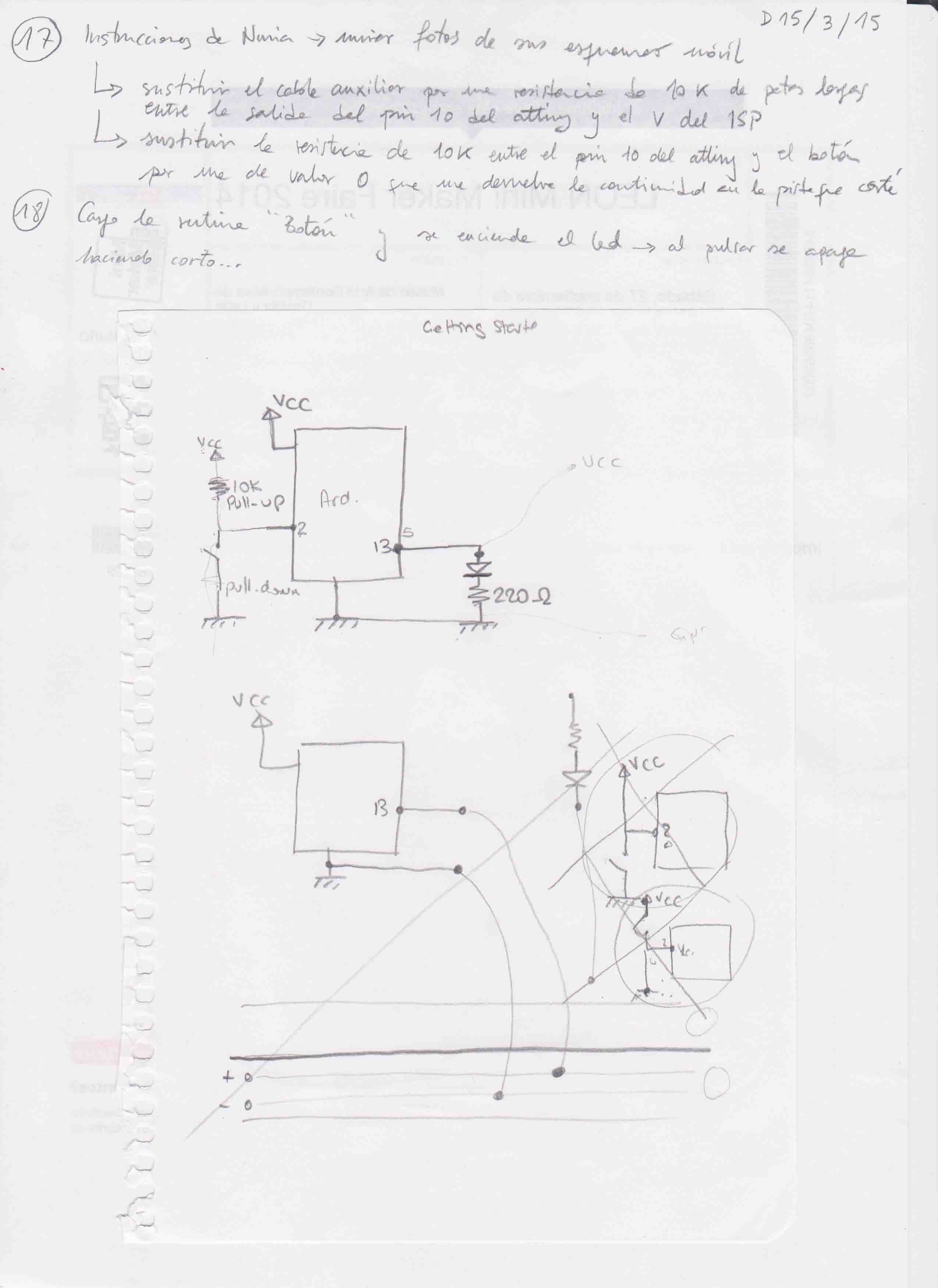 |
| Looking for solutions to run Button program on my Hello World board. |
|
 |
 |
|
Trying solutions... |
I have a lot of homeworks trying to fix the problem with the buttom of my Hello World board, but finally I got it because it was a soldering problem.
So I charged the Button example program of Arduino IDE making slight modifications of the pins in the code:
/*
Button
Turns on and off a light emitting diode(LED) connected to digital
pin 13, when pressing a pushbutton attached to pin 2.
The circuit:
* LED attached from pin 13 to ground
* pushbutton attached to pin 2 from +5V
* 10K resistor attached to pin 2 from ground
* Note: on most Arduinos there is already an LED on the board
attached to pin 13.
created 2005
by DojoDave <http://www.0j0.org>
modified 30 Aug 2011
by Tom Igoe
This example code is in the public domain.
http://www.arduino.cc/en/Tutorial/Button
*/
// constants won't change. They're used here to
// set pin numbers:
const int buttonPin = 3; // the number of the pushbutton pin
const int ledPin = 7; // the number of the LED pin
// variables will change:
int buttonState = 0; // variable for reading the pushbutton status
void setup() {
// initialize the LED pin as an output:
pinMode(ledPin, OUTPUT);
// initialize the pushbutton pin as an input:
pinMode(buttonPin, INPUT);
}
void loop(){
// read the state of the pushbutton value:
buttonState = digitalRead(buttonPin);
// check if the pushbutton is pressed.
// if it is, the buttonState is HIGH:
if (buttonState == HIGH) {
// turn LED on:
digitalWrite(ledPin, HIGH);
}
else {
// turn LED off:
digitalWrite(ledPin, LOW);
}
}