 FABRICIO SANTOS
Week 6 - Electronic Design
Learn to modify one of our existing electronics "hello world" examples or create your own project. Add at least a buttom and a LED with current-limiting resistor.
Design circuit >> Mill board >> Solder components >> Check board
|
 |
 |
 |
Designing the electronic circuit with Eagle.
|
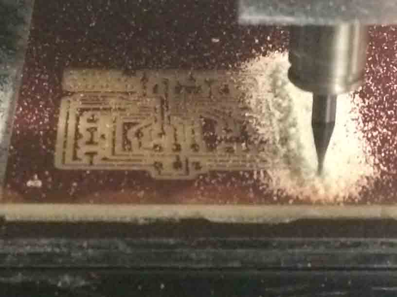
Milling the copper board.
|
Soldering components to the board.
|
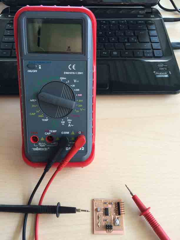
Checking board conections.
|
Design Circuit
I chose Eagle to design electronic circuits helped by my classmate Raúl Diosdado at Fab Lab León.
|
 |
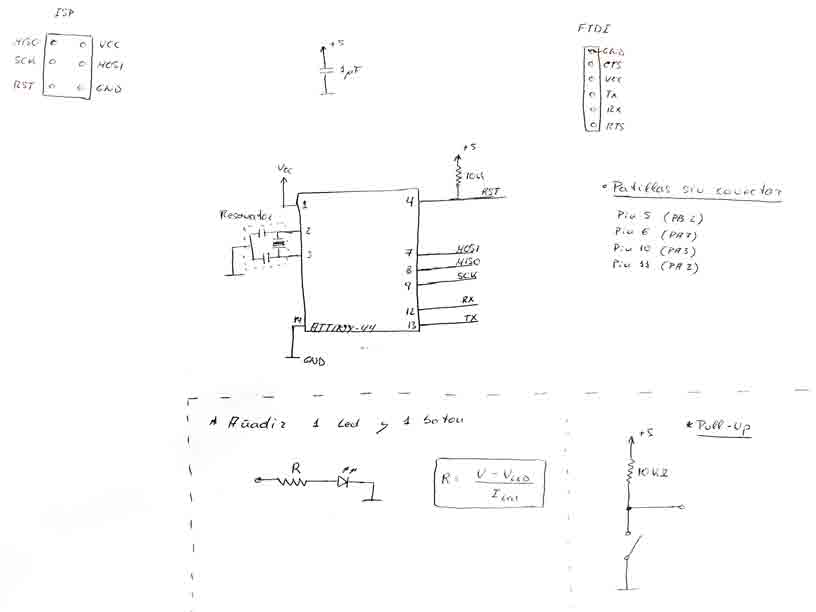
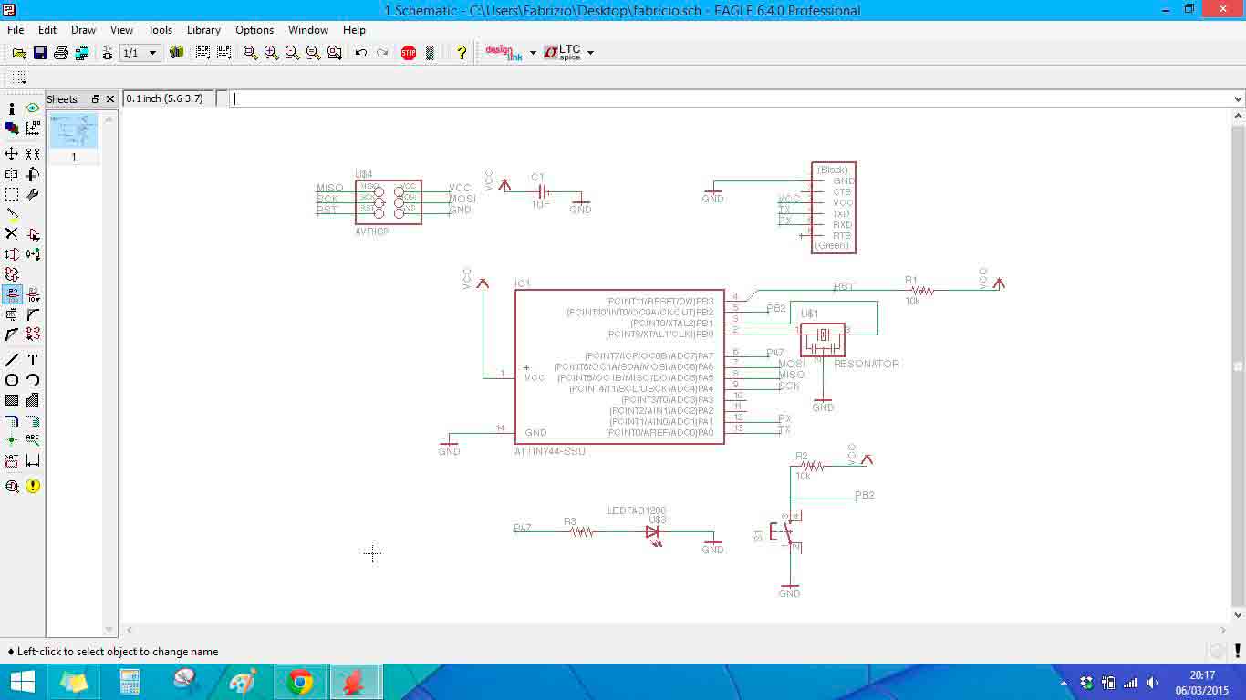
Electronic schema by my classmate Raúl Diosdado.
|
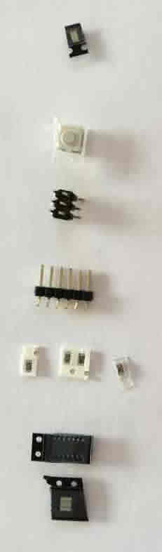
Components.
|
First of all we copy the electronics library from the Academy in our lbr program folder in order to choose inventoried components.
|
FAB library inventored components.
|
We took as a reference the echo hello-world board and we added a LED and a buttom.
|
Neil´s design Hello World board.
|
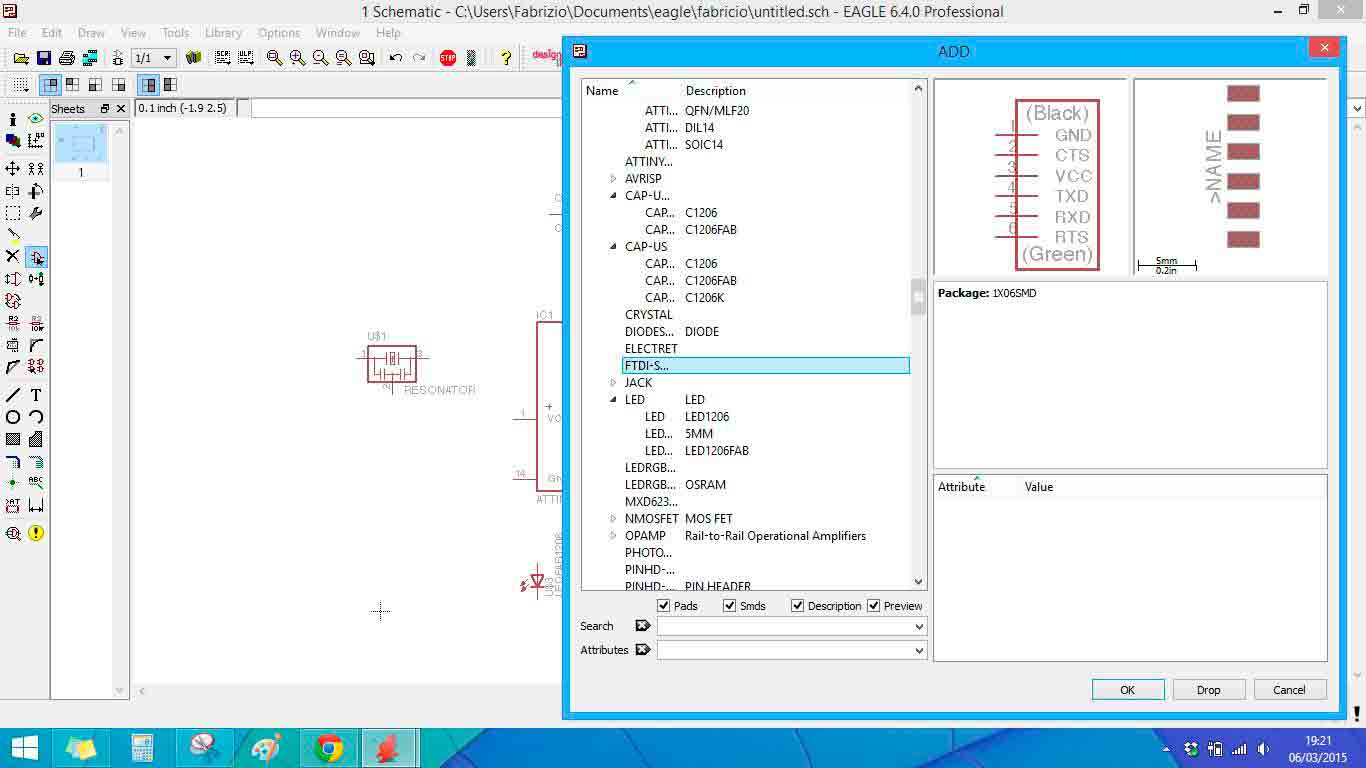
Then we open Eagle:
· File / New Project / (right buttom) New Schematic
· ADD > search for fab library and ensured that every selected component has the 1206 encaptulated.
- resonator 20 MHz > 2 is the GND (ground) and fix the direction shuld be down
- capacitator > 1µF
- resistors > 100K
- ATTINY 44-SSU > the circle marks the orientation and VCC should be top left
- AVR ISP > 2X03
- FTDI-S > 1X06SMD
- LED (+ resistor) > the end marked with a green line is the negative pole, which must be conected to ground
- buttom > 6mm_SWITCH OMRON SWITCH
· To search some specific component > introduce the name fallow by * and push search
· Start conecting components by wires
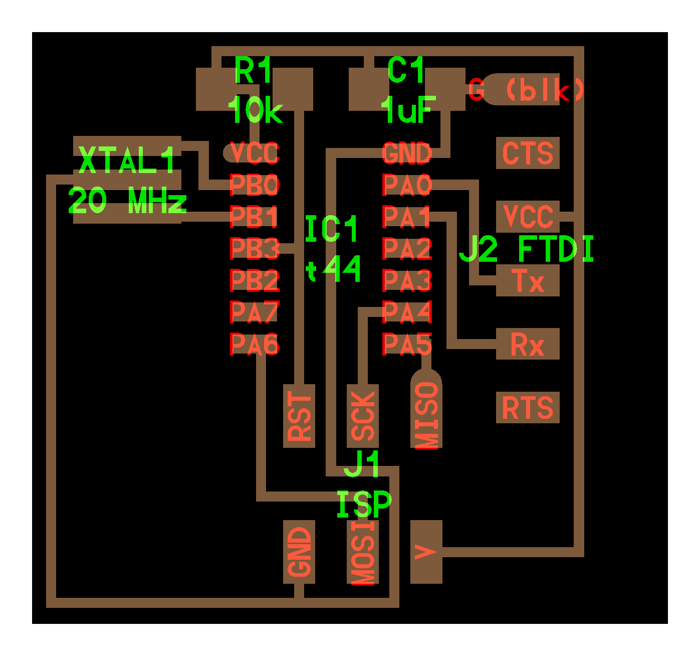
Schematic view in Eagle.
· Stick labels in the end of the cables of the ATTINY44 to reference conections between components before moving to the board mode.
- stick labels in pins 4,7,8,9,12,13
- pins 5,6,10,11 would be free for LED and buttom
- CTS and RTS should not be conected
· Move from Schematic to Board mode > File / Switch to board
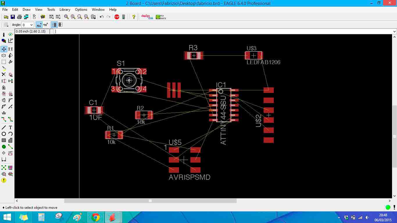
· Every stuck labbels become conections between components shown in thin yellow wires.
Switch Schematic to Board view in Eagle.
· Select the wire to change the thickness of the future milling circuit tracks > File / Design rules...
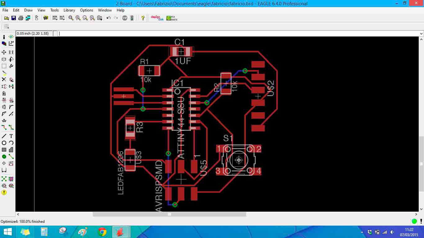
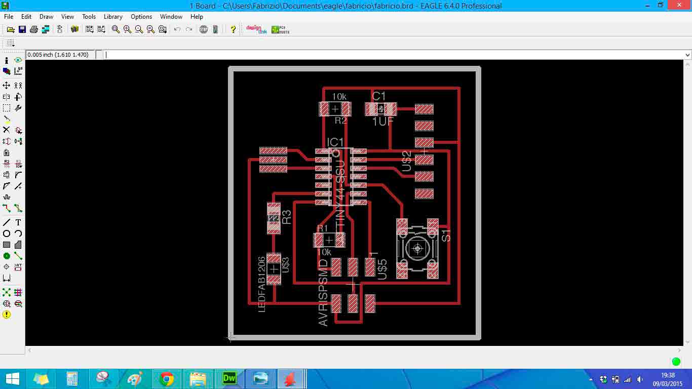
Routering the components of the board in Eagle.
· Show (eye icon) > first click show and then clicking a red pin of a component it shows you wich components should be conected.
· Info (i icon) > shows properties of each component while clicking on it.
· Adjust board boundary to the traces design and change the thickness of edge > Info / Properties / Width 32 (milling tool thickness).
· All the project is saved in Documents / Eagle / "Fabricio"
· Desig with care to avoid unnecessary crossings (bridges with 0 value resistances) > For that I decided to place the LED whith its resistor in the left side of the ATTINY44 in the PA7 pin and the button in the left side with its resistor too.
|
Preparing the boart to export it from Eagle to .png.
|
· When the design is finished > File / Export / Image (1200 dpi / monochrome / .png)
· deselect all the layers
· tracks are in TOP layer
· boundary are in DIMENSIONS layer
Preparing the boart to export it from Eagle to .png.
Inverting the boundary color to black in order to be milled.

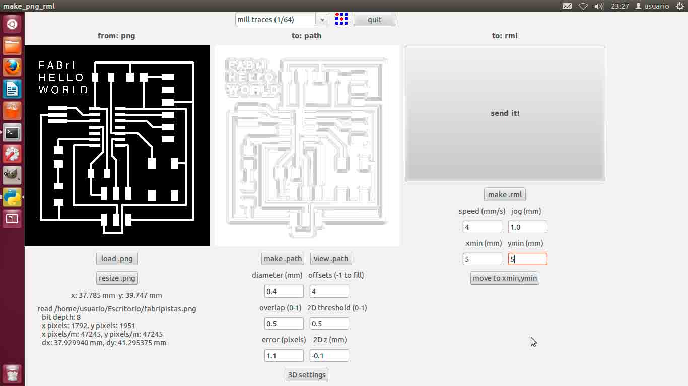
Then mill the board, solder it and check every conection with the multimeter.
|
Seending the .png board file from Fab Modules to Roland Modela to mill it. |
|
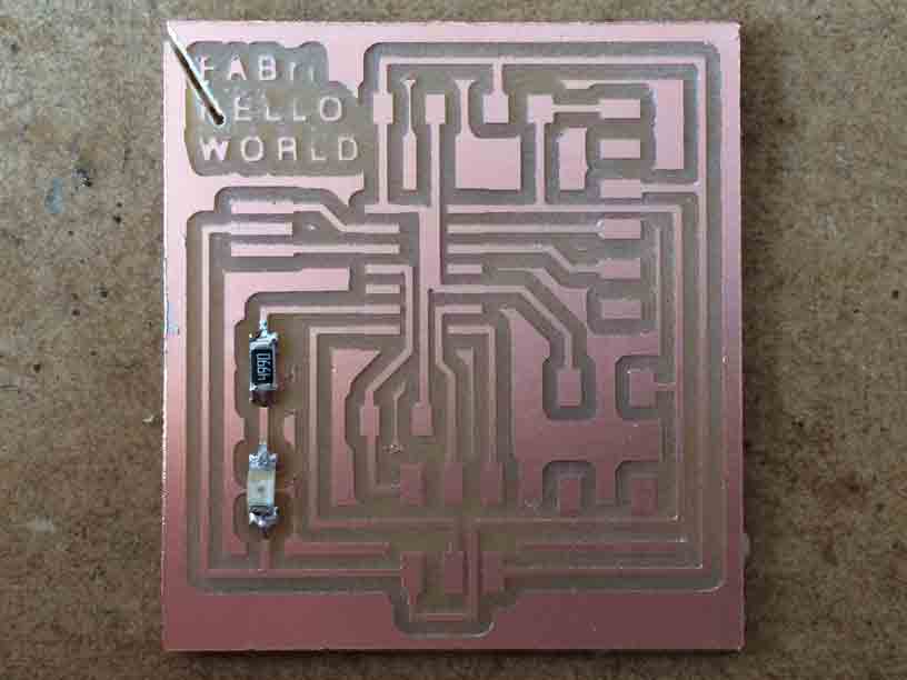
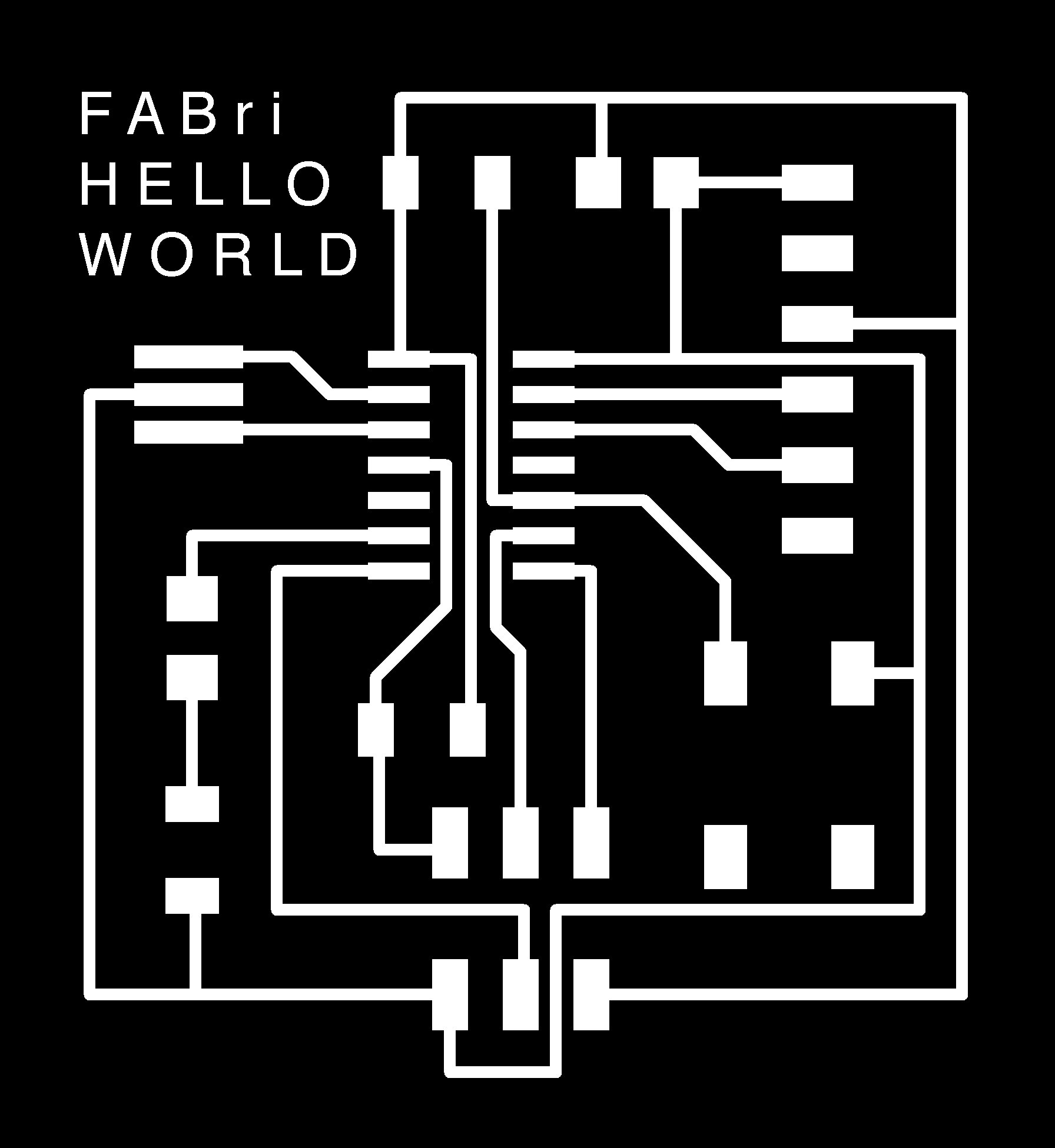
FABri HELLO WORLD board. |
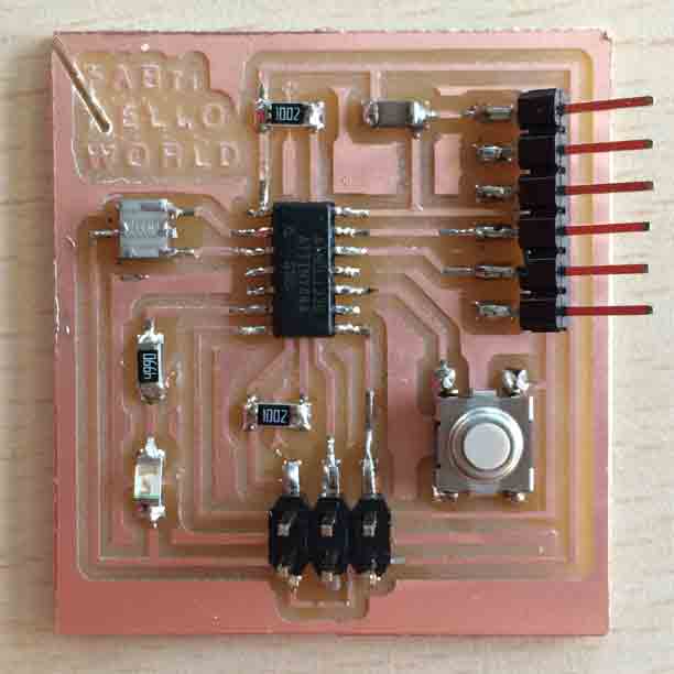
My FABri HELLO WORLD is ready to be programmed!
- - -
Files:
· FABri HELLO WORLD (Eagle schematic)
· FABri HELLO WORLD (Eagle board)
· FABri HELLO WORLD (png traces)
· FABri HELLO WORLD (png boundary)