Week 6
Electronics Design

Redraw, add, check and make the board
The assignment for this week is to produce the Hello World board, adding at least a button and an LED to the original design, using some of the proposed software. Furthermore we should investigate the tools needed to simulate electronic designs.
Re-design board
I use Eagle freeware version to redesign the hello board. To work with Fab inventory components it is necessary to download the eagle libraries from Fab Lab Providence' tutorial.
I started studying basic tutorials of Eagle following mainly the process as the video and reading the Data Sheet of each component that interested me.
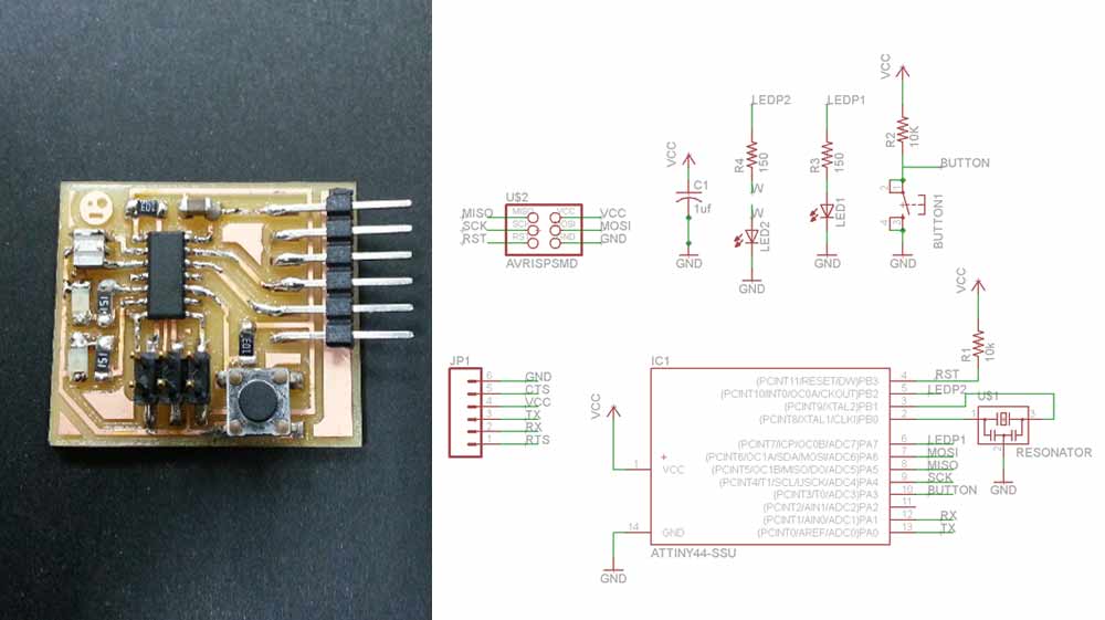
After loading the library in Eagle and opening the Hello World board I started to re-design the bord:
- I decided to put two LEDs 1206 (Osram Opto CHIPLED 1206 Series Red LED and Osram Opto CHIPLED 1206 Series Yellow LED) and a Button (Black Button Tactile Switch, SPST-NO 0.05 A@ 12 V dc 1.4mm). After reading the Data Sheet I calculated and chose the appropriate Resistors 1206 (I=V/R);
- I placed all the extra-components over the schematics and I assigned each net-structure to the pins of the microcontroller, to the GNR and to the VCC;
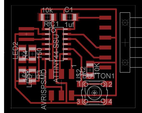
- Into the board panel I distributed all the components. Then I skip and create ease connections: I have studied the connections and the components to Hello board and I tried to follow the same order to add my custom components;
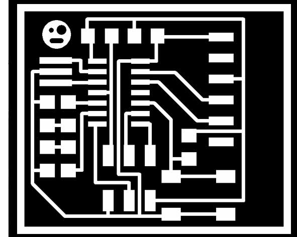
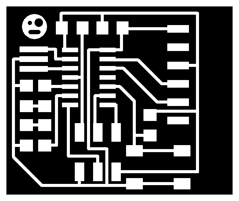
- To create the "traces.png" file I turned off all layers except for top layer into Eagle. After going to file> export> image and I chose 600 dpi resolution and I checked the button Monochrome;
- After created my .png traces file I opened it into Photoshop and I edited cutting the extra black parts on the borders and then I added change the canvas size expanding 20px for each side of the area;
- I Duplicated the same file and I selected the white border. Painted it black and then "select inverse" to painted the other area white.
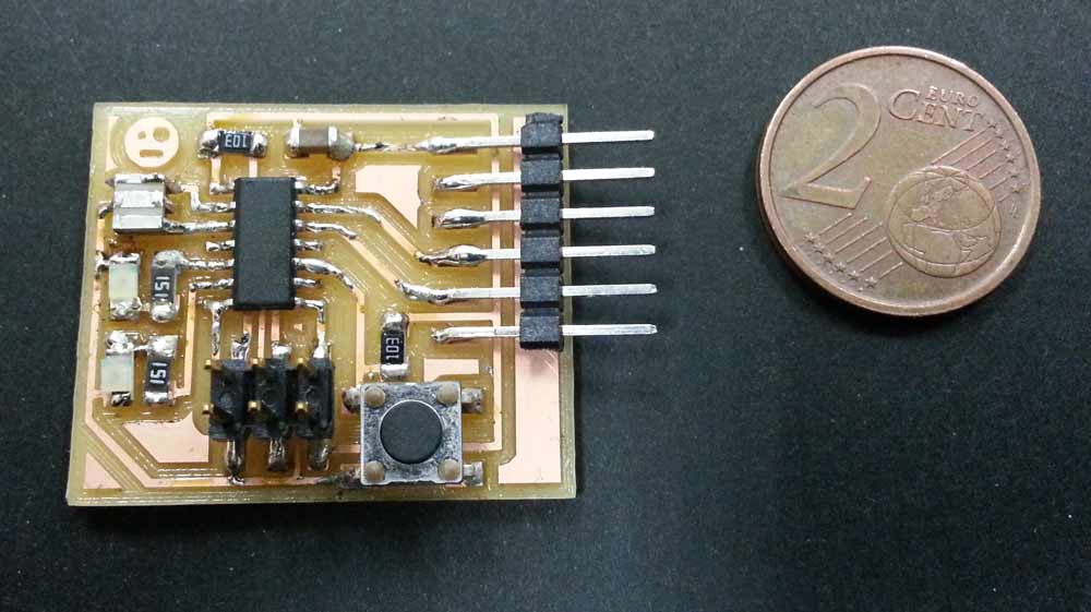
milling, soldering and testing
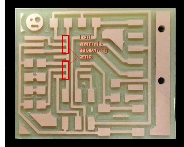
Using these files processed by Fab Modules and the same procedure utilized for FABISP, I milled the new borad with Roland SRM-20 ( I had a problem of size of the tracks using the fab modules, but I solved directly on the board cut manually the wrong parts and fixed the file increasing the distances) and then I soldered each components. Using a tester I checked the circuit and components, but not everything worked: I had to change the red LED because I burned it and re-soldered the 6 pin header.
Using Fritzing and 123D Circuits I tested and simulated the circuit before building it.
Download Files
Eagle:
- hello_marco.sch (hello_marco.rar)
- hello_marco.brd (hello_marco.rar)
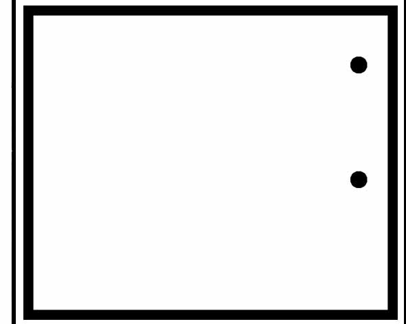
PNG:
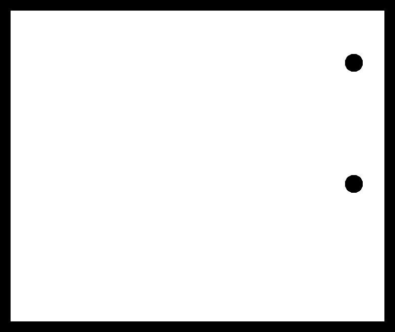
Programs: CS Eagle, 123D Circuits, Fritzing, Photoshop.
Machinery: Roland SRM-20.