Week 13
Networking and Communications
Assignment purpose
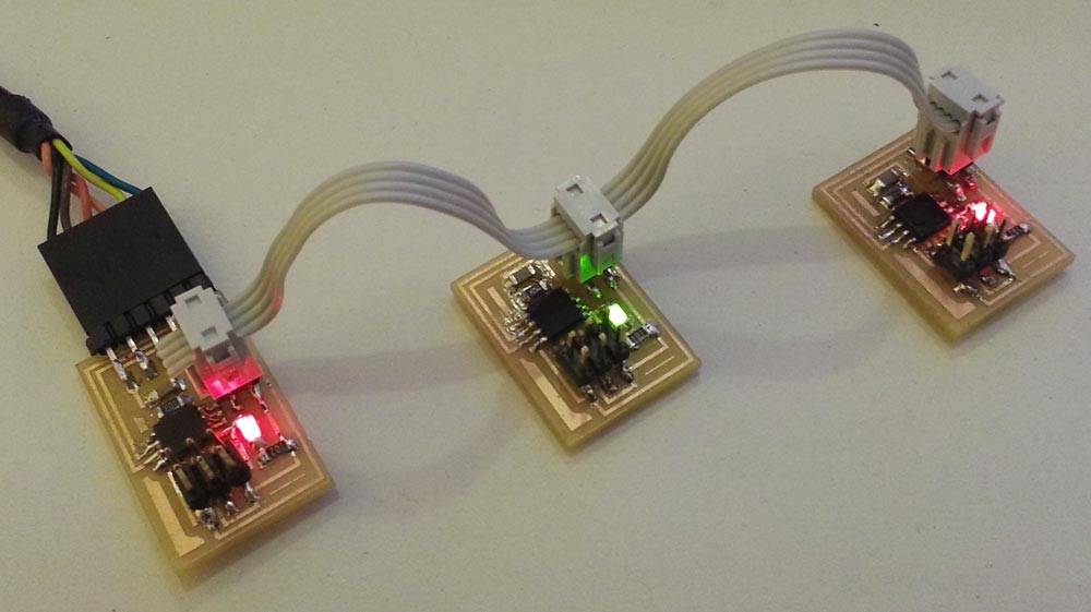
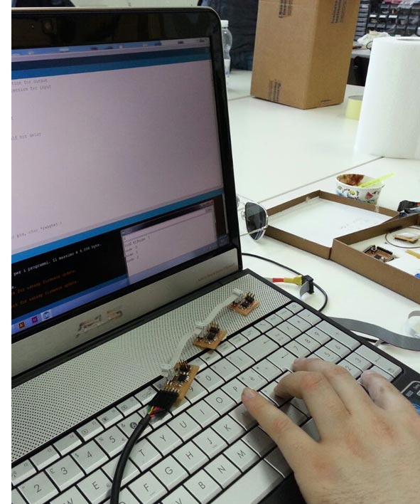
The purpose of this assignment was created networking between computer and boards using the example of serial bus. The bridge board was connected to a computer via a FTDI cable. The two node boards were connected to the bridge board using a connector.
For this example I used two node boards, but was possible to connect multiple nodes.
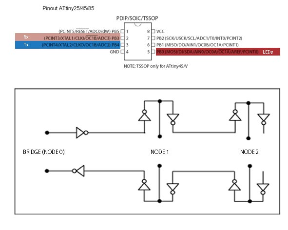
Bridge and Node Boards
I used 1 hello.bus.45.bridge and 2 hello.bus.45.node. Components for each board:
- 6 pin header
- 4 pin header
- FTDI header ( just for the Bridge Board to connect to computer)
- Resistor 10 K
- Resistor 1 K
- Capacitor 1 uf
- LEDs
C code and Programming
I downloaded and used the hello.bus.45.c code ( and makefile) proposed in the schedule of Fab Academy week. Each board was programmed individually, to do this I modified the C code for each board:
- Each node needs to have a different node ID number (0, 1, 2, 3, etc). The "bridge" board is also a "node".
- In the C code, I changed the line:#define node_id '0' and I saved the file.
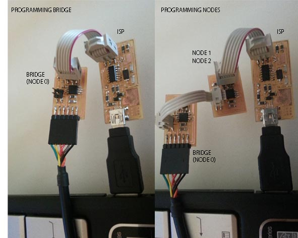
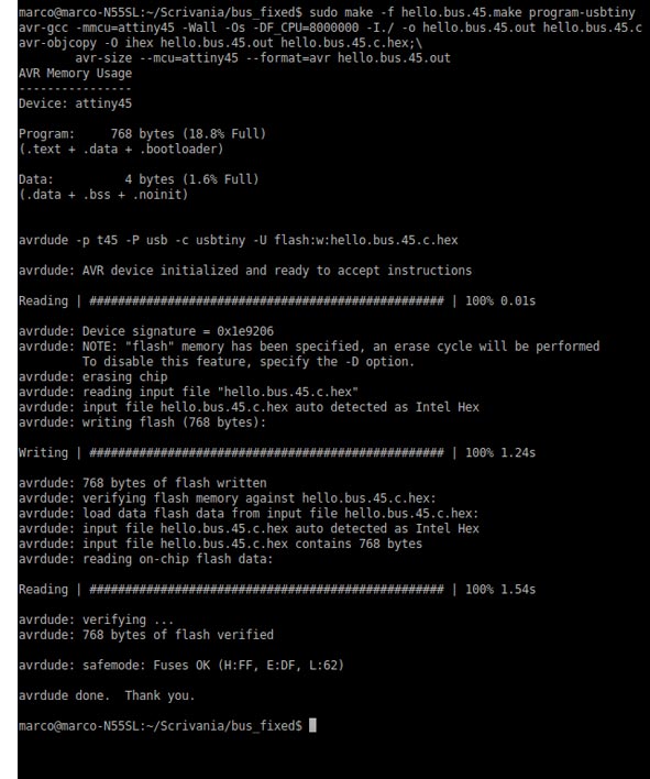
- I connected the bridge board to computer with the FTDI header and I programmed it using the FabISP, I flashed the bridge board as node 0: sudo make -f hello.bus.45.make program-usbtiny
- Next, I modified again the C code and changed the node ID to 1:#define node_id '1' and I saved the file.
- I used the bridge board to power node boards and connect them to TX and RX. Then I flashed the node board as node 1: sudo make -f hello.bus.45.make program-usbtiny
I Repeated this process for node 2.
INTERFACE: USING THE SERIAL MONITOR IN ARDUINO TO TALK TO NETWORK
After flashing boards whit 3 different node numbers:
- I Plugged the bridge Board into computer (FTDI cable);
- I Connected the nodes with 4 pin header (Tx,Rx,Vcc,Gnd);
- Open a Arduino IDE and the serial monitor;
- Make sure the baud rate is set to 9600;
- Enter number of a note (pick a number) into serial monitor - press the
- The LEDs on all the boards lighted up once;
- After all the boards lighted up, the board with the number entered into the serial monitor lighted up again;
- The node name (node 0, node1, node2) also was displayed on the serial monitor.
Problems and Solutions
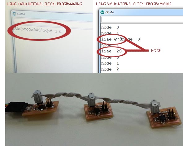
The first time I programmed the boards at low speed (I tried to 1 Mhz), but in the serial monitor I could not read anything. I increased the programming speed at 8 MHz and I fixed it.
To read better the lighted up of LEDs, I changed the delay in the C code from 100 ms to 1000 ms: #define led_delay() _delay_ms(1000) , I saved the file and re-programmed all the boards.
I had a lot problems with noise of node 2 . When I used the Arduino serial monitor the node name displayed was “strange” and each time different. I controlled the board and solder, I changed the connector and rolled the wires to reduce the interference, but I just reduced the noise. I could not fixed completely this problem.
Download Files
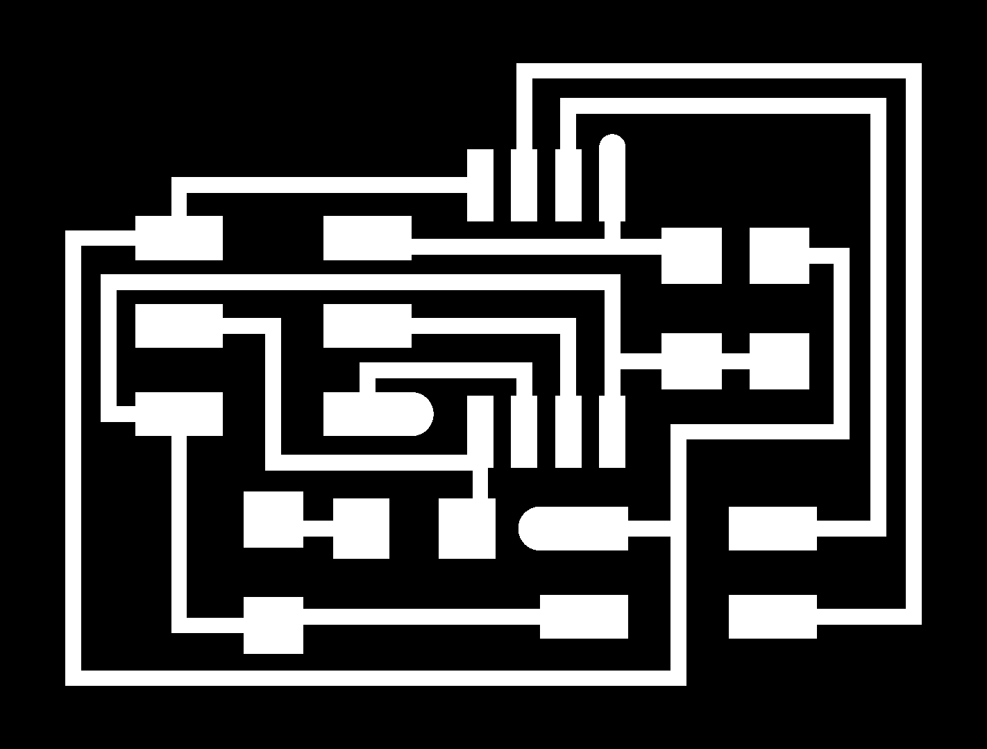
PNG:
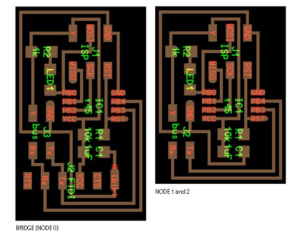
- hello.bus.45.bridge_traces.png
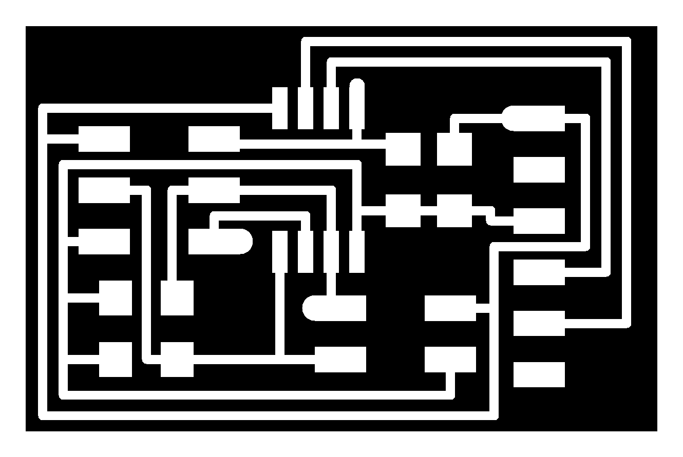
- hello.bus.45.bridge_interior.png
- hello.bus.45.node_traces.png
- hello.bus.45.node_interior.png
C code and makefile:
Programs: Eagle, Photoshop, IDE Arduino.
Machinery: Roland SRM-20.