Week 10
Input Devices


Input Devices
Measure something: add a sensor to a microcontroller board that you've designed and read it
Arduino Board Design
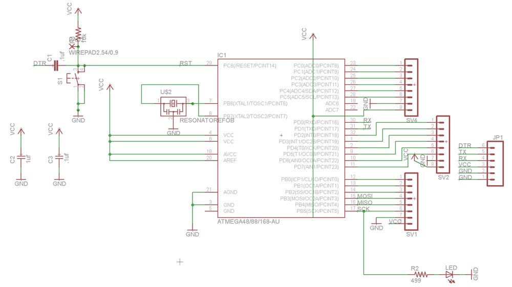
For this exercise I decided to make an Arduino from scratch and then work in some breakout boards to make the inputs and outputs.
Based on Fabkit 0.4
Components:
- FTDI Communication
- 2 Unpolarized Capacitors 1206 0.1 uf
- Unpolarized Capacitor 1206 1 uf
- Electrolytic capacitor 10 uf
To write the bootloader I used the IDE from Arduino. It's necessary choose on Tools > Board > Arduino Pro or Pro mini (3.3V, 8) before and press the Reset Button when you are making the booloader
Input device
The aim of this class assignment was to create a microcontroller with an input device.
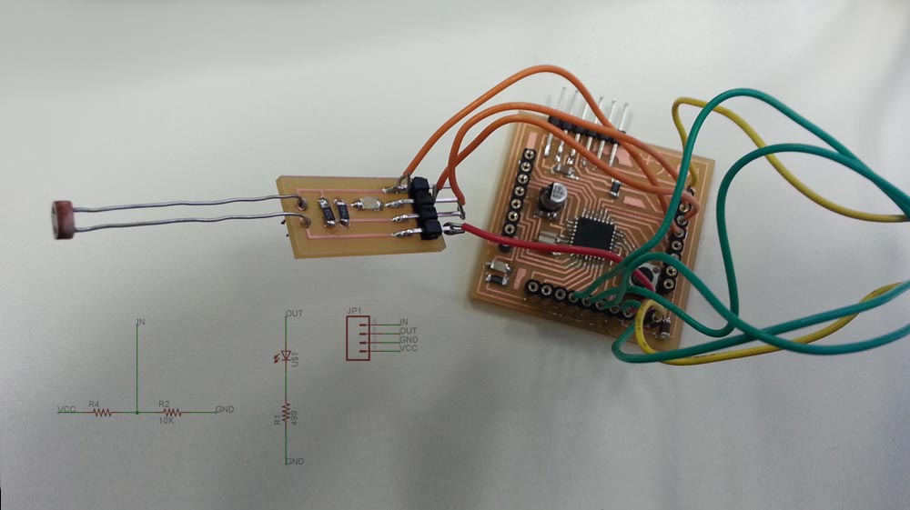
I am including this assignment for my final project. Initially I designed a shield with a limit switch, but that was really similar at button switch used 3 week ago. For this reason I created a microswitch using a photoresistor to try another sensor. I want to try infrared led and ultrasonic sensor soon.
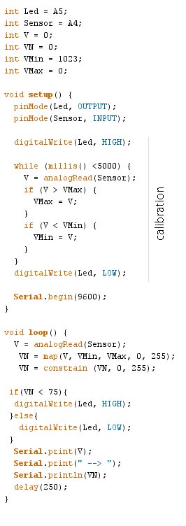
I used the sensor as a resistor and I located a resistor 10k after the input trace to read the changing values. I used the led just for an immediate output and to calibrate the range of the sensor.
A photoresistor is a light-controlled variable resistor. The resistance of a photoresistor decreases with increasing incident light intensity. the electric current flowing through this component is proportional to the intensity of a light source. A photoresistor can be applied in light-sensitive detector circuits, and light- and dark-activated switching circuits.
Components:
- Photoresistor
- Header 4 pin
Programming
IDE Arduino Sketch to program the microcontroller:

Download Files
Eagle:
- fabkit_modif.sch (fabkit_modif.rar)
- fabkit_modif.brd (fabkit_modif.rar)
PNG:
Arduino IDE:
Programs: Eagle, Photoshop, IDE Arduino.
Machinery: Roland SRM-20.
