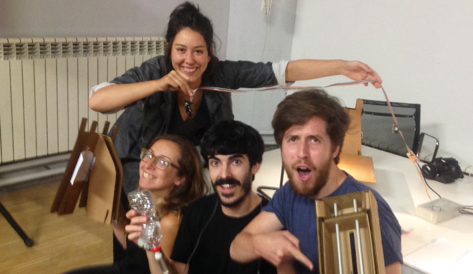
MACHINE CONCEPT
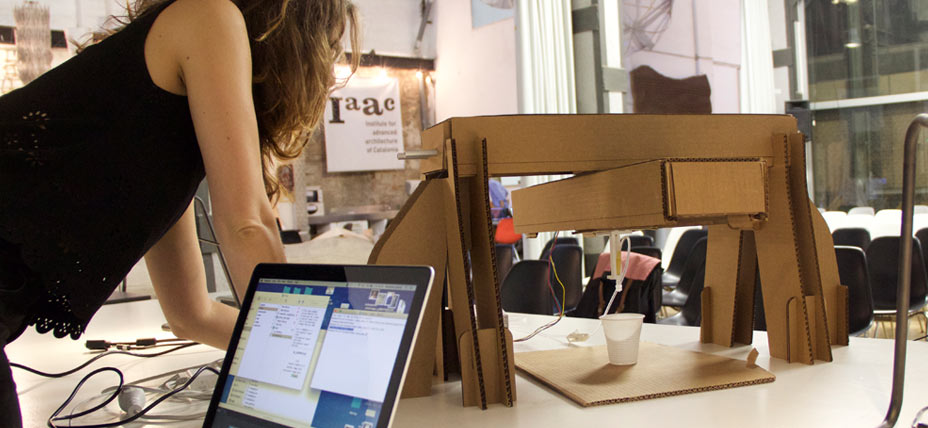
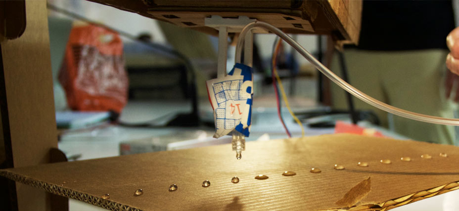
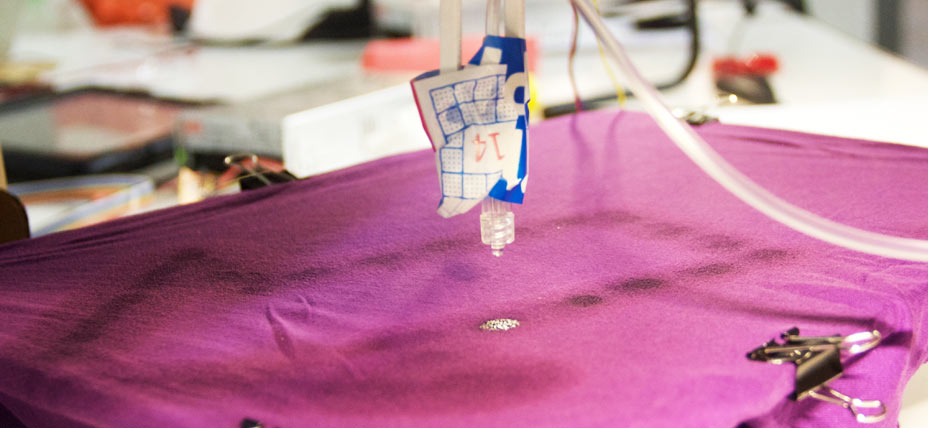
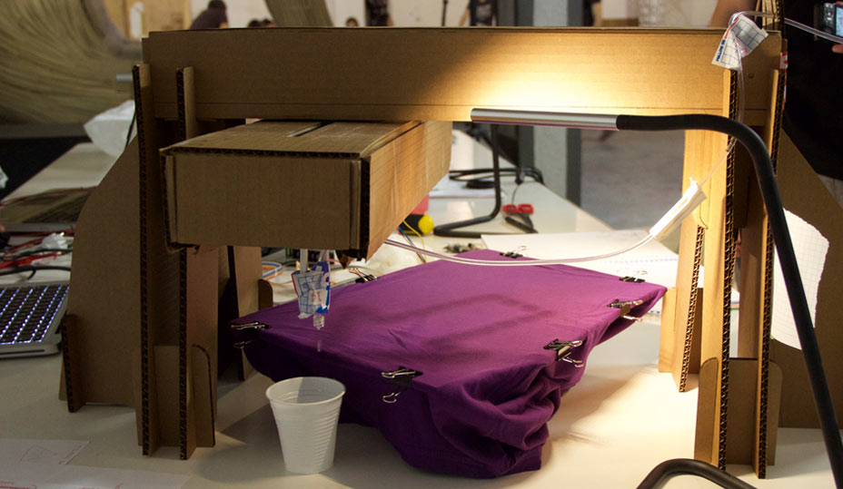
For the machine design/building weeks our group decided to develop a machine capable of 'drawing' by dropping water on surfaces.
The inspiration came from our fascination with the Turkish marbling technique, which involves dropping coloured pigments in a water tank. The paint drops spread on the surface of the water and when a material (textile or paper) is applied on the surface of the water, the paint adheres to it, creating a beautiful marbling effect.

In the span of this project we didn't get as far as testing this technique, we focused instead on getting the dripping system to work as an authomatised process.
Nevertheless we realised that by creating a machine with these characteristics, in the future we could actually explore a variety of other creative possibilities, which would be greatly expanded by the range of materials we could apply.
HARDWARE OVERVIEW
In terms of physical structure of the machine these were the tasks to complete:
- producing the 2 carboard stage
- fixing the 2 cardboard stages together
- designing 'legs' for the stages that would hold one steady and leave the other free
- design the dripping system
Théo was mainly in charge of the hardware system, with few contributions from the rest of the team.
In terms of the dripping system, many options were investigated.
We looked at peristaltic pumps, an electronic valves, gardening micro-dripping systems.
Dani 3D printed the parts necessary to attach a peristaltic pump to a nema 17 motor and got the pipes that would control this part of the system.
Refining the project development ideas few challenges were pointed out by the team regarding the dripping system: observing the peristaltic pump we realised that the water quantities flowing through the system at each stepper motor step would have given us a stream of water rather than a single drop.
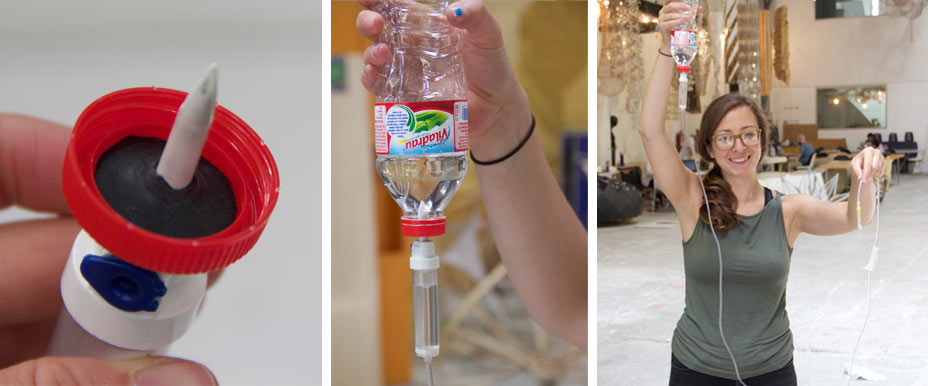
We then looked into other options and we considered that the best option would be a medical tube for intravenous drip, since it allows controlled release of fluids drip by drip. The interval between drips can also be controlled easily through a manual little valve, which comes in very handy.
- Théo took charge of getting the tube and designing a tube holder that would attach to the free stage and work as a 3d printer header allowing the water dispenser to move on the canvas.
- I helped in finding a solution for connecting the tube holder to a plastic bottle (used as container).
CODE OVERVIEW AND DEVELOPMENT
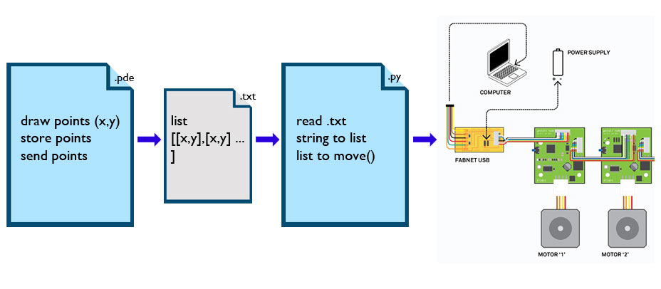
Gabriela, Dani and I were in charge of the code.
Initially, we wanted to create a python application that would analyse an image and give us a G-code path that could than be transformed in moving information for the x and y stages.
After discussion, due to the size of the drops (around 1 cm diameter) and the limited size of the canvas, we realised that the 'images' we would have obtained would have been of low resolution, so we decided to concentrate on simple patterns like lines, curves etc. In addition, due to our limited python skills we actually broke down the code tasks in smaller, simpler and more familiar tasks.
- in processing: create a sketch that generates points(x,y)
- in processing: store points in an array of points [[x,y],[x,y],[x,y]]
- in processing: save as txt file
- in python: open a txt file containing x,y coordinates
- in python: read the txt file and extract values (string to numbers)
- in python: feed the values to the motors
I focused on the python code.
INITIAL 3D DESIGN FOR THE STAGE
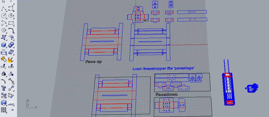
The first step has been to take Nadya's Rhino and grasshopper file and adapt it to our cardboard material (7 mm).
STEPS:
- Changing the material values slider was not enough.
- I 'baked' the files and had to redesign the 2 layers for the scoring (red) and the cutting (blue), cleaning up the extra lines generated during the bake.
- I had adjustef the holes position for the plastic bars supporting the motor, because they didn't fit in the new design
- I then prepared the cut file
- lasercut the first module

TESTING THE FIRST STAGE
Théo took then care of mounting the first stage, and realised that because of the thickness of our material, many of the parts designed by Nadya wouldn't actually work. The walls would be too thick and wouldn't allow the motor to slide in the stage.
He redesigned the cardboard stage and mounted 2 of them for us to start the machine automation process.
HARDWARE: FABNET AND WIRING THE COMPONENTS
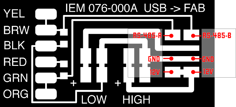
First steps to ge the boards to work is to mill and stuff the FabNET board. In our lab we only had 2 RS-485 usb connectors, therefore we limited the amount of milled boards to 2. Our group didn't make one, we shared the ones made by other 2 groups.
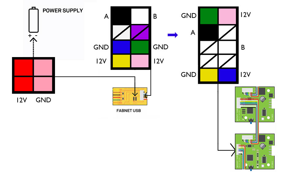
- Fabnet is a multi-drop network, that allows multiple gestalt nodes to communicate through the same wires. Each node is assigned a four-byte IP address which uniquely identifies it over the network.
- It also provides power at two voltages. We used the high voltage (12V - 24V) to drive our motors.
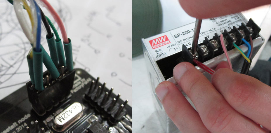
This is the diagram of how the fabnet board connects to a power supply and the gestalt boards.

GESTALT NODES SOFTWARE SETUP
WINDOWS 7 WITH PYTHON 3.4
NOTE: this was a completely failed attempt! It never worked.
STEPS:
- download and unzip nadya's github folder
- In command line I navigated to the downloaded folder and typed the 'python ./setup.py install' command
- It gave me many errors, which I believe are related to the python 3.4 version
- Troubleshooting Python 3.4 install errors with these tutorials:
- Sintax errors
- Sintax errors automated convb
Invalid Sintax Errors I found in my folders:
- the print() function:
'print' statement in version 2.7 changed to
'print()' function in 3.4
- except function :
'except X, T' in verison 2.7 changed to
'except X as T' in 3.4
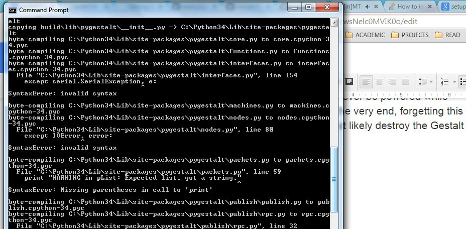
- After fixing these errors I got to these lines on the command prompt...

I was not sure it installed Nadya's pygestalt-package properly, but went on to testing the singlenode.py file...
- I installed the FTDI drivers
- Modified the serial port name in the single node example to my 'COM8' port
- Tried to run the basic code, but didn't work, still getting lots of errors.
At the same time, Dani was following the same steps EASILY on Mac, so I decided to give up and switch to OSX operative system.
MAC WITH PYTHON 2.7.10
STEPS:
- Reinstalled python 2.7.10 release to make sure to have IDLE
- Opened idle

- Downloaded and installed pyserial following this tutorial:
- Download pyserial-2.7.tar.gz (md5) and save it somewhere on the computer
- 'cd' to wherever you downloaded pyserial-2.7.tar.gz
- Issue the following command to unpack the installation folder:
tar -xzf pyserial-2.6.tar.gz
- 'cd' into the pyserial-2.7 folder, then run the command:
sudo python setup.py install
- Tkinter comes already installed in this version of Python
- I installed the FTDI drivers
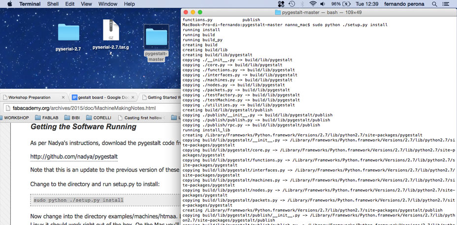
- I Downloaded and unzipped nadya's github folder on the desktop
- In command line I navigated to the downloaded folder and typed the 'sudo python ./setup.py install' command
TESTING SINGLE NODE AND XYPLOTTER EXAMPES

IMPORTANT - in this order:
- CONNECT COMPONENTS WITHOUT CURRENT:
> FABNET TO POWER SUPPLY
> FABNET TO NODE 1
> NODE 1 TO NODE 2
- CONNECT USB TO COMPUTER and identify serial port
- change the serial port to mine in the example files (running in command line 'ls /dev/tty.usb*'to find it)
- SWITCH ON POWER SUPPLY
- RUN CODE IN TERMINAL:
> navigate to the examples>machines>htmaa folder
> run singlenode.py example with 'python singlenode.py' command R
> run xyplotter.py example with 'python xyplotter.py' command R
OBSERVATIONS
When more than one node are attached to the same Fabnet, the command line will ask to identify each node, which is done by pressing the button on the selected node.
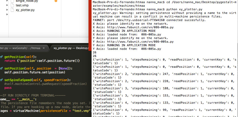
Some files will be created in your folder:
- test.vmp
- motionPladebugfile.txt
- 086-005a.pyc
Sometimes these files give you some problems. The best thing to do is to trash these files and restart the whole system. Every time these files are trashed you will need to re-identify each node.
If you don't plug in USB, power supply etc. in this order you might get errors while running the code, like one of the nodes not being recognised after setup. We recommend to follow these steps.
TESTING GUI INTERFACE FOR GESTALT IN WXPYTHON
Steps followed:
- Download and install wxpython cocoa version (comes as installation application that runs automatically)
- in terminal run:
git clone https://github.com/openp2pdesign/wxGestalt.git (that will clone files to desktop) cd wxGestalt
git submodule update --init gestalt
- now run the wxGestalt.py with command 'python wxGestalt.py'
Although Dani and I were both able to run the file and open the GUI interface, when trying to control our nodes from the interface we had lots of errors coming up (in picture below).
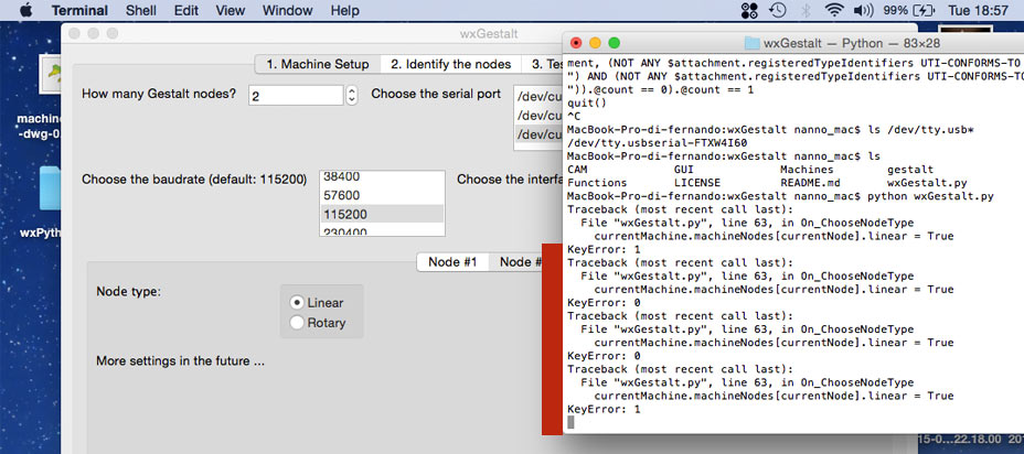
We were interested in testing this example because of the possibility to take an image and transforming it into a path for the motor. However, not being able to understand the issue with the example, we abandoned this test and started planning the code for our machine.
PYTHON CODING STEPS
[ Really simple, but not having worked with python ever before took me ages to figure out ]
To run the drawing machine I to change the hard coded:
moves = [[10,10],[20,20],[10,10],[0,0]]
into:
- loading a textfile containg these x,y information (list of lists)
- reading the information as string
- converting the string into lists of numbers
- numbers into movement
I started by copying Nadyas commands on a textfile.
I defined a new function loadmoves() that imports the file, reads it and returns values.
At the first stage what I read is in a string form and I need to turn it into a list.
I imported the ast library and used ast.literal_eval(line) to evaluate the string.
going from : '[[10,10],[20,20],[10,10],[0,0]]'
to : [[10, 10], [20, 20], [10, 10], [0, 0]]
These new values are the ones that are returned by the loadmoves() and used.
I then tested the new code on the motor and it works great!
OBSERVATIONS:
- It was easier for me to process the string as a long line, without /n interruptions, with bracket at beginning and end, otherwise the literal_eval(line) doesn't digest it. I briefed Gabriela these requirements in the development of the processing sketch
- It's better to close the textfile right after having read it not to mess up with computer memory
- delay between steps is set with time.sleep() function
HARDWARE: FIXING THE 2 STAGES TOGETHER
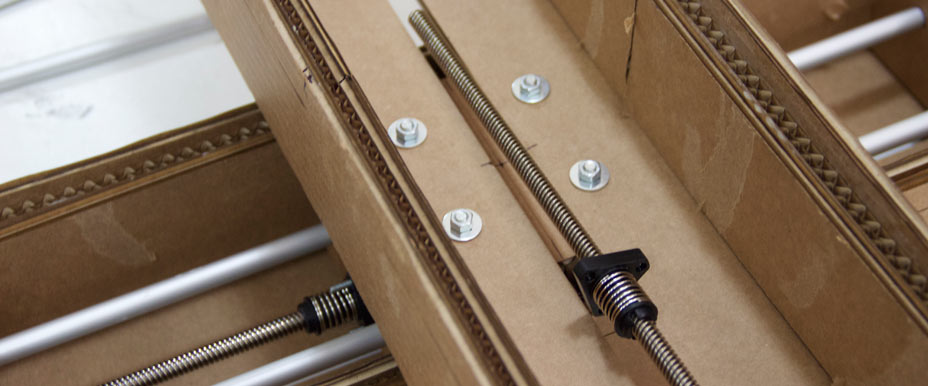
To fix the 2 stages together I used simple washers, bolts and nuts.


HARDWARE: THE DRIPPING
For the dripping system Théo and I cut a little piece of rubber and poked it with a needle. We then fit it into the water bottle lid and sticked the tube in.
FINAL TEST
To test the machines we first looked for the total size of the canvas (e.g. motor moves).
To do so we manually moved the X and Y of the 2 stages to a '0' position, then we tested with incremental moves how many values each stage could take to the furthest position.
We found out that roughly each stage can take values between 0 and 240.
We therefore adjusted the processing canvas to map (x,y)values to a digital canvas of width and height 240.
We then assembled together Gabriela's and my code. I changed the txtfile address to the folder that Gabriela was generating in Processing, with her filename. And we ran the code!
And the group video!
FILES DOWNLOAD LINK
HOME | ABOUT | WORK | CONTACT
Francesca Perona © 2015

This work is licensed under a Creative Commons Attribution-NonCommercial 4.0 International License
Original open source HTML and CSS files
Second HTML and CSS source
Francesca Perona © 2015

This work is licensed under a Creative Commons Attribution-NonCommercial 4.0 International License
Original open source HTML and CSS files
Second HTML and CSS source