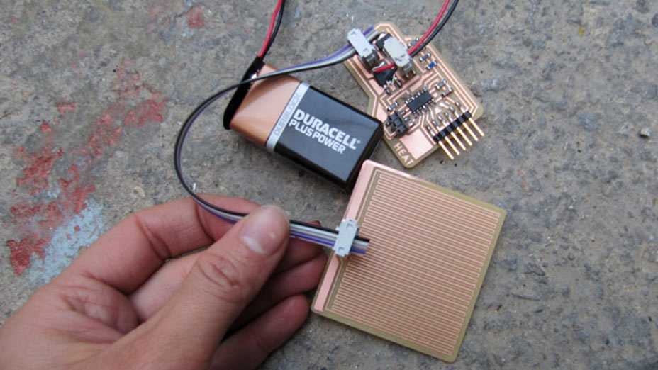
BOARD
This week I designed a board with integrated temperature sensor as input and mosfet circuit as output. The mosfet provides power to a connected 'heating plate' through an external power supply, which produces heat.
I used as a reference the :
- input devices: temperature board
- output devices: shape memory alloy board
- Kobakant's simple heat circuit
BOARD PARTS
1 x ATTINY44SU
1 x 3X2 PIN HEADER (ARVISP SMD)
2 X 2X2 PIN HEADER SMD
1 X FTDI SMD HEADER
1 x CAPACITOR 1 uf
1 X 10 k Ohm RESISTOR RES-US1206FAB
3 X 1 k Ohm RESISTOR RES-US1206FAB
1 X 100 Ohm RESISTOR RES-US1206FAB
1 X PTS12061.0KTC-ND TEMP SENSOR RTD 1 K Ohm 1206 (EAGLE: does not exist but it's same shape of a regular resistor)
1 X RFD16N05LSM9ACT-ND MOSFET N-CHANNEL 50V 16A TO-252AA (EAGLE: NMOSDFETTO252)
1 X ZLDO1117G50DICT-ND IC VOLTAGE REGULATOR 5V 1A SOT223-3 (EAGLE: REGULATORSOT223)
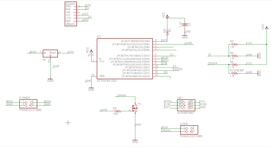
ATTINY44 PINS IN USE:
VCC
PB0
PB1
PB3> RST
PB2> GATE
PA7> (TX)
PA6> MOSI
GND
PA0
PA1> RX
PA2> T2DIFF (1K Ohm res and RTD)
PA3> T1 (2 1K Ohm res)
PA4> SCK
PA5> MISO
BOARD DESIGN NOTES:

1.
I used the biggest mosfet in the inventory, going up to 16 A and 50 V, since creating heating circuits requires quite a lot of power
2.
I would have preferred to use a NTC Thermistor, but in our lab we only have the RTD.
What and Why?
From reference Selecting a Thermistor or RTd:
Generally speaking, NTC thermistors are best for precision temperature measurement, while RTDs are best suited to temperature compensation.
Differences in operation: NTCs: are resistors with a negative temperature coefficient, which means that the resistance decreases with increasing temperature. RTDs: are characterised by a linear positive resistance change with increasing temperature.
3.
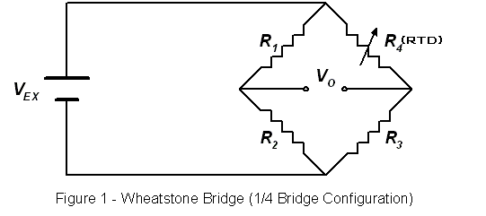
As in Neil's example the Temperature sensor is in a Wheatstone bridge configuration
There are few changes to make: t - hardware: since the RTD we have is 1k Ohm variable resistor, the other 3 resistor composing the bridge should be 1k Ohm too - the python code that interprets the values coming from the RTD is completely different from the NTC (more on this topic will follow)
4.
In the circuit I have a 'VCC' and a 'BIGV': VCC goes to the attiny and temperature sensor and all the parts operating at 5V, BIGV goes from the external power source to the 'LOAD' element (in my case the heating plate).
5.
All the lines going from the external power source to the load and to the voltage regulator are designed in Eagle as thicker (around 1 mm)
6.
I should have left around the voltage regulator and the mosfet more copper, to dissipate the heat produced by the power source.
7.
N channel MOSFET or NPN transistor? Jie uses a N channel Mosfet in her SMA circuit, whereas Kobakant uses a NPN transistor, both are handling a 'load' that draws quite a lot of electricity and I am wondering why they use different components... Doing research on the topic I decided to stick to the MOSFET.
From reference:

The advantage of a MOSFET is this: It requires very little current (almost zero current) into the gate to turn it ON and it can deliver 10 to 50 amps or more to a load. A zener must be added to the gate of a MOSFET if the gate voltage comes from a supply that is above 20V.
*I FORGOT TO ADD THE ZEENER DIODE BETWEEN GATE AND GROUND SO I WILL STAY BELOW 20V*
8.
There is a 100 Ohm resistor between the Attiny pin and the gate, I have seen people using a 10K Ohm one, but it seems like the 100 Ohm resistor works fine.
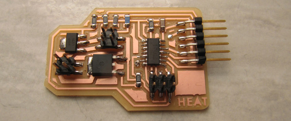
INPUT > ADC IN C :
There are 2 ways of getting sensor data: single ended or differential sensing. The Wheatstone bridge allows us to do Differential sensing between POINT D and POINT B represented in the picture below. The resistors form couples, in which one connects to V and the other to GND. This configuration gives us more accurate values since we are continuously comparing the Voltage change based on the resistance change of the variable resistor couple with the resistance of the other couple at those 2 points.

In Neil's temperature sensor configuration
POINT D = PB3(At45) = ADC3
POINT B = PB4(At45) = ADC2
In C code we are doing a DIFFERENTIAL ADC between these 2 At45 legs and I needed to find 2 legs able to do the same on the At44. I found the solution in the ADMUX - ADC MULTIPLEXER SELECTION REGISTER section of the datasheets.
I used:
POINT D = PA2(At44) = ADC2
POINT B = PA3(At44) = ADC3
In the following paragraphs a description of how does the ADC part of the code changes between At45 and At44:
Neil's code:

My code:

ADMUX: ADC MULTIPLEXER SELECTION REGISTER:
The ADMUX byte has 8 bits which we have to fill in our code:
At44

At45

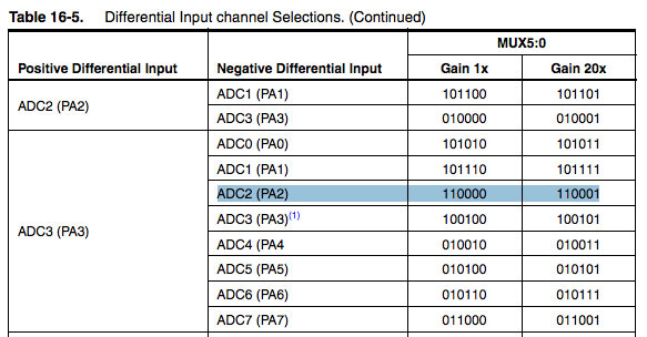
Differential input channel selection:
At45: MUX[3:0] = 0111
with ADC2 used as + differential input
and ADC3 used as - differential input
20X gain
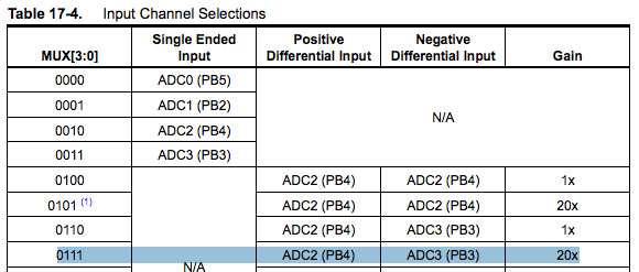
At44: MUX[5:0] = 110001
with ADC3 used as + differential input
and ADC2 used as - differential input
20X gain
Voltage reference selection for ADC:
VCC used as voltage reference
in At45 in bits 7:6,4
REFS2 = X(0)
REFS1 = 0
REFS0 = 0v

in At44 in bits 7:6
REFS1 = 0
REFS0 = 0

ADLAR is the only missing bit, only present in ADMUX in bit 5 in At45.
ADLAR = 0 = results shown as rigth adjusted

On At44 we find ADLAR in ADCSRB
ADLAR = 0 = results shown as rigth adjusted

ADCSRA: ADC CONTROL STATUS AND STATUS REGISTER A:
At45:

At44:

ADEN: ADC enable
At45 Bit 7: ADEN = 1
same as
At44 Bit 7: ADEN = 1

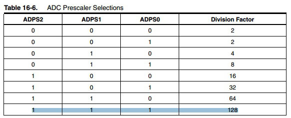
PRESCALER/128
These bits determine the division factor between the system clock frequency and the input clock to the ADC.
At45 bits 2:0 :
ADPS2 = 1
ADPS1 = 1
ADPS0 = 1
same as
At44 bits 2:0 :
ADPS2 = 1
ADPS1 = 1
ADPS0 = 1V
ADCSRB: ADC control status and status Register B
By writing the BIN bit (Bit 7) in the ADCSRB the Bipolar input mode can be selected.
At45 same as At44
BIN = 1

I obviously also had to change the make file, updating it for t44, checking that I am specifying the internal clock at 8MHZ.
INSTALLING NUMPY LIBRARY FOR PYTHON 3.4 ON WINDOWS 7:
In order to run the Python example I needed to download the numpy library.
As suggested by Maurice Op de Beek don't download the regular file proposed by the website. When you are at the download page of numpy, then choose numpy instead of download numpy.zip and
- click Numpy 1.9.2
- numpy-1.9.2-win32-superpack-python3.4.exe (find it here)
- run the installer
This way you don't have to do anything else, it automatically works as soon as you open command prompt!
HELP! FORMULA FOR TEMPERATURE SENSING WITH RTD FOR PYTHON CODE:
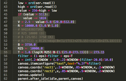
I wish I understood more Maths because I got greatly stuck in this step... The RTD senses differently from the NTC, so I have to chage this part of the code:
RTD follows this formula:

I also gathered (from reference) that:
In the PTS series data sheet, “a” value is 3850 ppm/K. This means that the resistance of the sensor will increase 0.385 Ω for every degree Celsius increase in temperature.
And that the steps that lead to this formula keeping into account the Wheatstone Bridge are (from reference):
VOLTAGE TO RESISTANCE EQUATION:


Keeping into account that in my code my resistors are placed differently and I suppose the formula changes based on the configuration:
For the moment to test the working of the sensor I deleted the whole formula and I am only reading the incoming value:
low = ord(ser.read())
high = ord(ser.read())
value = 256*high + low
OUTPUT > HEATING ELEMENT DESIGN AND TESTING:
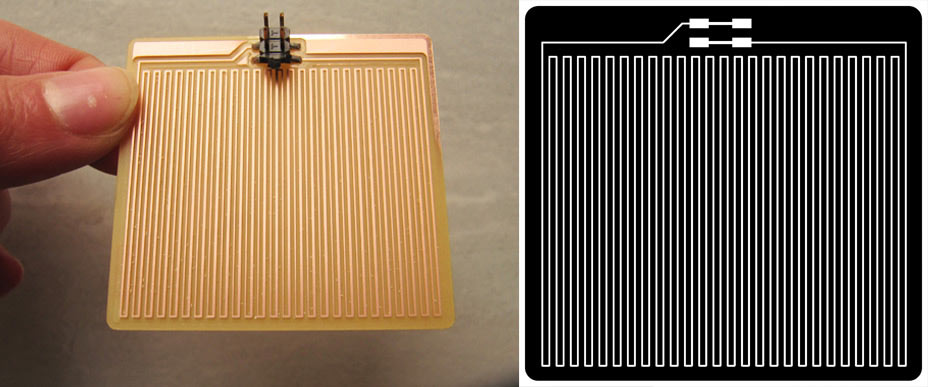
I designed the heating traces with 0.254 thick lines and keeping 16mil as minimum distance between them. The board is around 5x6 cm.
I am using the Mosfet to open and close the access of the heating element to power. Therefore in terms of code, for the moment I only adapted the blink example to 'pulse' electricity to it.
Since copper is a good conductor, I had to design very long and thin lines, with multiple 'bending' points to create resistance. I used as a reference the pcb trace resistance calculator, to get an idea of the values that I would get. I then used a multimeter to test the total resistance of the heating board, which is around 7 Ohms... Not much.

At the moment I am powering the board with a 9 volts battery, and through touch one can really feel the change in temperature on skin (without burning!). A more powerful power supply will increase the effect.
I also ran the same test with the 9 volts battery, but connecting a 6 ply conductive thread (around 20 cm long) to the mosfet, and this heats up in the same way. The material is stainless steel, which is basically a quite resistive material. The extra thick thread has a resistance of about 1.4 Ohms x 30 cm. So I can use quite a long thread to produce bigger resistance!
FOLLOWING STEPS:
The idea is that by having accurate temperature measurements from the temperature sensor, I would be able to control the heat quite precisely, by opening and closing the Mosfet.
There are a variety of materials which react to very different temperature ranges. Expancel, thermochromics, liquid crystals, shrinking hydrogels are some examples. SMA also heat up when actuated, and being able to precisely know the temperature of the wire would improve the control over it.In addition, the design of the heating traces can become quite complex and make interesting patterns...
Unluckily in our lab we only had a thermochromic paint that changed colour at 15 degrees (bright magenta turns white at higher temperatures). I kept it in the fridge and tried to show the effect with a video, but as soon as the material leaves the fridge it cools down and drops the colour.
I think I will investigate further the potential of this circuit for my final project. And I'll get some thermochromics that respond at higher temperatures, Hallcrest has 31°c and 47°c responsive chromics for example.
CODE JOY! ATTINY INTERRUPT FUNCTION
Thanks to the enormous help of Guillem Camprodon, I have been able to put together in C some code that can handle the mosfet and the temperature sensor at the same time.
I initially used as a reference the Blink without delay example from Arduino playground. Since initially my mosfet was turning on and off thanks to a delay, and since anything else added to the main void would have actually frozen during the delay, I needed to be find a way to run in parallel the 2 processes.
Using the millis() function in Arduino allows to control the blinking of the LED without the need of a delay. Implementing a similar feature in C was no joy. We basically had to reverse engineered the Arduino core libraries written to handle attiny microprocessors, looking for a way to implement a count in C.
To do so we need to :
- include avr/interrupt.h
- define sbi prescalers and interrupts
The basic clock that we are using to control the mosfet and we reset at each complete cycle:
ISR(TIM0_OVF_vect)//interrupt
{ countTime++;}
The setup interrupt function we need to define and then callin main:
int setupInterrupts(void) {
// this needs to be called before setup() or some functions won't work here
sei();
sbi(TCCR0B, CS01);
sbi(TCCR0B, CS00);
sbi(TIMSK0, TOIE0);
}
FILES DOWNLOAD LINK
HOME | ABOUT | WORK | CONTACT
Francesca Perona © 2015

This work is licensed under a Creative Commons Attribution-NonCommercial 4.0 International License
Original open source HTML and CSS files
Second HTML and CSS source
Francesca Perona © 2015

This work is licensed under a Creative Commons Attribution-NonCommercial 4.0 International License
Original open source HTML and CSS files
Second HTML and CSS source