ARDUINO PROGRAMMING TOOLCHAIN SOFTWARE (in Windows)
Please go week 6 for instructions/example of working with Arduino IDE on Mac. Since I am working with Firefly (Windows only program), I installed and ran Arduino IDE on WIndows too. LET ME TELL YOU 1 THING - IT'S A NIGHTMARE! If you can, stay on Linux or OS X.
- Install the Arduino IDE 1.6
- Install Arduino Uno drivers XP or Windows7 for USB to serial converter. What will happen trying to connect the Arduino is that the IDE will not give you the option of a serial port to use (which should appera as COM1, COM2 ... In my case COM7).
- Install Attiny Board files for Arduino 1.6 . I followed this tutorial to move them to the right folder. They are needed because otherwise the Arduino IDE would not give you the options for ATTINY microprocessor.
- Install virtual com port drivers to use the FTDI as serial converter.
- Install the Windows 32bit USBtinyISP drivers or 64bit ones for the FabIsp programmer. Tutorial here.
If you open you Device Manager in Windows, you should see something like this (on the right)
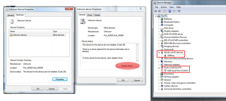
but most likely you will have to manually address the 'Unknown devices' to the right drivers.
Here's how to:
Where Arduino board will appear: Ports (COM&LPT) in device manager.
Where to find Arduino drivers: Documents > arduino-1.6.0 > drivers > FTDI USB Drivers
Where USBtiny (fabisp) will appear: under 'Universal Serial Bus controllers'
Where to find drivers: Save the downloaded FabISP drivers in a folder you will rememeber. I created a subfolder called 'Drivers' in my Documents folder. The folder should look something like 'usbtinyisp_libusb-win32-1.2.1.0'
PROGRAMMING HELLO BOARD WITH FABISP IN ARDUINO IDE
I first run some tests with the Arduino to check everything works, then went on to program with the Attiny.
The steps are the same as for Mac OS:
TOOLS> BOARD> attiny
TOOLS> CLOCK> 20 MH
TOOLS> PROCESSOR> ATTINY44
TOOLS> PORT> my .cuusbserial port
TOOLS> PROGRAMMER> USBtinyISP
TOOLS> BURNLOADER
BUT I encountered lots of problems when programming the helloboard in Windows with Arduino IDE. Sometimes uploading the code to the board works fine. But most of the times I get this error message:
avrdude: verification error, first mismatch at byte 0x02c0
0xff != 0x04
avrdude: verification error; content mismatch
Somehow the Arduino avrdude is having problems. Despite this error sometimes I am able to upload code to the board anyways, but sometimes not...
I tried to:
- change the FTDI and USB cables
- invert the usb ports (I only have 2 so can't test any other)
- readdress the drivers
- burning the bootloader everytime sometimes helps, but sometimes not.
- Then I tried to program the board on other Windows machines, and I seem to be able to upload the code without problems...
- And tried to program the board on Mac and I am not having problems either.
So I am concluding that there might be some problems with my USB port on the Mac, or some problems with Bootcamp (I have my Mac partitioned for Windows).
Solution: I am doing all the programming in OS X on another Mac (luckily I have 2 Macs, the old grandpa is much more reliable than the new one), and then plug it in the other computer on Windows partition to communicate via Serial with Firefly when needed. That seems to work fine.
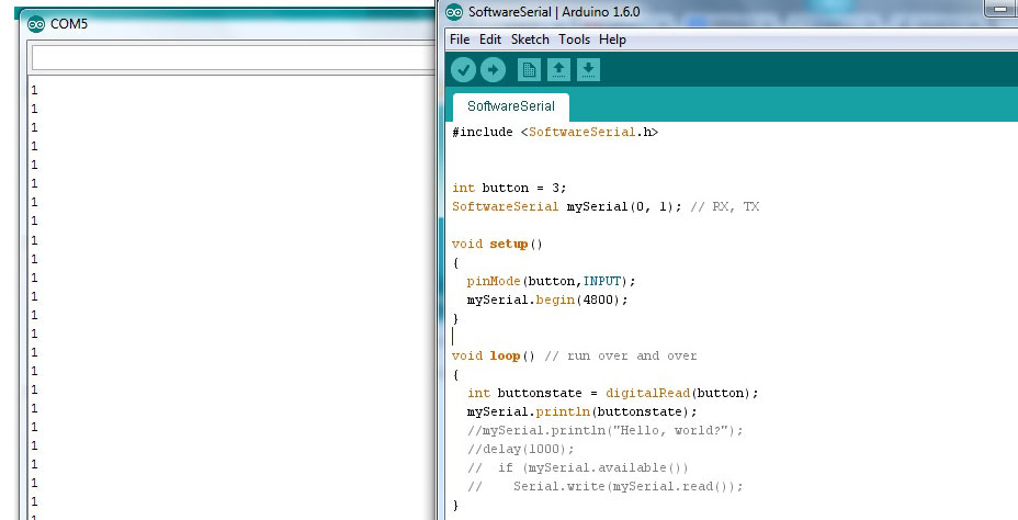
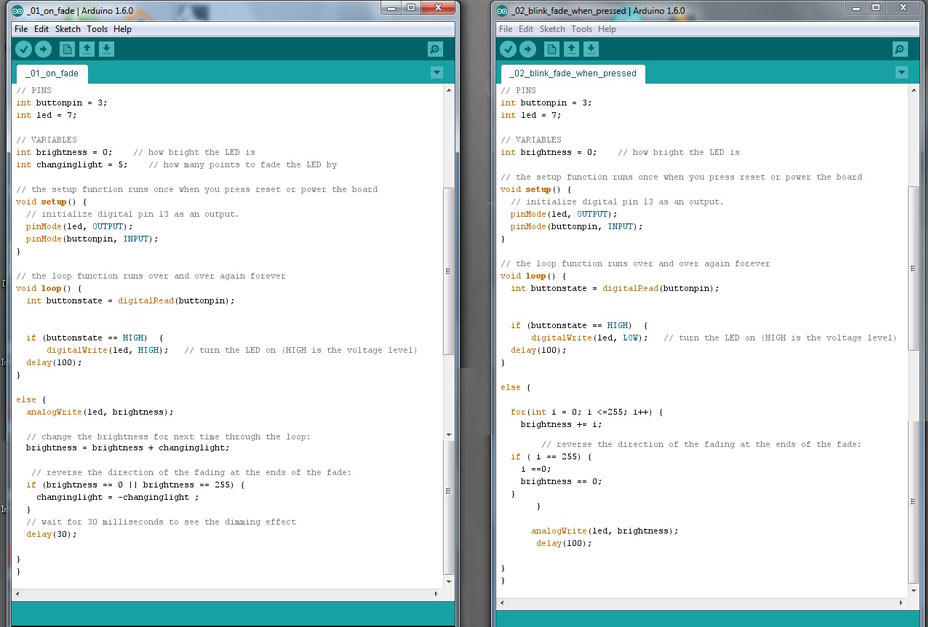
Here are some examples I wrote for the Hello Board in Arduino that will be use:
1. softwareserial:
listen to the button on Serial port
2. on_fade
when button pressed led fades (if statement)
3. blink_fade_when_pressed:
when button pressed led blinks/fades (for statement)
ATTINY44A VS ARDUINO PINS
These images are fundamental for any programming with the ATTINY in Arduino IDE:
Attiny LEGS description:
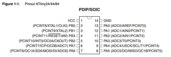
and Attiny - Arduino pins correspondance:

ATTINY LEGS AS PWM (ANALOG OUTPUT):
LEG 8 (Arduino pin 5)
LEG 7 (Arduino pin 6)
LEG 6 (Arduino pin 7)
LEG 5 (Arduino pin 8)
ATTINY LEGS AS ANALOG INPUT:
LEG 6 (Arduino pin 7)
LEG 7 (Arduino pin 6)
LEG 8 (Arduino pin 5)
LEG 9 (Arduino pin 4)
LEG 10 (Arduino pin 3)
LEG 11 (Arduino pin 2)
LEG 12 (Arduino pin 1)
LEG 13 (Arduino pin 0)
ATTINY LEGS AS DIGITAL INPUT/OUTPUT:
LEG 2 (Arduino pin 10)
LEG 3 (Arduino pin 9)
LEG 5 (Arduino pin 8)
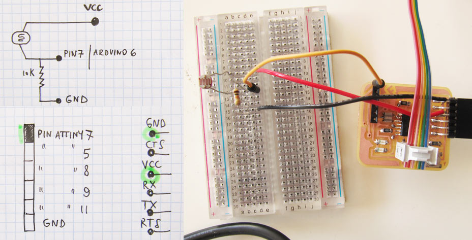
HELLO BOARD WITH 2 SENSORS
In my Hello Board design:
LEG 13 (Arduino pin 0) : RX
LEG 12 (Arduino pin 1) : TX
LEG 06 (Arduino pin 7) : LED
LEG 10 (Arduino pin 3) : BUTTON
LEG 11 (Arduino pin 2) : LIGHT SENSOR (added)
ATTINY AND FIREFLY
Software needed:
- Rhino
- Grasshopper
- Arduino Ide
- Firefly
- follow instructions at Intro to Firefly chapter 2.2 to get the toolbar up and running
Firefly is a toobox that lets Grasshopper communicate with the Arduino IDE and Arduino boards via Serial Communication.
Exactly. ARDUINO BOARDS.
It's a little more complicated to set it up for ATTINY.
One of the first steps after downloading Firefly is to Upload on your Arduino board the Firefly_UNO_firmata sketch that was automatically downloaded in your Arduino folder. This code will set up all the pins on the Arduino Uno so that they can communicate back and forth with Grasshopper.
You won't be able to do this for the ATTINY for many reason:
1. it's memory is too small to contain the file
2. the file is written for the Arduino Uno pins and specifications, so won't work anyways.
One solution would be to make the Fabduino board, and it should be easy to configure it for Firefly. But for now let's stick to the Attiny and try to make it work!
To use Firefly we will stick to the objects:
- Serial Read (generic)
- Serial Write (generic)
And in the Arduino IDE we will simply use the SoftwareSerial library to communicate via Serial Port with Grasshopper.
This week I concentrated on:
- Sending to Grasshopper 2 input sensors data via SerialPort with Arduino code (in Arduino IDE)
- Sending from Grasshopper data to a LED output via SerialPort with Arduino code (in Arduino IDE)
1. RECEIVE SERIAL DATA FROM 1 SENSOR INPUT IN GRASSHOPPER:
This is the sketch to set up Grasshopper to see ports, and open/close port to read from Serial.
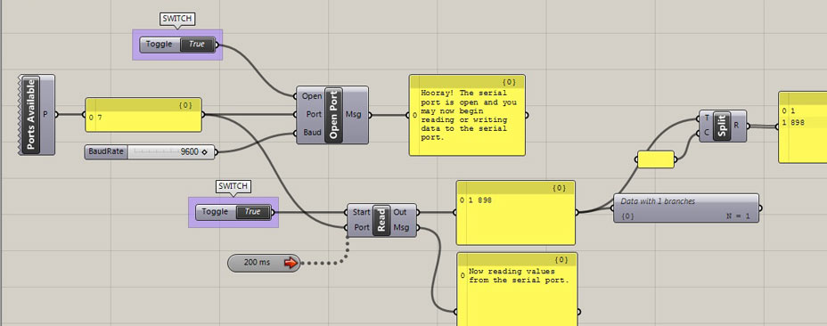
And the corresponding Arduino Sketch would be:
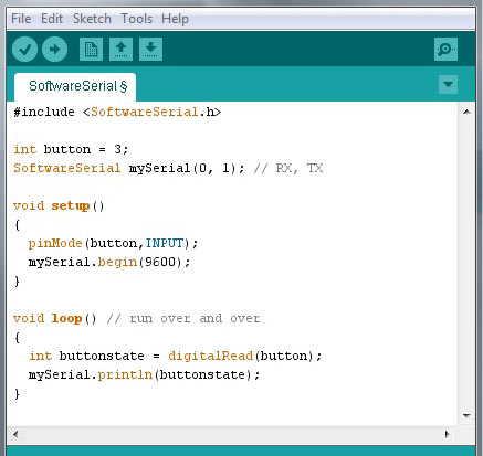
NOTES:
- Port available component (Firefly>Arduino Boards>Ports Available) returns an int vlaue indicating available serial ports(should be the same as the serial designated in the Arduino IDE).
- Open/Close Port (Firefly>Arduino Boards>Open/Close Port) component + Boolean Toggle (Params>Special>Boolean Toggle): when double clicking on toggle opens port and lets stream of data in. First close Arduino serial port window, if open.
- Serial Read object reads all of the analog and digital sensor information from the board.
- Baud Rates between Grasshopper and Arduino sketch need to correspond.
- We need to refresh our Grasshopper sketch, done by connectin a Time object.
2. RECEIVE SERIAL DATA FROM 2 SENSOR INPUTS IN GRASSHOPPER:
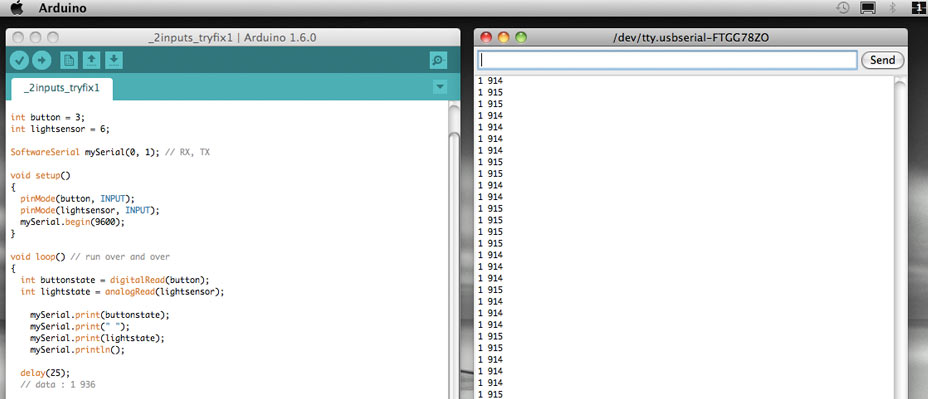
When sending data from Serial to Grasshopper we basically send a string, with 2 sets of data: sensor 1 data and sensor 2 data. We therefore need to find the best way to send a string, and break it into the 2 sets of data.
To do so in Arduino we structure the serial data this way:
mySerial.print(buttonstate); //first data stream
mySerial.print(" "); //add a space between the two data streams (could also be a comma)
mySerial.print(lightstate); //second data stream
mySerial.println(); // new line
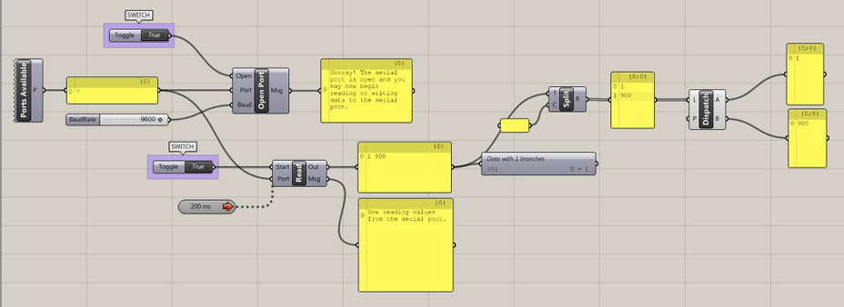
And in Grasshopper we use the "Text split" object to break down our string.
The object takes a Separator (C) element, which in our case is the space btween the 2 values.
We then use a dispatch element to divide the 2 sets of data.
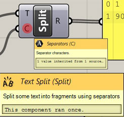
TIPS:
> Open Serial Port window in Arduino IDE first to check if data is flowing
> Always close serial port window in Arduino IDE before opening port in Grasshopper
3. USE DATA RECEIVED THROUGH SERIAL PORT TO CONTROL OUTPUT (LED):
The next step is to get the opposite running: sending data from Firefly to Serial Port, and use these values to 'write' the brightness of our LED.
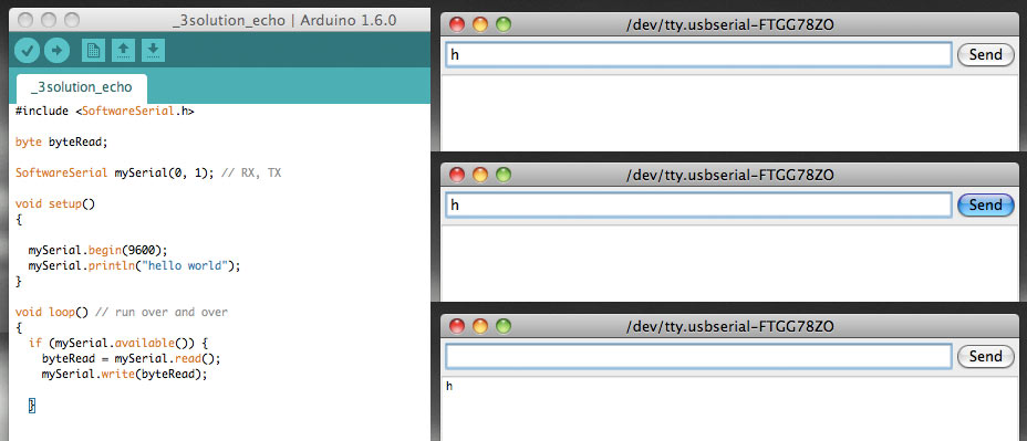
1. First I need some read/listen system running on the board, like the 'hello echo' example written by Neil for C programming.
REFERENCES:
- Software Serial Example
- Byte to int conversion
- Simple Arduino Serial tutorial
FROM REF:
" pins are used as virtual RX and TX serial lines. The virtual RX pin is set up to listen for anything coming in on via the main serial line, and to then echo that data out the virtual TX line. Conversely, anything received on the virtual RX is sent out over the hardware TX."
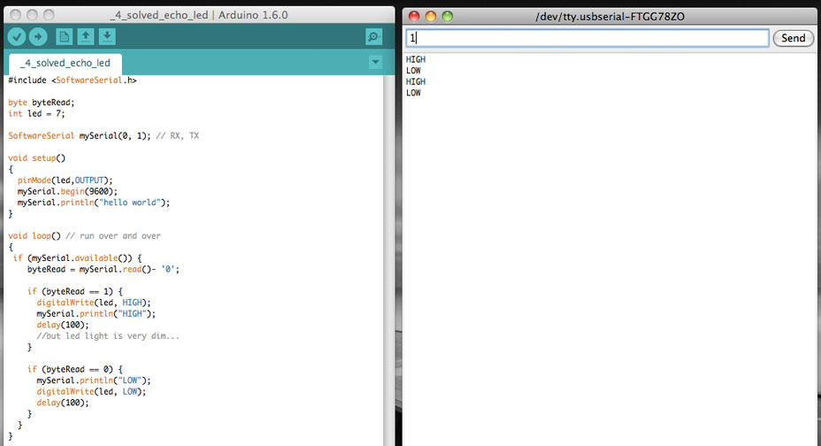
2. Then I need to be able to use this data to switch on and off an LED.
NOTES:
When we do byteRead = mySerial.read() we get a byte, therefore the data is NOT seen by the program as an int value. To obtain int values we need to convert string to integer.
It is enough to add - '0' :
byteRead = mySerial.read()- '0';
to get the conversion.
What happens now is that:
if I press 1 and send it through serial, led goes HIGH,
if I press 0 and send it through serial, led goes LOW.
3. Then I need to be able to write in Serial port values like "255", and use this value to control the brightness of the LED. Since 255 is 3 bytes, I need to create a String to whom I can append values until a certain command (like tab, or space), and then send the value to the LED.
I will be following this tutorial .
NOTES:
- The SoftwareSerial library has some limitations. In my experience so far, the ATTINY doesn't always like the command line: if (mySerial.available())
- Later I found Andy Paine's short explaination of how other boards work with Firefly. Have a look, but is basically what I explained so far.
NEXT STEPS:
- Read and send data at the same time
- Make a Fabduino
- test if problem on Windows is caused by 32 bit Windows drivers
CLEARING SOME DOUBTS
I've been working with Arduino for a while now. I'm definitely not a proficient nor prolific coder, but I can get what I want after hours of scratching my forehead. But I never had a clue of what's behind this interface, why is it considered 'simpler'... So it's good for me to put down some points.
1.
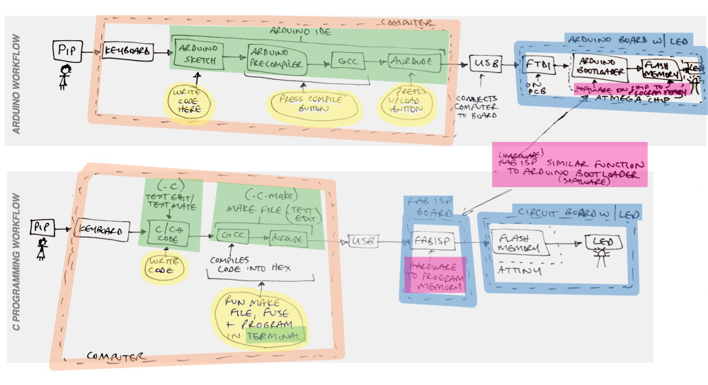
Arduino is based on C, but unlike C, a series of friendly libraries hides and processes the hard core stuff for you. This wonderful sketch shows the Arduino workflow and the C workflow.
2.
When we write a sketch in Arduino IDE, we end up with a single textfile.ino
When we write in C language we proceed to create:
file.c
file.make
file.hex
file.out
We write our instructions in the .c and .make files. The .c file is what corresponds more or less to what we code in our Arduino IDE, instructions on what pins we are using, input/output, on/off, if and else statements...etc
The .make file includes instead specific information about our microprocessor (mcu, number of fuses... etc) and how to proceed in the next steps.
We then need a COMPILER to turn this code into a .hex file, which looks like this:
:1000000010C02AC029C028C027C026C025C024C0CF
:1000100023C022C021C020C01FC01EC01DC01CC0E4
:100020001BC011241FBECFE5D1E0DEBFCDBF10E065
And the .out file, which looks like this:
7f45 4c46 0101 0100 0000 0000 0000 0000
0200 5300 0100 0000 0000 0000 3400 0000
8403 0000 8200 0000 3400 2000 0300 2800
We use a GCC (GNU Compiler Collection) because it's a free compiler system. We invoke a language-specific driver program (gcc for C in this case), which interprets our code, calls the actual compiler and runs the assembler on the output, and then optionally runs the linker to produce a complete executable binary file. AVRDUDE is a command line program (works in both terminal on linux and OS X, and command prompt in Windows) to tell which board we are programming, the port we are using to communicate, the programmer type, baudrate... We are actually shortcutting this with out makefile, which already contains all specifications.
We only run the command line:
make -f "name_of_our_file.make" program-usbtiny
Which:
- creates our file.hex and file.out
- identifies and erases the memory on the chip
- writes the binary file to our ATTINY
- verifies it
The Arduino IDE works in a similar way, with GCC and AVRDUDE, but these processes are called independently while compiling and exporting the code.
3.
Arduino cleraly allows us not to worry about the microcontroller we are using when writing out instructions: whatever you write is compiled on the Arduino IDE for the specific microprocessor. Arduino boards gennerally use the ATMEL family microprocessors,
whereas we use the ATTINY family microprocessors (much smaller, less powerful), in this case the ATTINY44.
This is why we need to add the ATTINY specifications folder in Arduino> hardware.
Writing C code, we need to specify these in the .make file or AVRDUDE commands.
C PROGRAMMING TOOLCHAIN SOFTWARE (in windows)
The toolchain software needed to program in Windows is:
- WINAVR (GCC compiler for Windows)
- 32 or 64 bits usbisptinydrivers for the FabISP programmer
- FTDI to virtual serial converter drivers for the hello board
- a decent texteditor like Sublimetext
ECHO on HELLO BOARD
I copied first Neil's Echo Hello example files in a folder:
- hello.ftdi.44.echo.c
- hello.ftdi.44.echo.c.make
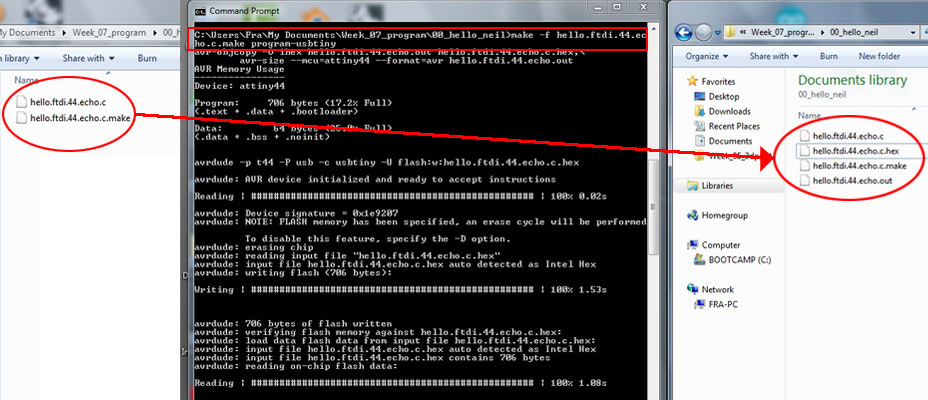
Then opened Command prompt on Windows and navigated to the folder:
cd "My documents\Week_07_program\hello_neil
Here I typed the magic command
make -f "hello.ftdi.44.echo.c.make" program-usbtiny
And the .hex and .out files were created in my folder
And the code uploaded to the board.
Opening in Arduino the Serial Port window
typing a character in it
pressing send
I can see that the board responds to me typing "h" with "hello.ftdi.44.echo.c:you typed "h".
THE CODE:
The functions defined before the main void are.
- void get_char(volatile unsigned char *pins, unsigned char pin, char *rxbyte)
which received (rxbyte) on the pin the character
- void put_char(volatile unsigned char *port, unsigned char pin, char txchar)
which sends the character to the port
- void put_string(volatile unsigned char *port, unsigned char pin, char *str)
which prints an empty string to be filled in the main void.
The main void:
- gets the character
- writes the string with the character and goes to new line on serial port
BLINK A LED on HELLO BOARD
For this example I started from the files:
- hello.arduino.328P.blink.c
- hello.arduino.328P.blink.make
I soon realised when trying to compile the file, that AVRDUDE woldn't let me because it would find errors.
In the file.make I realised I had to:
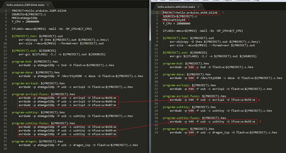
1.change the first line to the appropriate name of the file
2. change the MMCU
3. change all the references to "atmega328p" to "t44"
4. change the fuses name
In the .c file I had to think a bit more.

Reading the datasheet I found that the legs of the ATTINY are defined differently from Arduino IDE.
In my hello board the LED is placed on PIN 6 = PA7.
And that the port that takes care of it is PORTA, direction DDRA.
The rest of the code is the same.
BLINK WHEN PRESSING BUTTON on HELLO BOARD
For this code I followed 3 examples:
- blinkOnButton.c
- hello.button.c
- hello.ftdi.44.echo.c

In this example I am adding a button and listening through the serial port to the data sent by the button (0 and 1).
I therefore need to define:
- an input object with
#define input(directions, pin)
- add serial communication specs
#define bit_delay_time 102
...
- set input pin to PA3 since my button is attached to leg 10 = PA3
#define input_port PORTA
#define input_direction DDRA
#define input_pin (1 << PA3)
#define input_pins PINA
- define serial port communication, copied from the hello.ftdi.44.echo.c, where I was using PA0 and PA1 for RX and TX. In this case we only use one leg because we are only sending data to the serial port, not receiving.
#define serial_port PORTA
#define serial_direction DDRA
#define serial_pin_out (1 << PA1)
- create a void put_char function that takes care of retreiving the data
- in main void we initialise the new functionalities:
set(input_port, input_pin); //button
input(input_direction, input_pin);
set(serial_port, serial_pin_out); //serial communication
output(serial_direction, serial_pin_out);
- in main void we move the code to switch on the led:
set(led_port, led_pin); = pinMode(led, HIGH);
inside a "while" statement that determines when button is pressed
while (0 != pin_test(input_pins, input_pin));
and sending the value
put_char(&serial_port, serial_pin_out, '1');
- in main void we move the code to switch off the led:
clear(led_port, led_pin); = pinMode(led, LOW);
inside a "while" statement that determines when button is not pressed
while (0 == pin_test(input_pins, input_pin));
and sending the value
put_char(&serial_port, serial_pin_out, '0');
FILES DOWNLOAD LINK
HOME | ABOUT | WORK | CONTACT
Francesca Perona © 2015

This work is licensed under a Creative Commons Attribution-NonCommercial 4.0 International License
Original open source HTML and CSS files
Second HTML and CSS source
Francesca Perona © 2015

This work is licensed under a Creative Commons Attribution-NonCommercial 4.0 International License
Original open source HTML and CSS files
Second HTML and CSS source