3D SCANNING
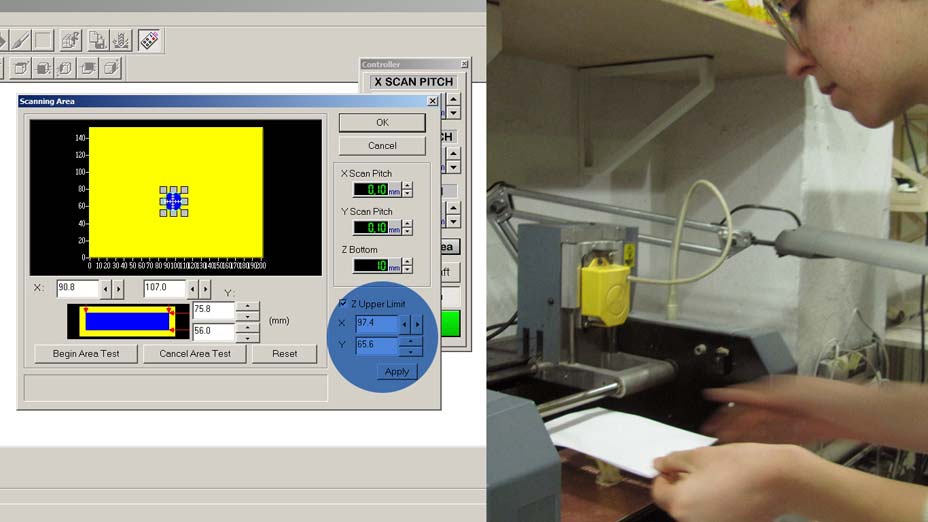
For the scanning process I wanted to scan in high resolution the texture of an object. I love the fractal like surface of romanesco cauliflowers, so I decided to give it a try on the Modela. The software to be used with this machine is the Dr.PICSA sotware. It's pretty straight-forward and there are few variables to set:
On the controller window we can set:
- SCAN PITCH (scanning resolution) on the x and y axis; in my case it was set to 0.05mm on both
- Z BOTTOM: the lowest point the tip should reach (particularly useful for objects that need to be scanned on both sides)
Opening the SCANNING AREA window we can set the area of the base that we want to scan.
We can adjust the blue rectangle (scanning area) to surround our object by dragging the arrow that appears on the perimeter of the rectangle.
To test the position we can double click each corner, and the head will move and drop the tip to that point to show how it corresponds to the screen settings.
After setting our area we can adjust the Z UPPER LIMIT:
a light blue circle will appear on our rectangle. If we drag it to the center (or roughly highest point of our object) and then place a sheet of paper on top of our object, when we double click it, the tip will drop to touch the paper sheet and set the maximum height.
At this point we are ready to scan our object.
The Modela head will gently touch the surface of our object in the x and y direction, and depending on the resolution of our scan, it will save point cloud data that will be used to generate and STL file.
SCANNING TIPS & FAILURES
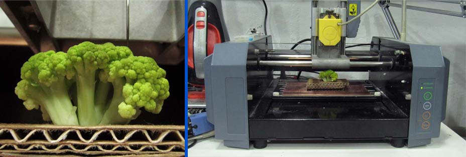
- Carefully select the scanning area and resolution. For my scan I chose a very small area (some 2 x2 cm area) with a very high resolution. - Attach the object steadily to the Modela base, or the tip, while scanning, might move your object.
My first scan went wrong because the cauliflower was not steady enough, so I had to make sort of a cardboard frame where I inserted my floret, and taped the cardboard base to the Modela base.
- 'Alive' objects are not recommended.
In my experiment the cauliflower floret opened up at night, changing its original shape and modifying the selected area. The Modela tip therefore 'pierced' the surface in a couple of points (worsened by the fact that I didn't select a bottom scan Z I suppose). Although in the second scanning attempt I obtained a complete scan of the object, the result was very disappointing. Although the Modela head is really gentle when testing the surface, it was pulling slightly the florets subparts, generating a very jagged model.
- Beware, fellow students might attack your cauliflower and demand bits of it to fill their stomach.
REPAIRING THE 3D MODEL

I then opened the 3D scan in Blender. I smoothed various time the surface vertexes, decreased the spikes, and generated a closed model.
3D DESIGN & PRINTING SOFT AND FLEXIBLE SURFACES on MAKERBOT
Since my background is in textiles and my research focuses on soft structures, for the 3D printing part of this week assignment I concentrated on generating flexible surfaces.
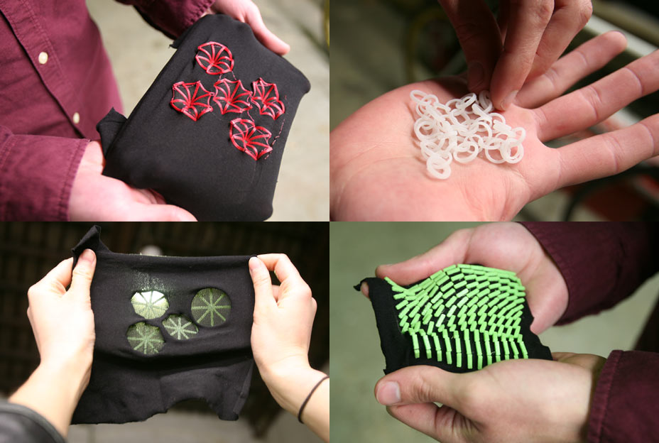
My first test has been to print simple patterns onto a stretchy lycra base to observe the reaction of the substrate to the shapes and nature of the material printed.
I designed simple disks (around 4 cm diameter and 1.5/2 mm thickness) with intersections encountering in the center of the geometry, to test whether the whole surface would have created a mountain in the central point. I created variations of the pattern, one in which the shapes were broken, one where they were continuous. It turned out the broken shapes allowed more movement and more interesting effects. Breaking the connections at the center of the disk also provides better 3 dimensional effects.
- It can be observed that the area contained in the disks
remains very tense after releasing the surface, due to the rigidity of the printed material above.
- The broken circles create an interesitng relief pattern, that can most definitely be controlled.

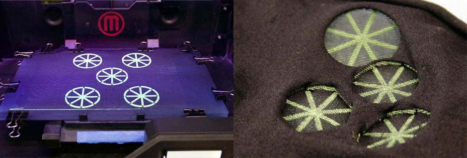
I then ran a very similar test in Ninjaflex filament.


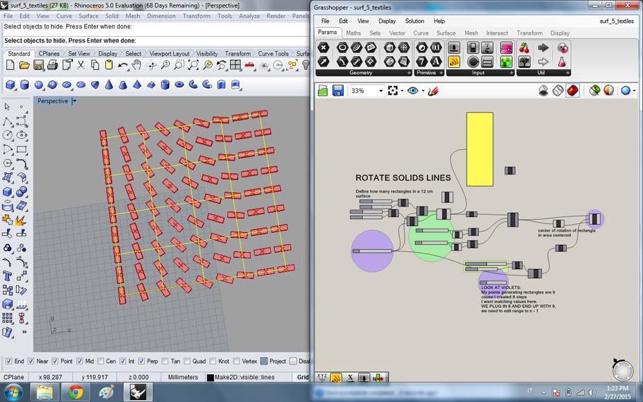
I also designed a small rectangular featured grid, with elements in progressively rotating orientation, from 0 to 90 degrees angle. Since the definition is parametric various elements of the design can be varied:
- range of rotation
- number of features
- width, height, thickness of features.
In this tests the rectangles are 2 mm thick, 2 mm wide and 8 mm long.
In the points where the geometries are almost in line, the surface shows an interesting curvature. The effect is due to the fact that when releasing the tense lycra from the 3d printing plate, the shapes ends touch, forcing the structure to bend under this effect. In the points where the geometries are parallel, the surface behaves plainly.
Further work on this experiment might generate very interesting results.

PLA SETTINGS:
100% fill
no rafts nor support
standard temperature
standard speed
NINJAFLEX SETTINGS:
100% fill
no rafts nor support
temperature 245°
speed 15 mm/s
EXPORTING THE STL FILE
Things to check:
- size
- non manifold geometry to correct
- holes to fill
- normals on the right direction
- smoothness of model
- size of STL file (above 250 meg forget it)
MAKERBOT GCODE GENERATION
The Makerbot software is pretty easy to use.
- Select your printer
- Add file
- Move object to platform. If everything is right, the file will be the size you expect and fit in the base. I had to slightly resize one of my models to fit in the base (option provided by the program). - Scale or rotate in case of need
- SETTINGS:
- Choose MATERIAL: Makerbot prints well PLA and Flexible filament
- Choose if to generate RAFTS
Rafts are very useful in case of complex objects. A raft is a very loose 2 layers base generated by the software, that 'prepares' a better bed for the object to be printed. Since big obects tend to stick to the Makerbot plate, a raft is very useful to also remove the object from the base.
- Choose if to generate SUPPORTS. Supports are necessary for complex objects with overhangs. Definitely not the case of this design.
- Choose resolution ( I used standard)
- Choose INFILL (Since my objects are mainly walls, and very fine, I chose 100% infill)
- Choose LAYER HEIGHT (I left it at 0.20 mm, which means that each layer ofthe printing process will be that thick. For finer designs the thickness can be decreased to achieve better results)
> SAVE SETTINGS
> EXPORT PRINT FILE and save to sd card
SETTING 3D PRINTING PLATE FOR TEXTILES on MAKERBOT
Setting the Makerbot to print on the textile took a bit of tuning.
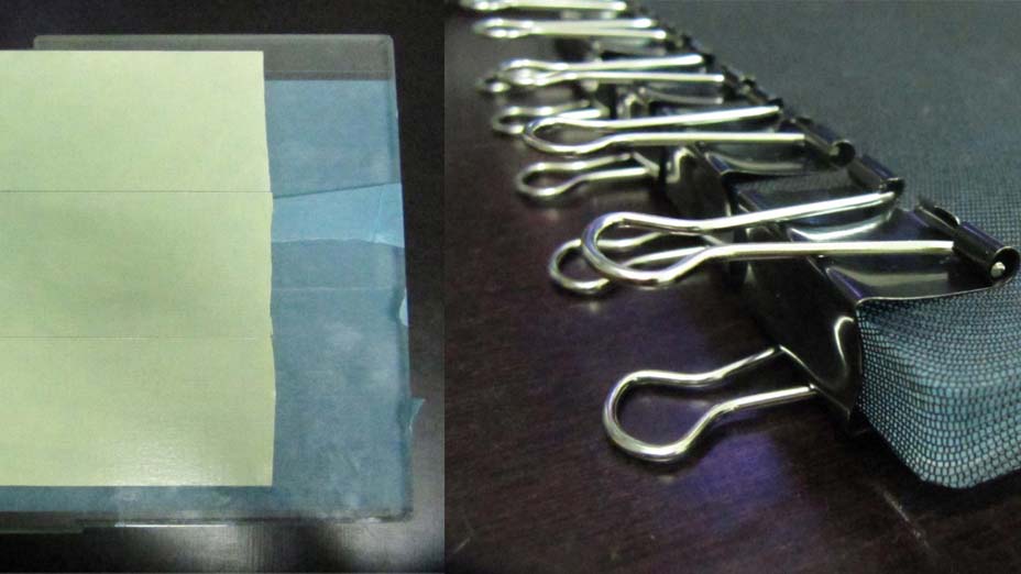
I fixed the lycra base onto the Makerbot base with bulldog clips.
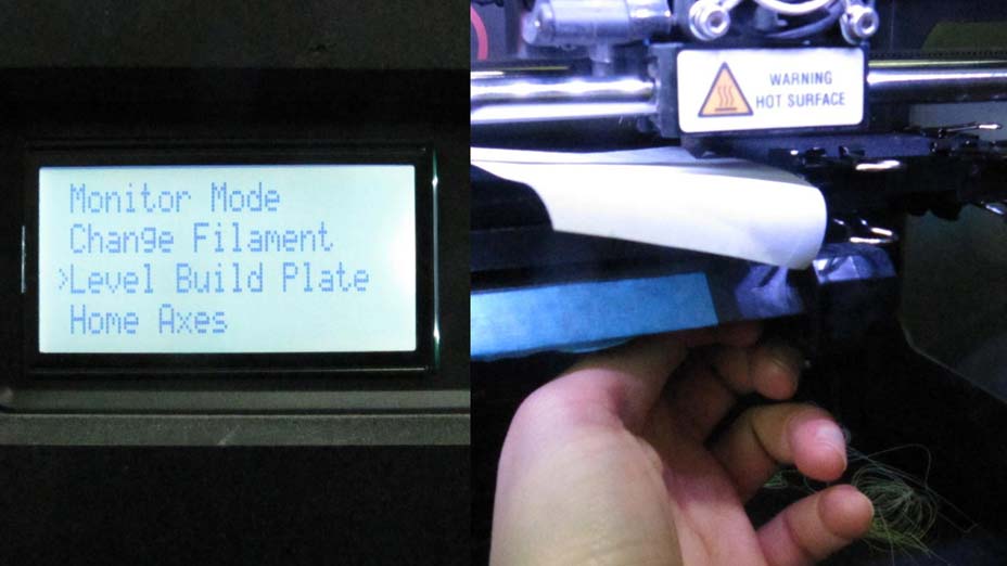
Then I levelled the plate going into UTILITIES > LEVEL BUILD PLATE.
The head will move to 7 different points on the plate. To test the distance of the extruder from your surface use a piece of paper. The paper has to pass between head and base with ease, but you should also feel a little bit of resistance. To adjust the building plate there are 3 screws under the plate, 2 at the front and one at the back. When the spring decompresses, the plate goes up, diminishing the space between plate and head; when it compresses, it goes down, augmenting the space.
The first 3 trials went all WRONG!
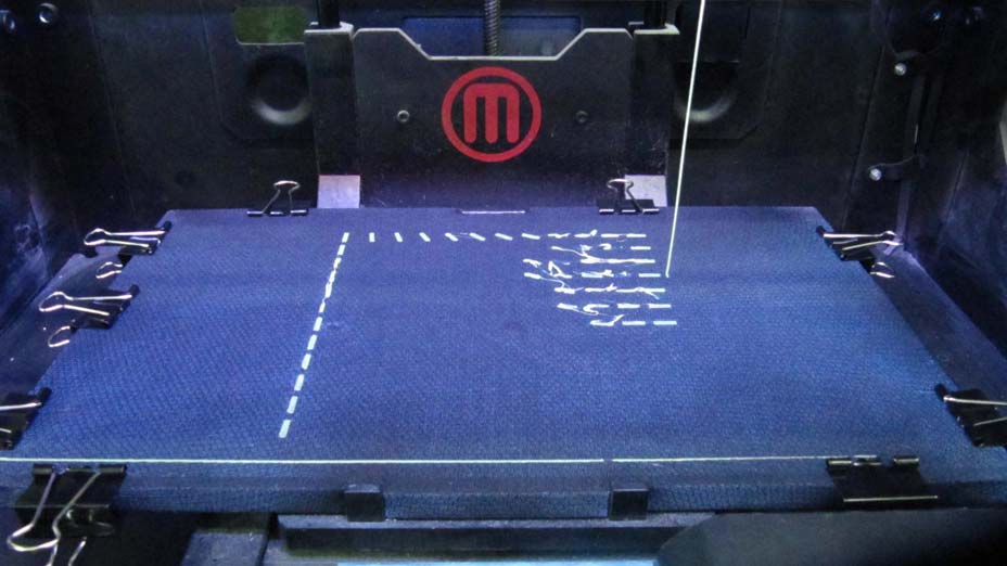
At first the extruder was pulling the surface of the fabric, especially in the central area, which is far from the bulldog clips. This effect made me suppose that I should have levelled the plate with a looser friction to prevent pulling. But the more space between the plate and the head, the less adhesion of the extruded material to the surface, which caused swirly extrusion. The head has to slightly press the material on the surface, filling the gaps between the weaves.
The best solution I found (working perfectly) is to tape with double sided tape the central area of the Makerbot plate, and then attach the VERY tense fabric onto it with the bulldog clips. Press the fabric on the tape to achieve maximum stickiness. Now that the surface is well fixed I can decrease the distance between extruder and plate and print sfely.
To print just go to the main menu and BUILD FROM SD CARD, and choose your model.
The extruder will then heat up and start printing.
TIPS:
- Keep the bulldog clips as mush as possible at the border of the plate, especially at the corners, or the extruder might bump into them.
- The first layer is crucial in this process, if it goes right, SUCCESS!
FUTURE TESTING :
- I will need to find a way of determing how stretched is the lycra surface on my printing base, and to make sure that the direction of the lycra weave is consistent everywhere.
3D PRINTED TEXTILES DESIGN
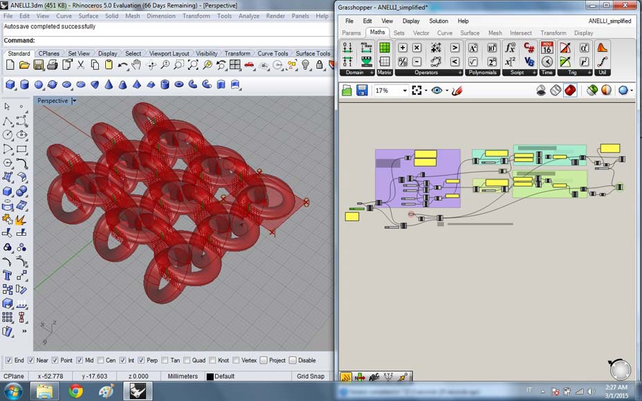
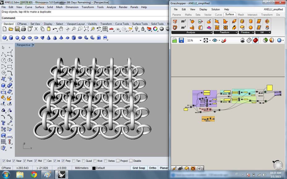
The second experiment involved creating a complex structure, not achievable with subtructive manufacturing. I went onto a long process of trying to design a grasshopper definition of a repeatable module that could than be applied to all kinds of shapes with paneling tools and morph object function.
1. I first created a parametric definition that allowed me to create different curves in a stack, change their size, shape and number and then loft them together to obtain a surface to apply my modules to.
2. PROBLEM: Lofts make Breps components (polysurfaces). But paneling works on subdivisions of single surfaces... So I have been looking for a way of transforming a polysurface in a single surface... In vain up to now.
I then decided to instead use my generated layers in Grasshopper to create a revolve around it. Although the result is less interesting, it is a single surface.
3. I then subdivided the surface with the SURFACEBOX component.
4. I created a module geometry in Rhino, referenced it in Grasshopper and through BBOX and MORPH components I created a bounding boz around the object and applied it to the whole surface.
5. PROBLEM: This operation is quite heavy computationally and the more complex the surface, the easier your computer will crush. I had to give up the idea of making a 10x10x10 object because I could not manage the computation needed.
6. I generated some patterns to test the effects
7. I then decided to work with a torus and create intersections on the panelled surface between the modular elements. I used a flat surface as a starting point, rotating, scaling, moving copies of the MORPH to create linked structures.
8. I then tried to apply the same module to a more complex base surface (round). Calculating the tranlsation vectors and rotation planes for such geometries is still giving me a headache).
9. I decided to print this pattern to test the working of the structure.
Since the Grasshopper definiton is parametric I can keep changing the module and the base surface, which will allow me to create more complex structures in the future.
FORMLABS SETUP AND PRINTING
The model I printed was arond 8 cm x 8 cm x 2cm height.
I used the resin printer because it is the one that allows better definition and generates the better support material structure. The rings were around 1 mm thick and between 5 and 8 mm of diameter.
The Formlabs software is easy to use.
STEPS:
- set object position and size
- orient object on plate
- generate support material
And then send to print.
The printer has signs showing the maximum and minimum amount of resin needed in order to print properly.
Since when starting to print the above plate is immerged in the resin bath, and while printing it moves side to side, the level of material will raise and if the liquid is topped more than the suggested amount it might overflow!
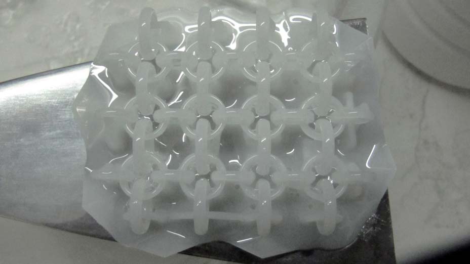
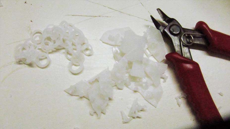
My object was laying flat on the plate, and the settings for the support material were:
Point size: 0.40
Scope: 1.00 mm
Base: Minimum
Height above plate: 3.50 mm
The plate slowly raises from the bath, and layer by layer laser solidifies the resin.
Once finished the print, we need to clean the object in alcohol and remove the support material.
I will upload a separate tutorial for preparing the machine to print and cleaning after printing!

SOFTWARE USED FOR 3D SCANNING:
Dr. Picsa
Blender
SOFTWARE USED FOR 3D PRINTING:
Rhino + Grasshopper
Blender
Makerbot Desktop
Formlabs software
3D PRINTERS USED:
Makerbot Replicator 2
FormLabs
MATERIALS USED:
PLA
Resin
Ninjaflex
FILES DOWNLOAD LINK
HOME | ABOUT | WORK | CONTACT
Francesca Perona © 2015

This work is licensed under a Creative Commons Attribution-NonCommercial 4.0 International License
Original open source HTML and CSS files
Second HTML and CSS source
Francesca Perona © 2015

This work is licensed under a Creative Commons Attribution-NonCommercial 4.0 International License
Original open source HTML and CSS files
Second HTML and CSS source