FILES AND TUTORIALS
- PNG FILES FOR NEIL'S BOARD 1 and 2
- EAGLE FILE OF COMPONENTS
- ASSEMBLED BOARD EXAMPLE
- SOLDERING INSTRUCTIONS
- INSTRUCTIONS TO PROGRAM THE BOARD
FLAT PERFECT
This week we learnt to mill our boards with the Roland Modela MDX20 and later solder our components onto the board.
The most important thing to remember before milling our PCB boards is making sure of the flatness of the pcb board and its adhesion to the sacrificial layer.
STEPS:
- First we need to make sure that the Roland Frame is perfectly clean.
- Then we need to clean the base with attached sacrificial board, getting ridd of any dirt (dust, hair, tape glue, etc..).We used alcohol for both tasks.
- Then we need to check whether our board is flat. Use a STRAIGHT ruler as reference, place it on the surface of the pcb board and against a light source. If you can see through the intersection between the two surfaces, it means the board is not perfectly flat and we need to bend it slightly with our fingers to adjust it. Check on the x, y and diagonal axis.
- Now check if our board and the sacrificial board/base adhere to each other. In case they don't, keep bending your board slightly until it lays perfectly on the sacrificial board.
- Now we can glue our board on top of the sacrificial board, PERFECTLY PARALLEL to it. Use double sided tape, because it's the tape providing the best flatness. Leave a centimeter of extra tape on both sides of the boards to peel the tape off easily. Check if any dust attached to the tape before fixing the board to the base.
MATERIALS USED:
- Pcb board
- Double sided Tape
- Scissors
A CLOSER LOOK AT THE MACHINE
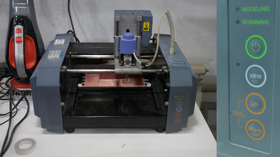
Now that we have places our board let's have a closer look.
It has 3 buttons:
- VIEW
- Z UP
- Z DOWN
The VIEW button allows us to move the milling drill bit along the surface.
We need to make sure that the machine is ready for a new program and not in the middle of a previous program. For this reason we hit it twice.
If we press once, the machine will move to the top right corner of the base.
If we press it a second time, it should move to the bottom left corner of the base.
If it goes to any other position, then the previous program was not finished correctly. The reason is that when we open our pcb design, we set a X and Y position, that indicates where the head will start milling our board. The Modela remembers this point until the pcb has been completed.
When we use the machine, we use the View button to move between the X,Y position we set to mill the board, and the standard home positions to change the mill drill bits.
The Z buttons allow us to:
- change the mill head if we move the Z completely up
- place the drill bit on the pcb surface
CHANGING THE MILL TIP
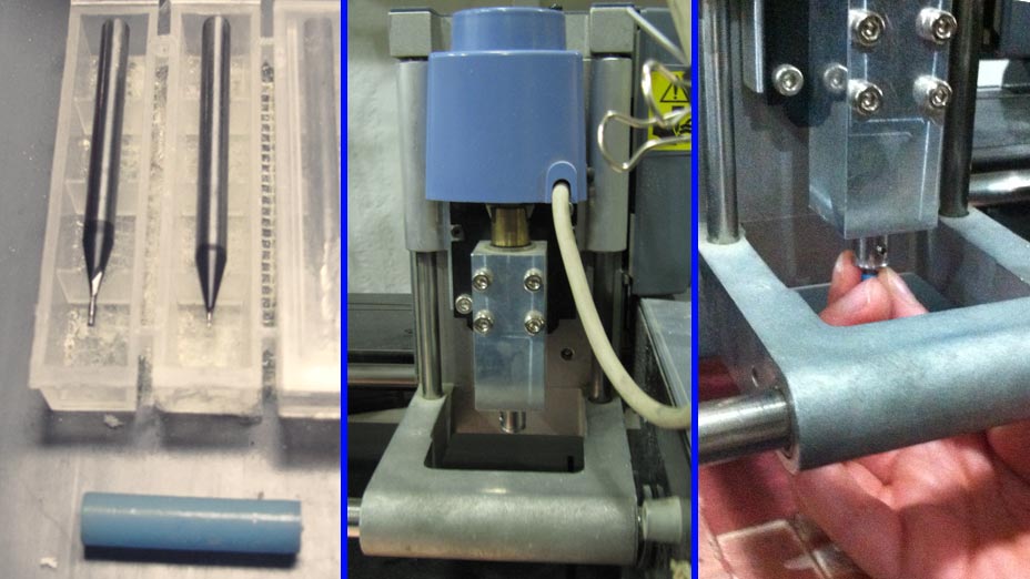
We press View on the machine and we move the head to the bottom left corner of the base.
Then we press Z up till the head reaches the top point.
(This position makes it easier for us to change the drill bit).
To change the drill bit in the machine head we need to first cover the drill bit with a plastic cover to prevent it getting damaged. Then we insert the drill bit in the head, pushing up almost until the end. And we screw it in position (there are 2 holes on the head, we screw in the smalles one).
THE INTERFACE
We use Terminal in Linux to start communication with the Modela, typing:
sudo chmod atrwx/dev/ttySO
and then to open the Fabmodules interface we type:
fab
In the interface we will:
- in: choose png
- process: rml roland
- out: make png rml
A bigger interface will open.
Here we can import our board design, select the preferences and generate the rml file.
01. RECTANGULAR TRACE AT Z=0, 1/64 tip
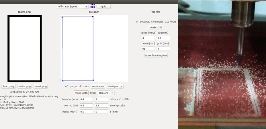
STEPS:
- LOAD PNG and choose our file. (The first file is a rectangle. We use it to check the depth of the mill tip trace on the surface of our pcb.)
- We choose our preferences accordingly to our tip. We are using a 1/64 tip for this job, and we choose the MILL TRACE 1/64 at the top of our inferface.
Since we are only testing the surface, we change a couple of preferences:
OFFSETS: 1
Z (MM) : 0 (because we only want to touch the pcb surface and check the drill bit will trace our rectangle on the pcb with the same depth at every point.
- We then set our XMIN and YMIN to the preferred values. For me it was X=96 and Y=4.
- And MOVE TO XMIN, YMIN
Now we set the Z of our drill bit. We move the head down until we hear a different noise, which indicates that we touched the surface. And then press Z up twice to go back of one step.
- Now we MAKE PATH
- MAKE RML
- Another window will open, where we can select MILL IT
Our machine should now start moving, following the path we generated through the previous steps.
Once the process is finished we press VIEW to have a look at our board.
We press VIEW again if everything is ok to go back to our set X and Y.
02. INTERIOR TRACE AT Z=0, 1/64 tip
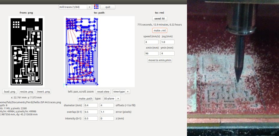
Now we mill the internal trace of our board. Depending on how the previous step turned out, we will need to adjust some values.In my case, since in the previous step, at z=0 the drill bit already got ridd of the copper layer, I will use Z=0 in the new settings too.
STEPS:
- LOAD PNG of internal traces
- reselect MILL TRACE 1/64
- set Z = 0
- (Offset is set at 4 because we will mill around our white trace 4 times, translating of 0.5 each )
- MAKE PATH
- MAKE RML
- MILL IT
Once the process is finished we press VIEW to have a look at our board.
02. RECTANGULAR TRACE FINAL CUT AT Z = 0.5, 1/32 tip
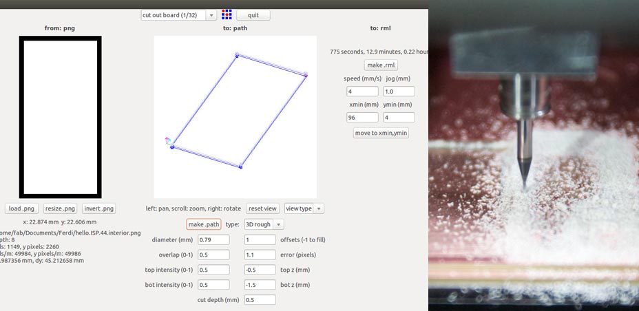
In this final step we will mill our first rectangular file 3 times, getting each time 0.5 mm deeper in the pcb board to cut it!
We will need to use a different drill bit, so we replace the 1/64 with the 1/32.
Hitting the view button we will go back to the bottom left point, where we can easily change the bit.
STEPS:
- LOAD PNG
- select MILL TRACE 1/32
- TOP Z = 0.5
- BOTTOM Z = 1.5
- CUT DEPTH = 0.5
Then we move the new drill bit to our old position:
- MOVE TO X,Y
And we set again the Z trhough the 2 Modela buttons.
Now we can:
- MAKE PATH
- MAKE RML
- MILL IT
When the job is done, we press View again and with a pair of scissors or cutter we remove the milled boards from the sacrificial board. And we clean our board with soap.
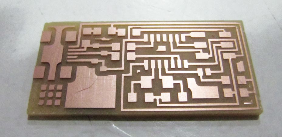
PREPARING FOR THE SOLDERING
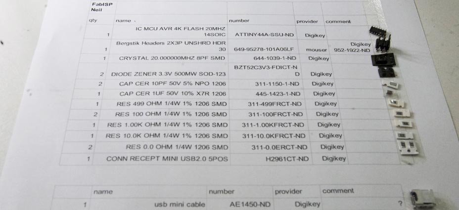
We then look for all our parts. The best thing to do is to print a list of all components needed and put a line of double sided tape on the side, sticking the components onto it. Since they are so small it's the only viable way to remember what is what.
PARTS NEEDED for Neil's FabISP:
1 x ATTINY44A-SSU-ND
1 x Bergstik Headers 2X3P UNSHRD HDR 30
1 x CRYSTAL 20.000000MHZ 8PF SMD
2 x DIODE ZENER 3.3V 500MW SOD-123
2 x CAP CER 10PF 50V 5% NPO 1206
1 x CAP CER 1UF 50V 10% X7R 1206
1 x RES 499 OHM 1/4W 1% 1206 SMD
2 x RES 100 OHM 1/4W 1% 1206 SMD
1 x RES 1.00K OHM 1/4W 1% 1206 SMD
1 x RES 10.0K OHM 1/4W 1% 1206 SMD
2 x RES 0.0 OHM 1/4W 1206 SMD
1 x CONN RECEPT MINI USB2.0 5PO
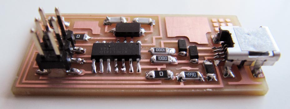
SOLDERING THE BOARD
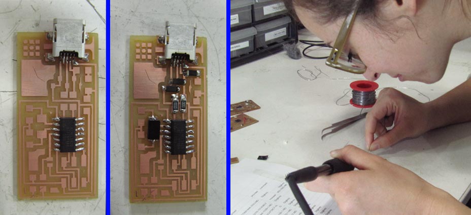
Next we solder the components.
I started from the USB, then the ATTINY.
And all the rest after that.
I kept the pictures provided by Neil as a reference on the side.
TIPS:
- There are components which have a direction: the ATTINY (look for the little circle on one corner of the chip, that's the top left corner= the Diodes (the bar on one side of the diode should be on the right) This picture shows well the parts layout.
- The technique to solder the parts is to first heat with the soldering iron tip one of the copper parts we need to solder to, and melt a bit of solder in that position, and then solder the component on this little blob. THis works like a glue while we solder the other legs of the component.
- While soldering, keep all components in position with tweezers.
PROGRAMMING THE BOARD AND TROUBLESHOOTING
To program the board I followed the instructions in the tutorial.
- I donwloaded and installed Xcode and Crosspack AVR.
- And unzipped the fabISP_mac.0.8.2_firmware.zip from terminal following the tutorial instructions.
- I then programmed the board through terminal. All went smooth up to this point, and when connecting the board to the programmer, led light was green!
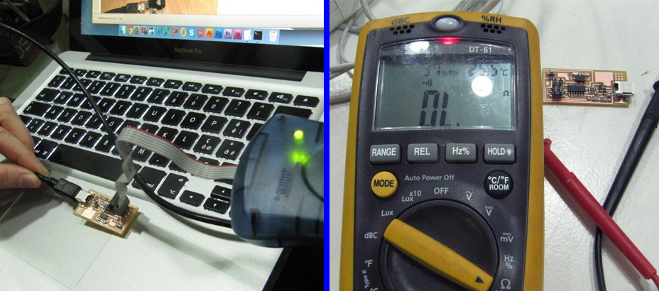
But when looking for the FabISP device on my About Mac > More info > System information > Hardware > USB I couldn't find my device in the HUB list...
Troubleshootin took 2 days of work. I first tried to reprogram the board couple times on both Mac and Linux, using:
sudo make fuse
sudo make program
in case there was a permission error on my computer.
I then checked all connections:
- from USB legs to copper traces
- from USB gnd > to ATTINY gnd > to gnd for connection
- from USB V > to ATTINY vcc > to V for connection
I checked that all my components had the right code, no flipped diodes, no dodgy solder, etc..
I checked under the light tens of times.
When reprogramming the board in Linux, after having programmed it successfully, I unplugged it from the programmer and replugged it into the computer. I then ran:
sudo dmesg -c
to clean the history of connecting/disconnecting devices from the Terminal memory,
then ran dmesg and obtained these errors:
fab@fab-Inspiron-One-19T:~$ dmesg
[269151.297834] ehci-pci 0000:00:1d.7: port 6 reset error -110
[269151.457833] ehci-pci 0000:00:1d.7: port 6 reset error -110
[269151.921840] ehci-pci 0000:00:1d.7: port 6 reset error -110
I looked online for possible solutions but didn't find anything. In the end guess what... It turned out that one of the legs (gnd) of my FabISP was not connected to the copper trace... So for this reason the program was giving me errors. Once resoldered the leg, I plugged it into my Mac and...
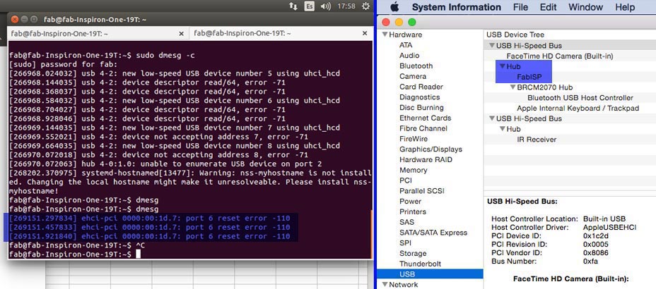
THE FABISP WORKS!!!
What I learnt:
- never trust your soldering
- check with a lot of attention your connections
- don't lose hope
FILES DOWNLOAD LINK
HOME | ABOUT | WORK | CONTACT
Francesca Perona © 2015

This work is licensed under a Creative Commons Attribution-NonCommercial 4.0 International License
Original open source HTML and CSS files
Second HTML and CSS source
Francesca Perona © 2015

This work is licensed under a Creative Commons Attribution-NonCommercial 4.0 International License
Original open source HTML and CSS files
Second HTML and CSS source