Cardboard.
Interesting material.
Not flexible at all.
1. I've always been fascinated by lasercut patterns that can transform rigid into flexible surfaces.
2. I wanted to create a unit which can be both self-contained and modular.
3. I've always been fascinated by kirigamis, and wanted to explore ways of turning a flat sheet in a 3D object.
TESTING
Testing some kerf patterns and understanding which ones allowed better flexibility. I chose to work with the middle kerf because it was the one allowing better flexibility and distributing more evenly on the material stripe the bending stress.
For the locking system I had to test various variables:
- width and thickness of the slot
- margin of the slot from the border of the stripe
- snapping element shape and size (w, h)
- test various engraving lines that facilitate the popping out of the element, since in the plans it can be pushed both upwards and downwards

PROTO BETA
After finding the best fits, I proceded with the design of a circular shape with double rings of snapping elements -one of 6 and one of 8 elements-, and 8 arms.
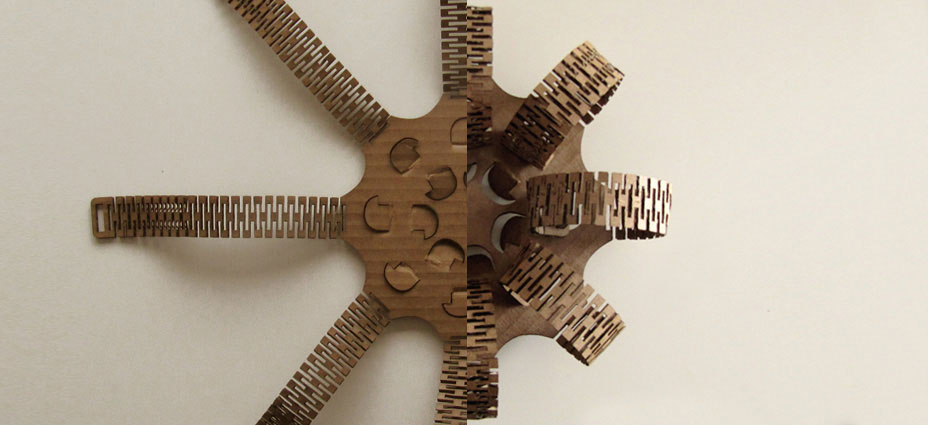
OBSERVATIONS:
- The arms have limited lateral flexibility, therefore the angle of the pattern/arm has to be paraller to the angle of the snapping element. The following prototype corrects this mistake.
PROTO ONE AND MACHINE ERRORS
This design integrated 8 additional longer arms and modified the number and the angle of the snapping elements contained in the 2 rings.
I also added some stiffness to the arm attachments hoping it would help to better handle the flexibility stress on the junction points.
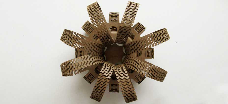
POSITIVE OBSERVATIONS:
- Snapping element works well in both directions
- Number of arms approved
- Distance between inner and outer ring corrected to avoid additional pressure between neighbouring arms
NEGATIVE OBSERVATIONS:
- The rigid elements added stress rather than help to create a smoother, curvier lines
- The laser cutter, although set to 'cut small object first', forgot to cut the slotting line at the end of each arm. Since the laser cutter bed sustained by few metal bars, the floppy arms of the object, once cut from the sheet collapsed, and the laser didn't manage to reach them to cut the final slots.
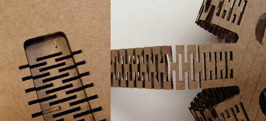
FINAL PRESS-FIT CONSTRUCTION KIT
The final prototype was lasercut laying on a MDF bed. The power of the laser had to be adjusted few times (much higher than the suggested: 120 vs 90) to produce a neat cut on the MDF bed. Cutting on this layer also produced a lot of smoke that affumicated the bottom part of the prototype.
MEASURES:
The prototype is around 50x50 cm.
The arms are 10 and 15 cm.
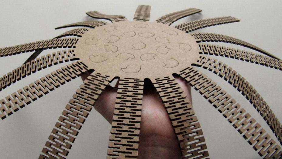
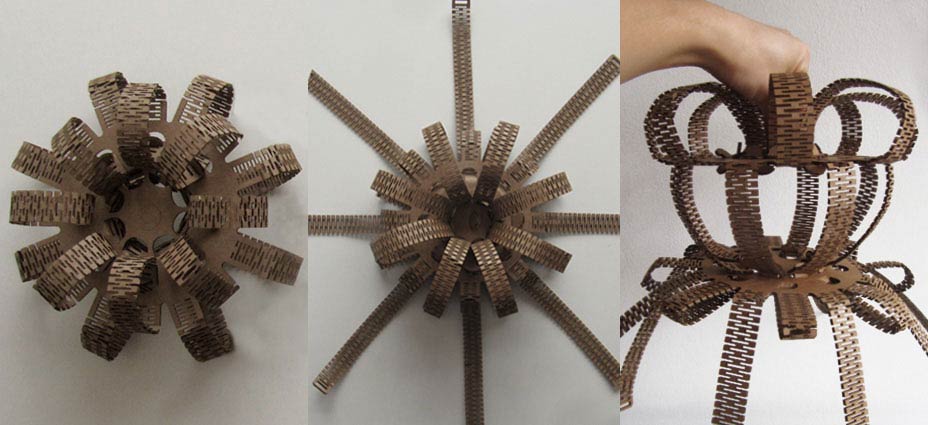
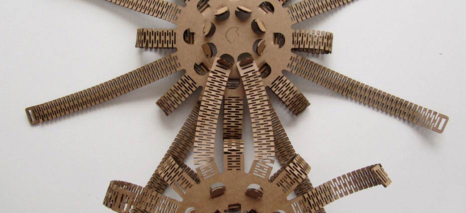
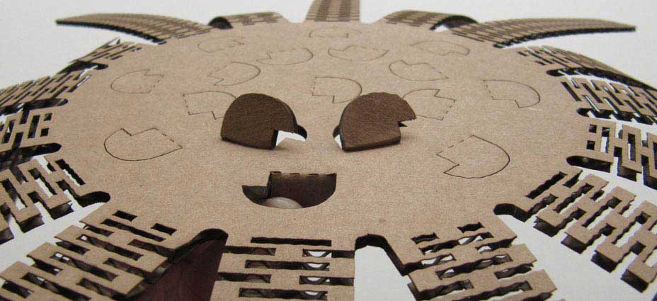 The final object can work as a self-contained pressfit with multiple possibilities of arm snaps on the top and the bottom. But the arms can also be snapped to contiguous objects on the side and piled onto other objects.
PARAMETRIC DESIGN
The model was produced in Rhino and later made parametric for future development. Timewise, I preferred to invest in creating a functioning object first and then attempting the parametric design, since my experience in parametric programs is limited and the need for testing was immediate.
Grasshopper sketch will be posted shortly!
FILES DOWNLOAD LINK
Interesting material.
Not flexible at all.
1. I've always been fascinated by lasercut patterns that can transform rigid into flexible surfaces.
2. I wanted to create a unit which can be both self-contained and modular.
3. I've always been fascinated by kirigamis, and wanted to explore ways of turning a flat sheet in a 3D object.
TESTING
Testing some kerf patterns and understanding which ones allowed better flexibility. I chose to work with the middle kerf because it was the one allowing better flexibility and distributing more evenly on the material stripe the bending stress.
For the locking system I had to test various variables:
- width and thickness of the slot
- margin of the slot from the border of the stripe
- snapping element shape and size (w, h)
- test various engraving lines that facilitate the popping out of the element, since in the plans it can be pushed both upwards and downwards

PROTO BETA
After finding the best fits, I proceded with the design of a circular shape with double rings of snapping elements -one of 6 and one of 8 elements-, and 8 arms.

OBSERVATIONS:
- The arms have limited lateral flexibility, therefore the angle of the pattern/arm has to be paraller to the angle of the snapping element. The following prototype corrects this mistake.
PROTO ONE AND MACHINE ERRORS
This design integrated 8 additional longer arms and modified the number and the angle of the snapping elements contained in the 2 rings.
I also added some stiffness to the arm attachments hoping it would help to better handle the flexibility stress on the junction points.

POSITIVE OBSERVATIONS:
- Snapping element works well in both directions
- Number of arms approved
- Distance between inner and outer ring corrected to avoid additional pressure between neighbouring arms
NEGATIVE OBSERVATIONS:
- The rigid elements added stress rather than help to create a smoother, curvier lines
- The laser cutter, although set to 'cut small object first', forgot to cut the slotting line at the end of each arm. Since the laser cutter bed sustained by few metal bars, the floppy arms of the object, once cut from the sheet collapsed, and the laser didn't manage to reach them to cut the final slots.

FINAL PRESS-FIT CONSTRUCTION KIT
The final prototype was lasercut laying on a MDF bed. The power of the laser had to be adjusted few times (much higher than the suggested: 120 vs 90) to produce a neat cut on the MDF bed. Cutting on this layer also produced a lot of smoke that affumicated the bottom part of the prototype.
MEASURES:
The prototype is around 50x50 cm.
The arms are 10 and 15 cm.

 The final object can work as a self-contained pressfit with multiple possibilities of arm snaps on the top and the bottom. But the arms can also be snapped to contiguous objects on the side and piled onto other objects.


PARAMETRIC DESIGN
The model was produced in Rhino and later made parametric for future development. Timewise, I preferred to invest in creating a functioning object first and then attempting the parametric design, since my experience in parametric programs is limited and the need for testing was immediate.
Grasshopper sketch will be posted shortly!
FILES DOWNLOAD LINK
HOME | ABOUT | WORK | CONTACT
Francesca Perona © 2015

This work is licensed under a Creative Commons Attribution-NonCommercial 4.0 International License
Original open source HTML and CSS files
Second HTML and CSS source
Francesca Perona © 2015

This work is licensed under a Creative Commons Attribution-NonCommercial 4.0 International License
Original open source HTML and CSS files
Second HTML and CSS source