Development
I start the development of my final project in the second week of Fabacademy creating a 3D project. I start using 123D Design but after some week I begin to work with solidworks so I want to do the 3d sketch again because Solidworks is much powerful.

In week 6 and week 7 I start using eagle to create circuit board and learn the tecnique to create an electronic board. Unfortunately my first experiment goes bad, but I'm working to resolve my problem. I want to try to mill and solder my Arduino Uno board and my Motor Shield.
Looking on google I found that in 2013 The Fab Academy at AS220 Labs has developed a version of drawbot following the project Makelangelo 2 and using the adafruit motor shield.
In parallel I found several good projects from which I can take inspiration. In particular, I saw that the community has worked hard on the software and that currently the best two software / firmware for this kind of robot are:
Makelangelo
Polargraph
The second project seems much broader and I think it will be my choice to start the test. It has many tools and many kind of strange pattern that I can use to reproduce my image files.
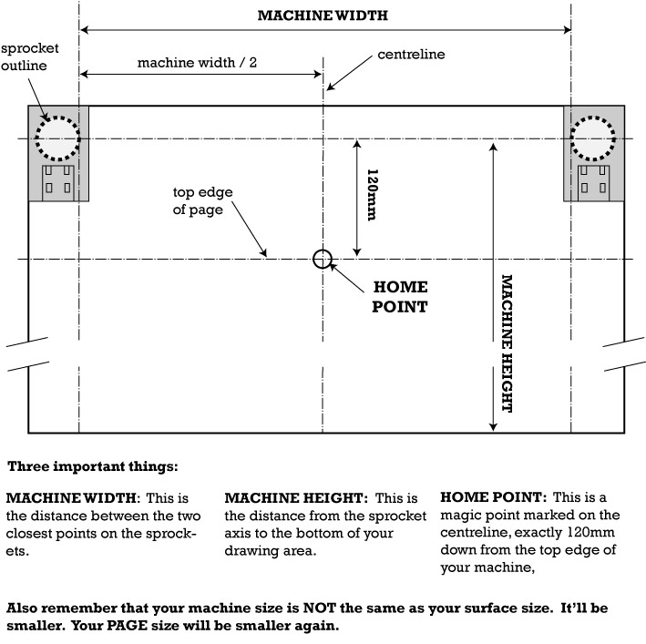
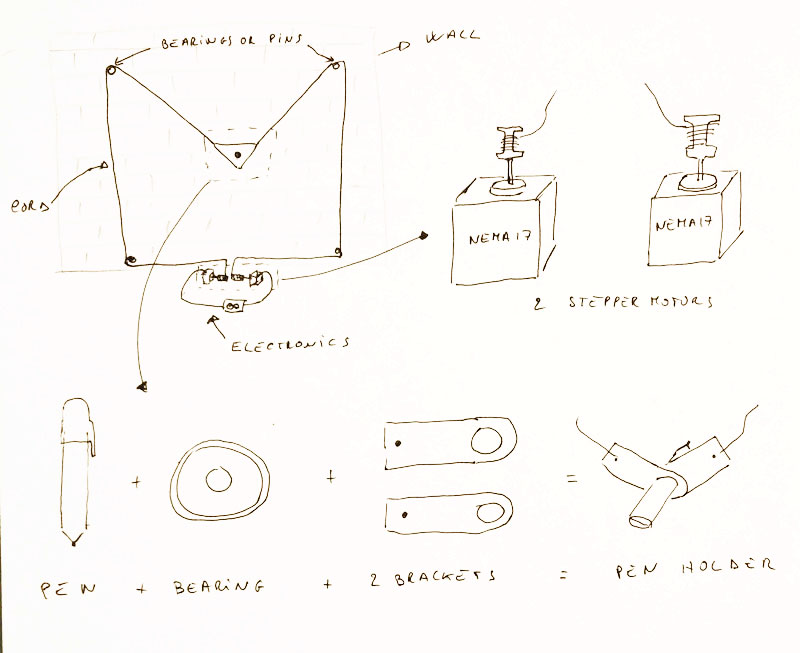
What I have learned is that is very important to measure right all the component to have a good work. Below a diagram of the most relevant measure to take.
To proceed to the design of my version of drawbot I'll need the following components:
- one arduino board(arduino uno is enough so I think to use an ATMega328 ) - from Digikey - approx. $4
- two bipolar stepper motor - from ReprapWorld - approx. $22 | from an old printer approx. $0
- one servo motor - from ReprapWorld - Approx. $5
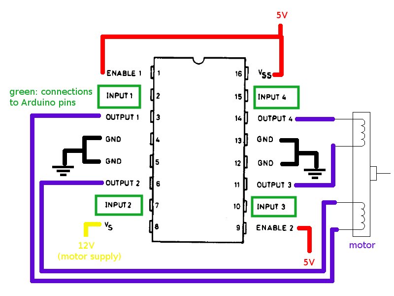
- two stepper driver (L293D) - from Digikey - approx. $6 - PN: 497-2936-5-ND
OR one Adafruit motor shield - from Adafruit - approx. $20 (in the beginning I used this one)
- capacitors - from Digikey - approx. $3
- resistors - from Digikey - approx. $1
- resonator - from Digikey - approx. $4
- wires - from Digikey - approx. $1
- two pulleys - 3d printed part - approx. $0.1
- two fishing lines - approx $1
- three bearings - from ReprapWorld - approx. $1 (at the end I don't need anymore)
- a bit of wood - from FabLab - approx. $1
- many sheets of paper - local stationery shop - approx. $2
- two 10m flexometer - local ironmongery - approx. $5 (it works also without it)
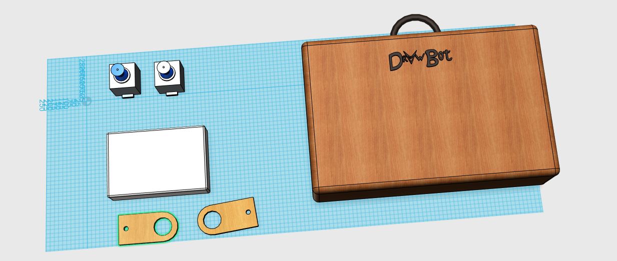
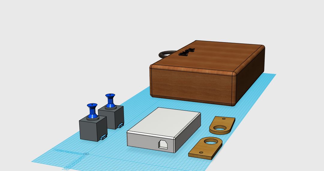
My goal is to fabricate all the components that I will need, so I want to design my arduino board and my motor shield, modify the original Polargraph or Makelangelo firmware, design my gondola, my electronic holder box and the stepper motor holder. Moreover, I want to create a case to transport my drawbot.
Below attached some of the first sketch of my project.
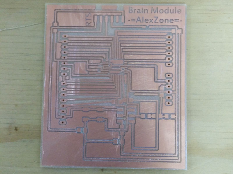
Regarding Arduino, I'm already working on board and now I designed this one.
I designed everything with Eagle and then machined and welded. The same process will use it also for the motors shield which will start to design soon (I will develop for the output devices assignment).
For the case and the stepper holder, I will model in rhinoceros and I will export DXF turning them into a press-fit and then I will lasercut.
To make the gondola (the arm that hold the pen) I will make the three-dimensional model and I'll 3d print it.
For the pulleys I will design it and I will print in 3d to make a test. If friction is not enough I will buy some metal pulley.
Currently I'm a bit late with the construction, because of the many work engagements of this period. Until now I managed to make the Arduino and to start studying the motor shield. I had a look at the firmware and software and made a first prototype using commercial components. What I do miss are mainly mechanical drawings, part of the electronic and to test and modify the firmware.
Right now I have no questions to do because I do not know what to expect in the next steps. For sure I need some advices on electronics and mechanics to make my drawbot as possible accurate and scalable.
In my schedule next steps are:
- Finish and test the electronics
- Modify and test the firmware
- Make the 3d model of all the parts
- Prototype all parts
- Test the machine
After all I try to improve all and finish my work.
UPDATE 26/05/2015
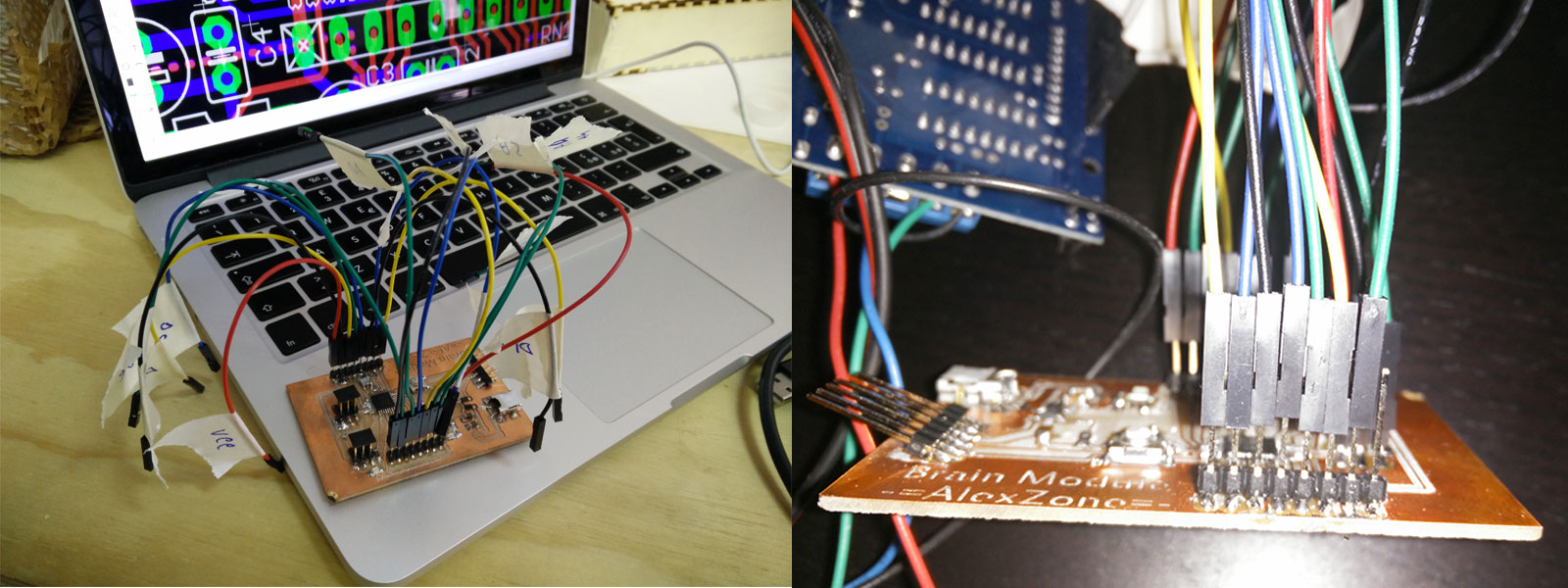
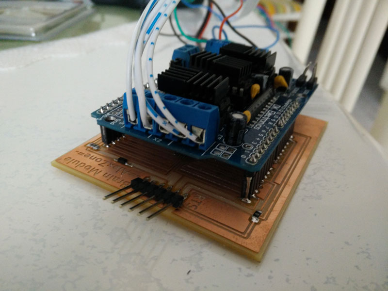
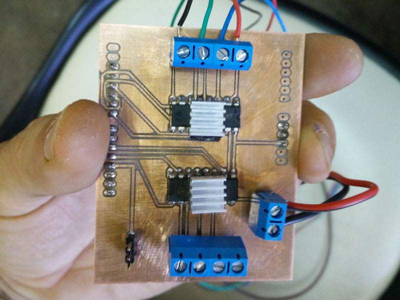
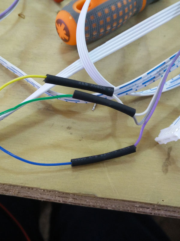
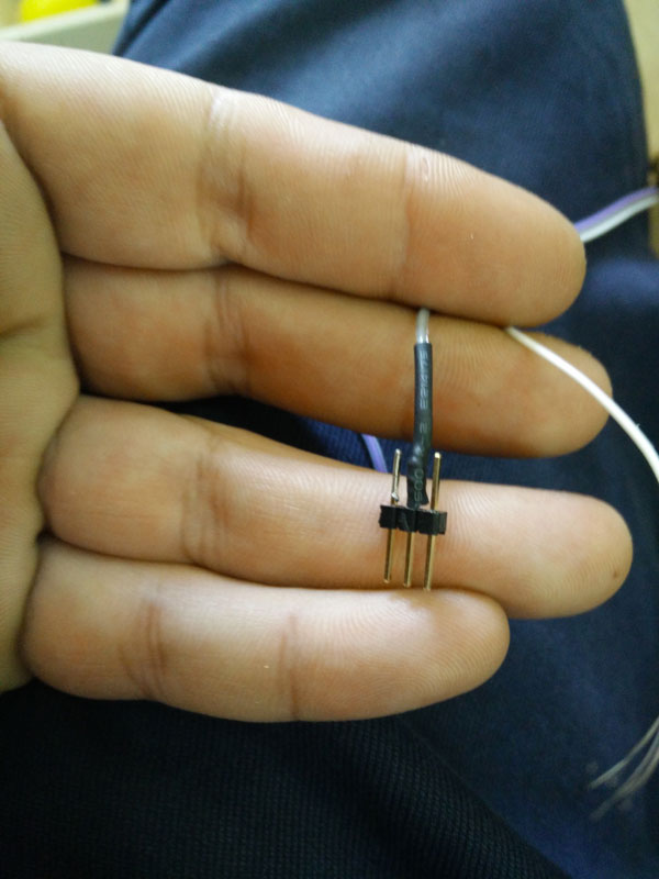
I've made some tests with my first arduino protopype and an Adafruit Motor shield.
Actually my board haven't the standard pinout so I have to connect it to the motor shield in this way:
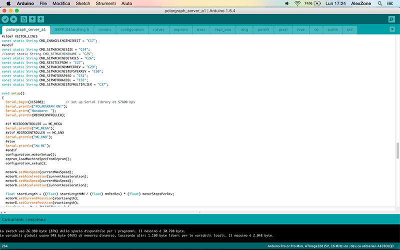
After I uploaded the polargraph firmware to my brain module (it's my arduino name) but soon I discover that it can't connect to the Polargraph Controller application. So I begin to look into the code to discover what is the problem.
I found that to communicate to the serial port, the firmware is set to 57600 bps. So I try to use the arduino serial monitor to see the echo af the board and I see that it print strange characters. I remember the same problem with some 3dprintes. So I decide to change this value. After some attempts I set the value to 115200, compile the firmware and my serial monitor seems not work again. But after I change the baud rate of the serial monitor to 57600bps all works fine. So the final vale are 115200 into the firmaware and 57600 into the serial monitor.
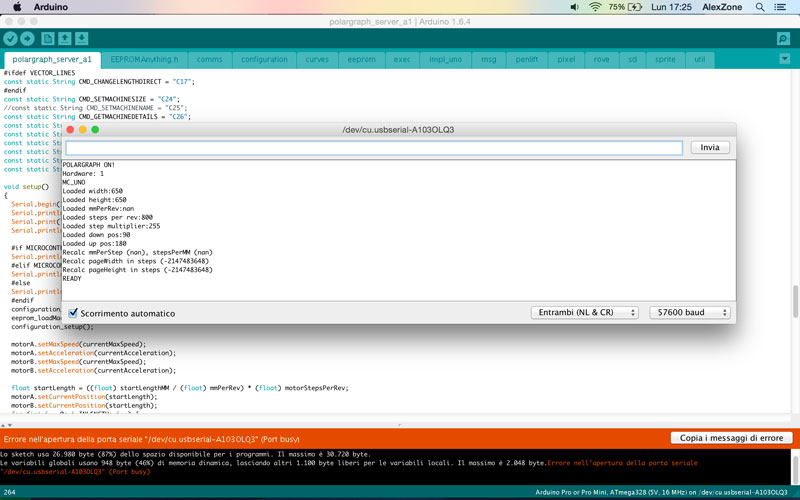
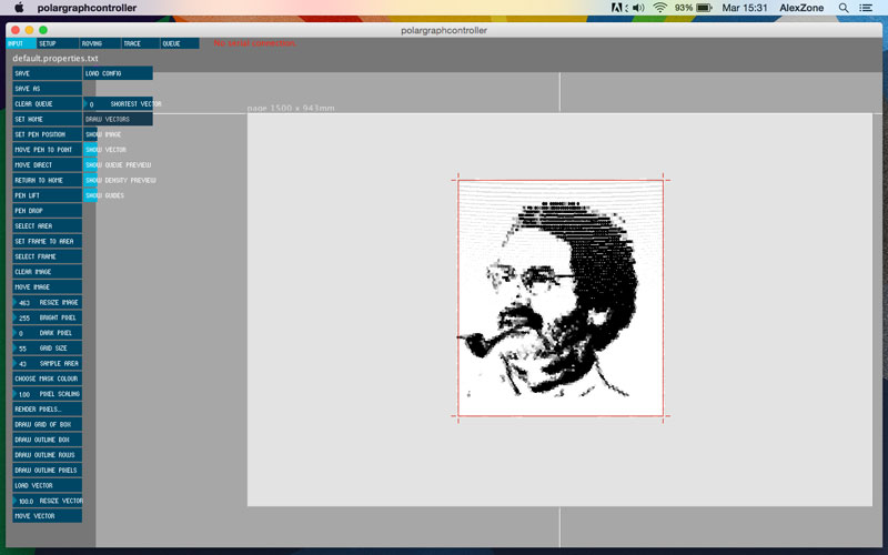
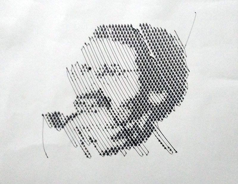
Now I can connect to the Polargraph without problem. Now it's time to study the software. Polargraph is very powerful but it is very complex the fisrt time. I took several days to learn how to setup how make my fist correct code. This is one the last test I've made.
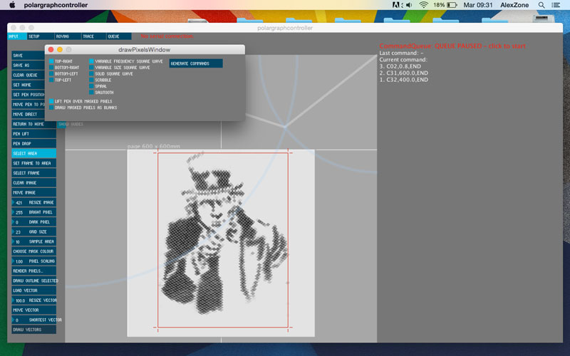
I connect two nema 17 to my board and decide to use external power for the shield. I found a modem power adapter (5v 2A) that seems to be perfect for my project (it has olso a barrel connector, the same that use the Arduino board.). Now I can test my board and my software and all seems to be ok.
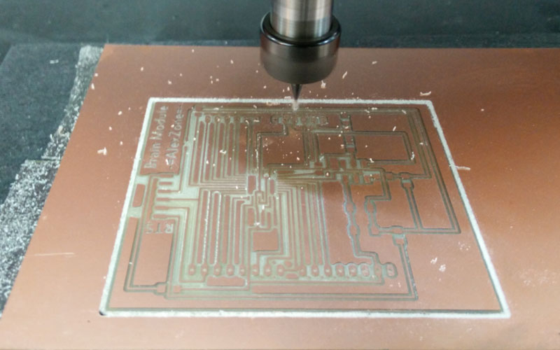
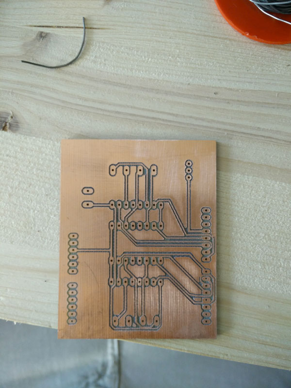
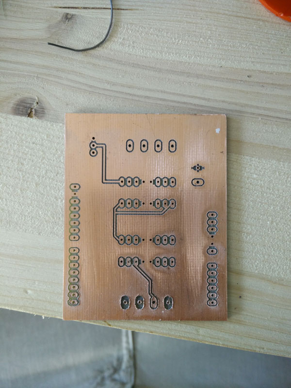
Next step for my project is to design a new board with the original pin connection of the arduino uno, so I can put my shield without trouble. So I began to work in Eagle and today I finish to mill it.
Next steps are:
- solder my board e finish it
- design the box and the case
- work on the way to rewind the wires which drive the pen. For now I'm thinking to the same method used by the flexometer.
UPDATE 31/05/2015
I finish my new arduino but I two big trouble: first of all I use 20MhZ resonator and Arduino Uno out of the box has only 8Mhz or 16Mhz clock. I try in many way to make it working and after a day of work I reach to have it working uploading firmwares using FabISP and to work with the right timing and the right baudrate.
To do that I download the old version of Arduino (1.0.5) that seems to work well with modified doard. I dowload this compiled bootloader and I put into the Arduino folder. In OsX right click on the Arduino app > Show Package Contents, navigate into Contents > Resources > Java > hardware > arduino > bootloaders > atmega and put the hex file on it. Now navigate back and open board.txt, and add this text at the end:
##############################################################


atmega328p20.name=ATmega328P, 5V, 20MHz external ceramic resonator

atmega328p20.upload.protocol=arduino

atmega328p20.upload.maximum_size=30720

atmega328p20.upload.speed=57600

atmega328p20.bootloader.low_fuses=0x96

atmega328p20.bootloader.high_fuses=0xDA

atmega328p20.bootloader.extended_fuses=0x07

atmega328p20.bootloader.path=arduino:atmega

atmega328p20.bootloader.file=ATmegaBOOT_168_atmega328_pro_20MHz.hex

atmega328p20.bootloader.unlock_bits=0x3F

atmega328p20.bootloader.lock_bits=0x0F

atmega328p20.build.mcu=atmega328p

atmega328p20.build.f_cpu=20000000L

atmega328p20.build.core=arduino:arduino

atmega328p20.build.variant=arduino:standard

##############################################################
Now, starting Arduino IDE, I can find my new board and I can burn the bootloader with the right parameters.
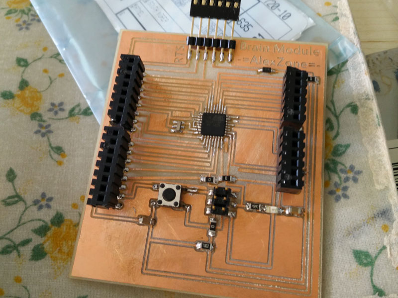
The second trouble was that if I use the board with led, buttons, or other test circuits, everithing goes well. When I put my motor shield I can't use it. The first thought I had was that did not work the resonator again, so I decided to change it with a 16Mhz and test the board again. But nothing change. So I focus on the shield. I download the eagle board from adafruit site and after studing it I discover the it uses the miso and mosi pin to connect the the 74HC595. It is a 8-pin shift register, in other words you can use it to control 8 outputs at a time while only taking up a few pins on your microcontroller. In my board I not connect these pins beacuse I use it for the Fab-ISP connection and I thought they not serve to controll the motors. Moral of the story I have to redraw my arduino angain but...how many things I learned!
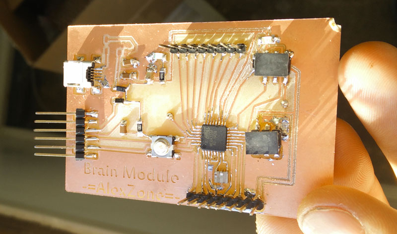
This will be my final 328p brain module.
To make the project scalable I want to put all the electronic and the motor to the ground so only the line and the pen is on the wall.
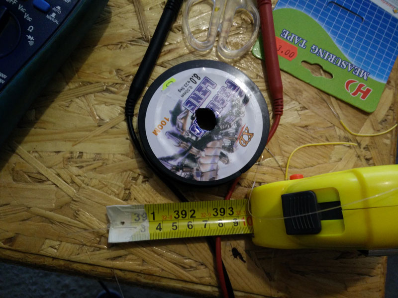
The big problem with the drawbot is that the movement is also calculate with the pulley diameter. But if I have only a pulley were put the line, and I have a long line, the pulley diameter going change.
To solve this problem I want to use an hacked flexometer to rewind the line. So around my pulley connected to the steppers, I just roll up the line four or five times, just to have the right friction and at the end, the line can rewind or comes out. In this way the pulley diameter is always the same and on the other side, the pen can move without problem.
Moreover in order to not twist the line on the pulley, I want to put some guides.
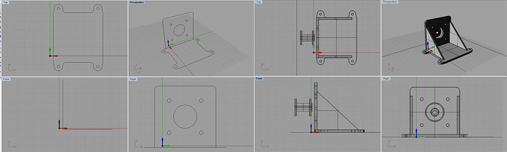
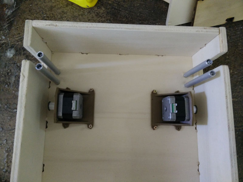
In parallel I begin to design my case where I want to put all the elecronics, the motors and the hached fleximeters. I start with Rhino and I begin with the motor pulley and go on with the motor support and the box.
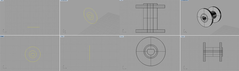
This is the Rhino file
UPDATE 09/06/2015
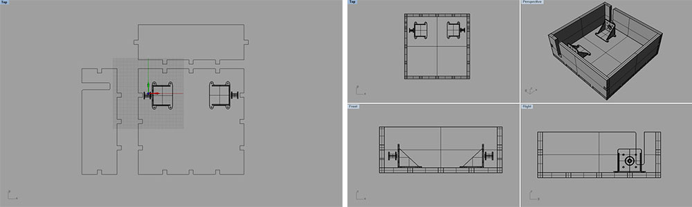
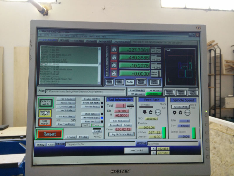
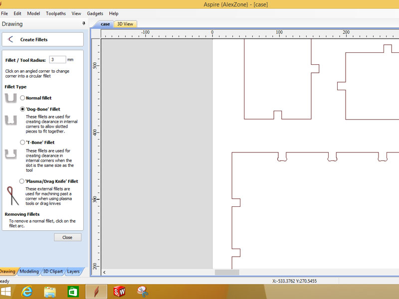
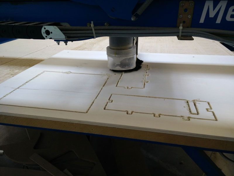
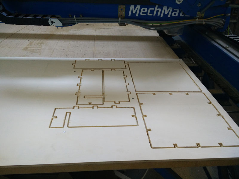
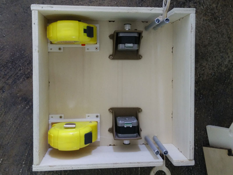
This is the summary of the last week. First of all I mill my case. So starting from my rhino file I export in dxf and I go to Aspire. Initially I want to laser cut the case but in our fablab we have some problems with the machine when cuts. So I prefer to mill it! To do that I have to add some dog bones and t-bones for the joints. Moreover I have to add some tabs to hold the wood when I mill each part. The first cut goes bad, because I do an error selecting the cut over the vector. After I export the gcodes egain selecting to stay outside the vector. Finally I have my case and I can start assembling it.
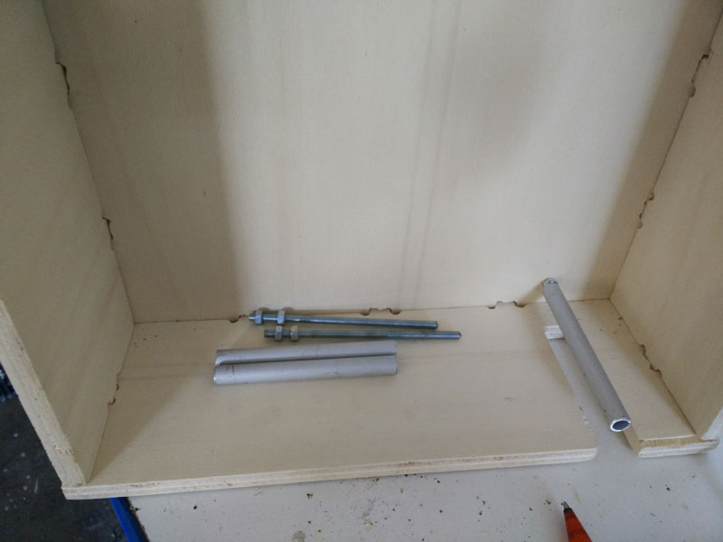
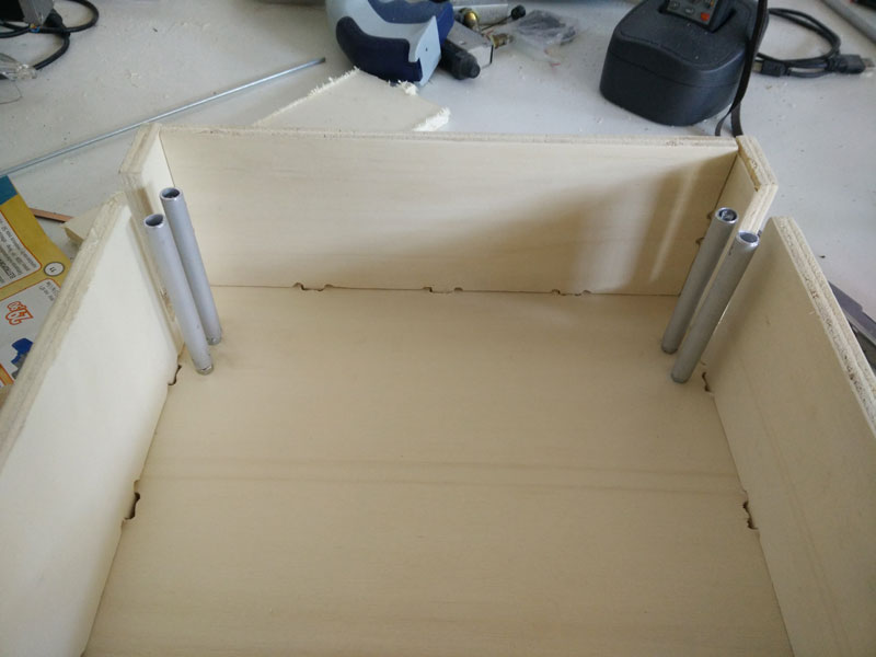
Now I have to create my home made bushes where I want to put my line. To do that I cut a threaded rod m5 and some pieces of aluminum tubes and with some nuts I block into the wood.
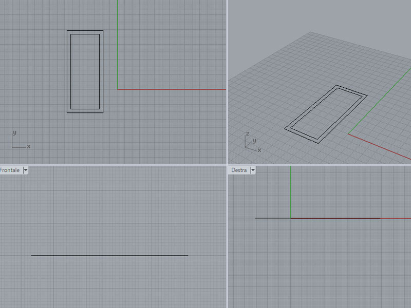
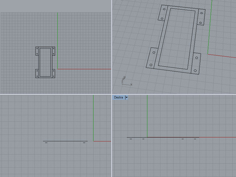
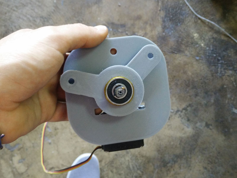
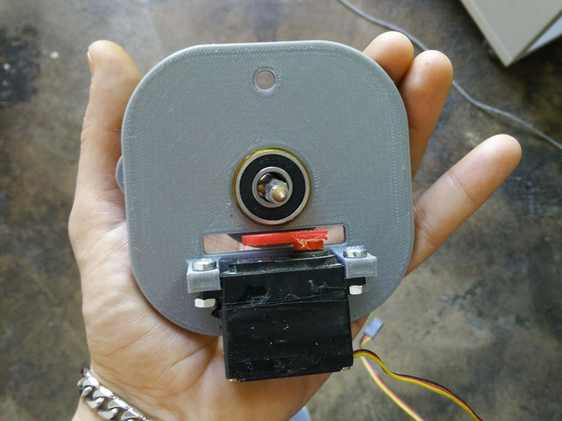
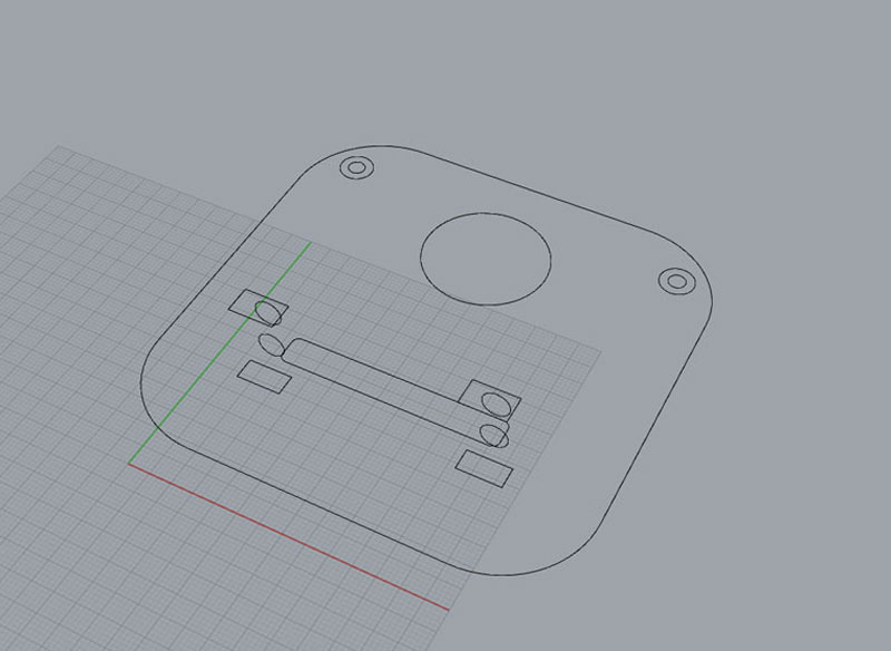
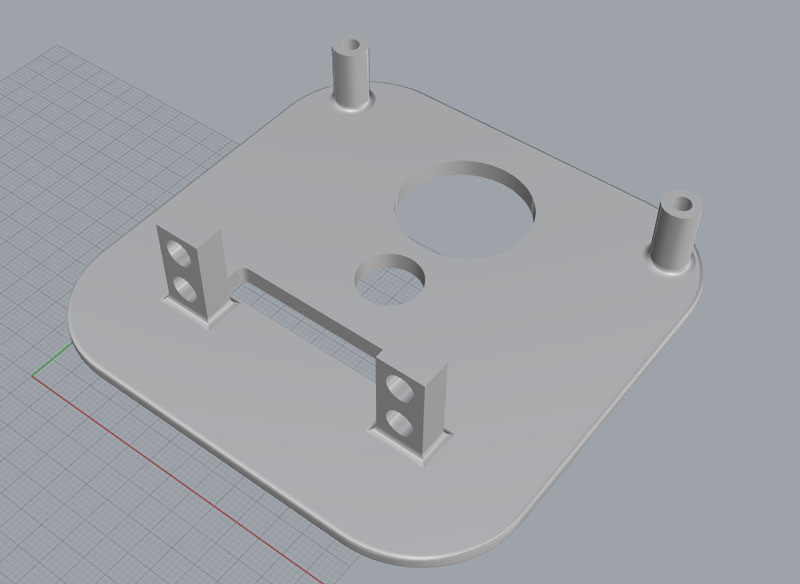
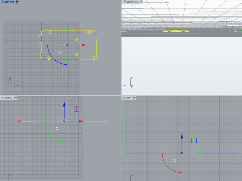
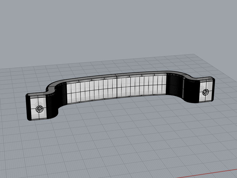
Next step I begin to design my gondola, my motor holder and my flexometer holder. I use Rhino and as usual I start from the 2d sketch and the create the solid. For the gondola I want to use some bearings to make the pen movement smooth.
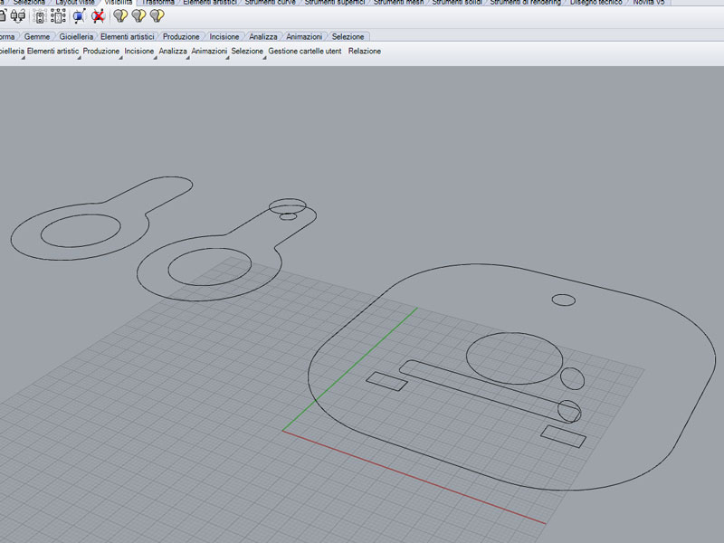
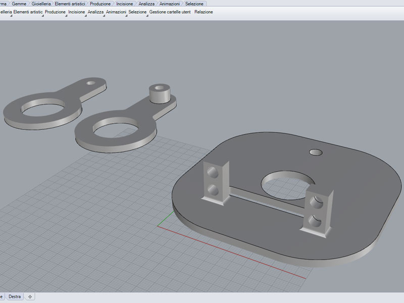
This is my Rhino file.
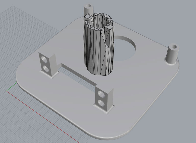
The same with the flexometer holder:
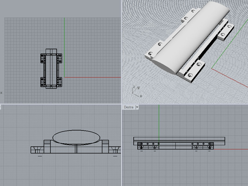
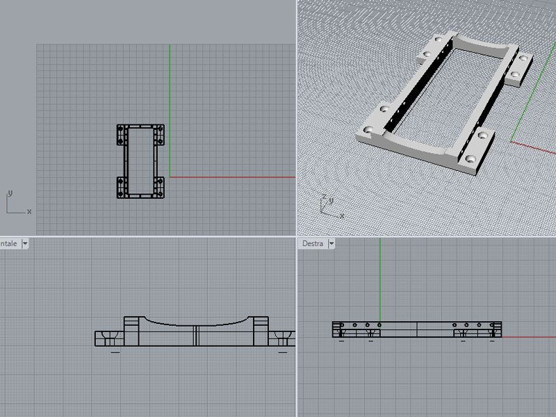
This is my Rhino file.
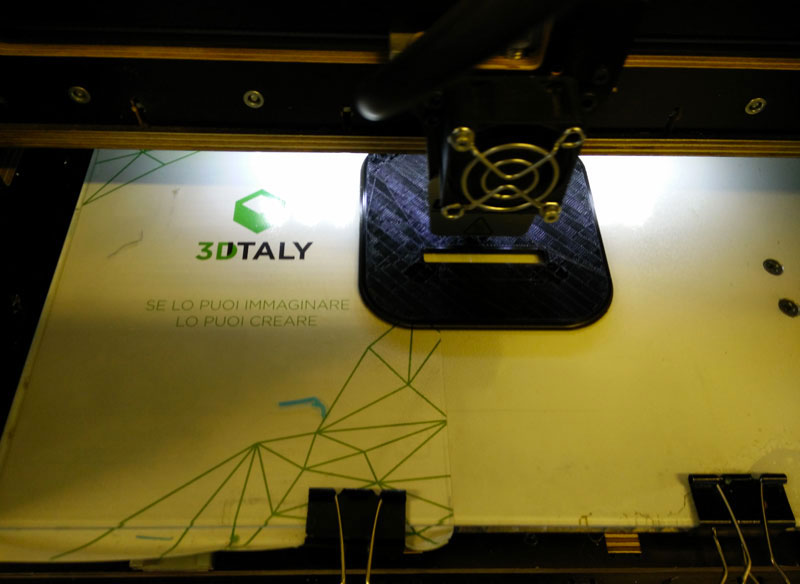
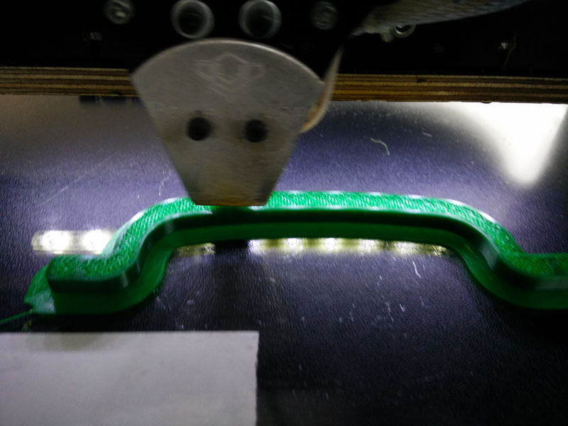
Now it's time to print it. I use the Wasp delta and do the gcode with cura setting 40% as infill and 1.2mm of shell thickness because I want it strong. Now I can go ahead assembling my box and my pulley.
I have to finish my last arduino. As usually I have to mill and to solder it. This time I feel lucky
This is my eagle 328p brain module files.
After smoke test and burning bootloader all seems to be ok so I can begin to test my drawbot.
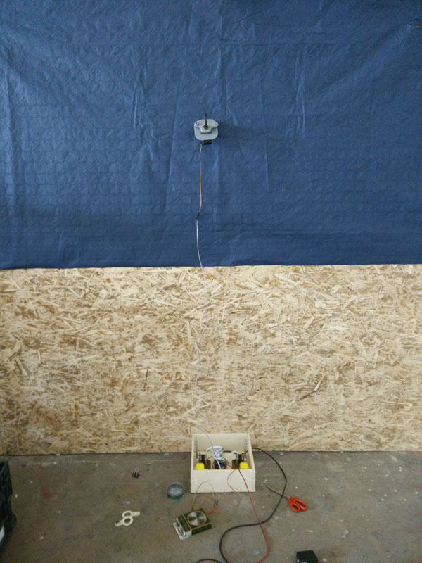
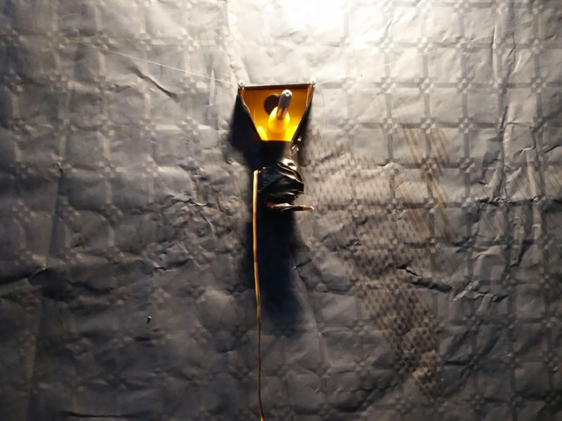
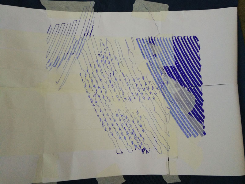
First of all I take a wall and I measure the dimensions and put 4 pins at the corners because here I put the line. After I find the center and the hom point (12cm below the top center of the wall. Then I put a paper on it (I only found a blue big paper, is not the best but for now is good). Using the adafruit motor shield I upload the firmware and start the first tests.
It is not simple to understand what is going wrong but after a while the motor driver became very very hot and stps working. Now I'm using a 12v 1A dc adapter and I ave also two sinks on each motor. I try different dc adapter: 5V 2.5A, 12V 1A, 12V 2A, 9V 1A and if I go under 12V my motor seems not moving well, if I use more than 1A the drivers became terrible hot after few minutes. Moreover the sound of the motor is very horrible.
I think is my fault with the arduino, so I try with an original arduino uno but I discover that the problem is the same.
This is one of the early tests with the 12V 1A dc adapter and my arduino:
Ok go ahead and start thinking at the motor shield. I want to create my own and I want to use the L293 H bridge that is the same driver motor that use the first adafruit motor shield.
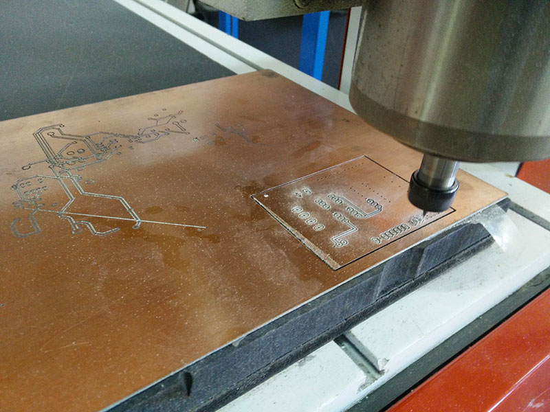
I read the datasheet and begin to design my board in Eagle. I have a lot of pin to connect and I discover that it is impossible to use one single face board. I decide to mill double face (fear for this). To do that I design 2 holes on my board that I use to have two important point for the rotation of the circuit. First I drill it, after I cut the board border, the drill the pin holes and after do the pocket. Now I detach the board milled from the milling machine and using the holes and the border of the cut I rotate my board. In aspire I do a vertical mirroring of the B sides of the board and then start the other pocket.
After this is the result:
This zip contains all my board files (eagle, aspire, vectors and gcodes).
Seems ok then I can start solder all the components. I finish and start with the multimeter to check all the connection and I see that I have a shot circuit on the board. Looking with a lens and a led light I discover the problem but it is under an L293d so it is impossible to remove. Moreover I soldered pins on the wrong side so I can't put my shield on my Arduino.
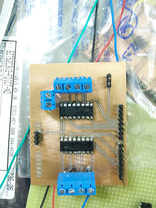
Angry about that, I do a breath and I get back on the milling machine to make a new board.
This time I check all more carefully and then begin to solder and the result was very good.
Now it's time to test it. Magically it works perfect. I'm very happy for this because my knowledge of electronics are zero and all my work comes from the fabacademy lessons so I am very proud of me!
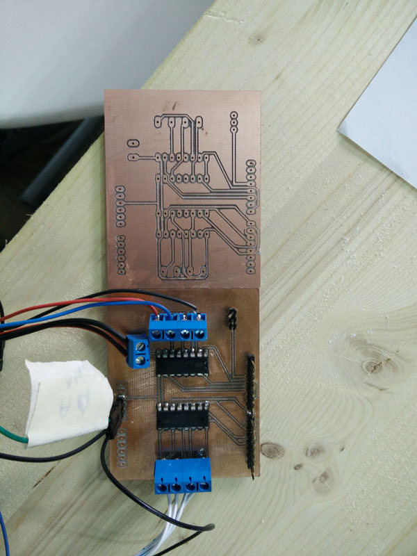
Come back to the drawbot and make more tests with new electronic.
To make it working I have to modify the polargraph firmware. Using the same chip of adafruit I think that it is possible to do. Some days ago I started studying the adafruit libraries and the arduino code of polargraph. Is quite difficult for me to understand all but internet help me to find material where study. After days of tests I found the key: (on the right the original version and on the left my mods)
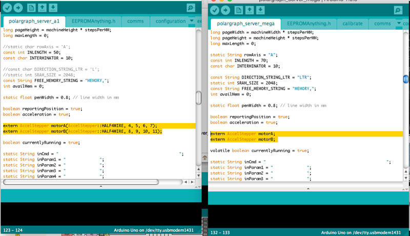
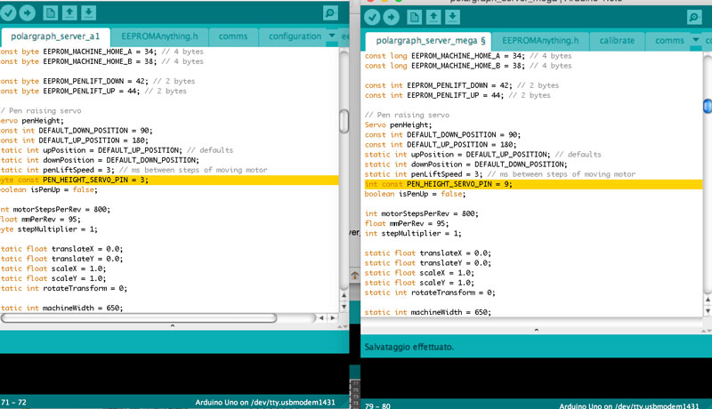
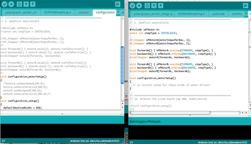
This zip contains my modified version of polargraph fw for arduino uno.
Now I can do the real test on my drawbot. The noise of the motor is the same but the drivers is less hot.
After some fine setup on the pulley diameter and the paper dimension in polarghaph I notice that the line when the pulley move, it stretch and don't move well. So I think that the problem is the weight of the gondola and of the bearings. To do a test a download a gondola from thingiverse, print it and test my machine again. BINGO! Found the problem! Now with a lighter gondola my machine works better and the results seems quite good.
Moreover one of the problem is the pen that can't write in vertical. I buy differents kind of pens adn at the end I decide to use THIS ONE.
Casually the gondola I downloaded is design to hold that pen! So I decide to design my own but I want to keep the pen holder.
Now the problem I have to solve remain the noise on the motors. I search on internet and I found the can be a problem with the unfiltered power supply. I try to use regulated output of the original arduino to give the power. to do that I have to modify my shield to get the Vin from the Arduino and not from an external power. Moreover I read that with the Arduino mega 2560 the polargraph firmware is more powerful. So I modified the firmware again to use with the arduino mega (LINK TO FILES).
Starting with new test the sound is very good and the motor movements are very very smooth and the drivers are less hot. Seems a good solution. So I decided to create my electronic holder for the arduino mega.
I download from internet the design of the arduino mega and use it to create my holder. I decided also to put a fan to cool the electronics.
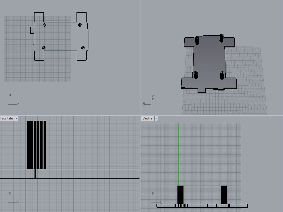
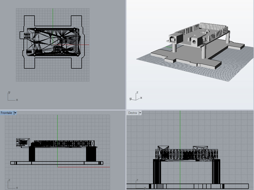
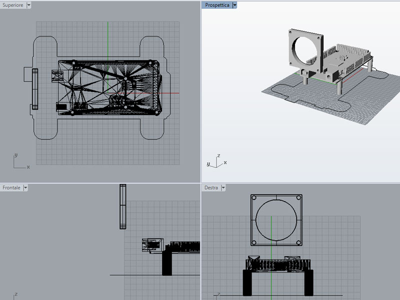
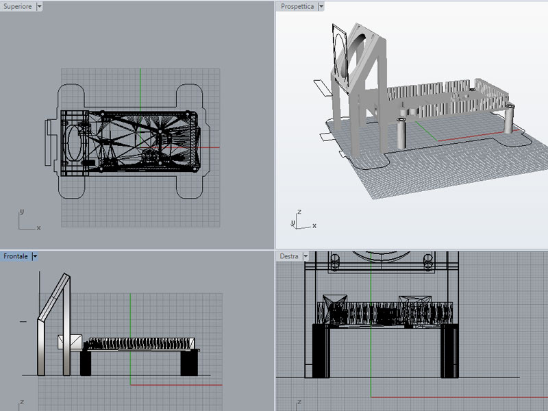
LINK TO RHINO FILE
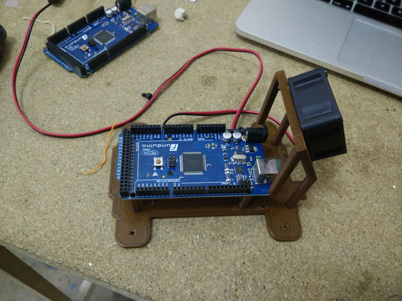
As fan I use a little one and I connect to the same connector of the motor power.
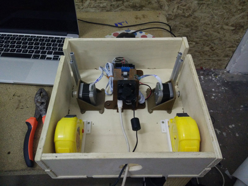
I can finish to mount my box with this last piece and the result is pretty good.
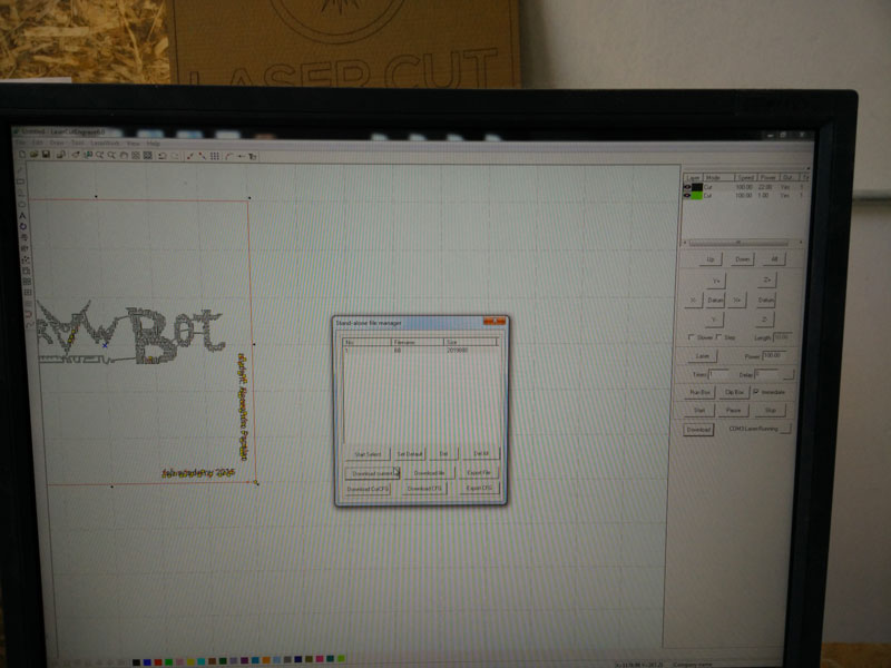
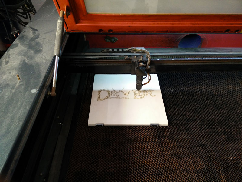
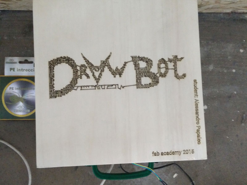
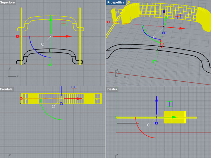
 In the same time I design an handle for my box and finish my vector graphic that I want to lasercut on the top and on the inside of the box. I use a hinge to attach the lid of the box.
LINK TO RHINO FILE
LINK TO SVG FILE
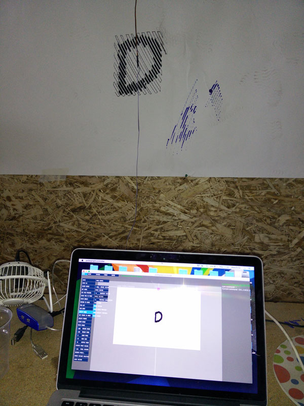
Now I can focus only at the drawbot mechanical. I start with many test and each time I adjust some parameters or modify the pin position on the wall. The results comes one..
PS: I have to create my cable for the servo..I don't have a long wire for it so I make it.
After that I optimize more and more my machine and study the software that is very very big.
Meanwhile, I am preparing a surprise to Neil ..
And this is the final result
CONCLUSIONS:
My project seems to work very well, with my version everyboby can make a drawbot with less than $50, but if you retrive the motors of the old dot matrix printers you will be able to spend less than $30.
At the end the only thing that not works properly is the power supply for the motors which forces me to use the power filtered by Arduino. I think that someone with a good electronical skill can help me because it will certainly be an easy problem to solve. The other thing I'm thinking about it is the use or not of tape measures that give me more precision but it increase the cost of the project and probably are not as important. What works good is the arduino "brain module" and the motor shield. Also the gondola works like a charm.
So, what I'm learned? A lot of things. How to 2d/3d design a project, how to develop it, how to design an electronic board, how to control it with a graphic interface, how to program it, how to control motors in speed, acceleration and movements, how to works with differents baudrates, know and solve mechanical problems related to materials and friction, etc.