measure something
One_week_long Steeplechase
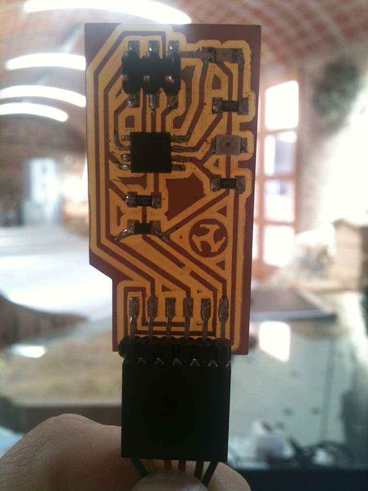
#1_Designing a (attiny 45) Light.me board
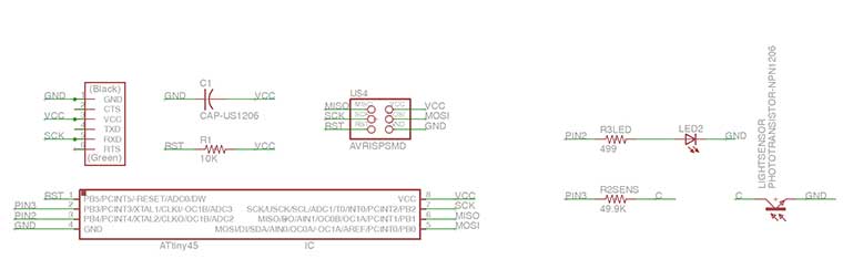
I choose to make a version of the Neil's Hello light board plus an a LED, in order to control the Fading function inversely proportional to the environmental light.
After several attempt, including one board not giving back any feedback, and one not receiving data from the sensor due to a not “consistence” issue between schematic and board in Eagle, I found the design that seems to be the correct one
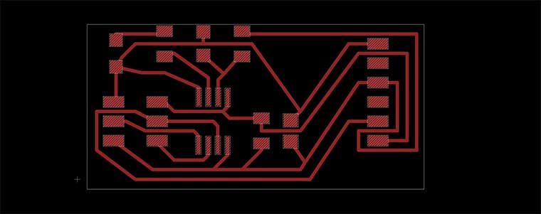
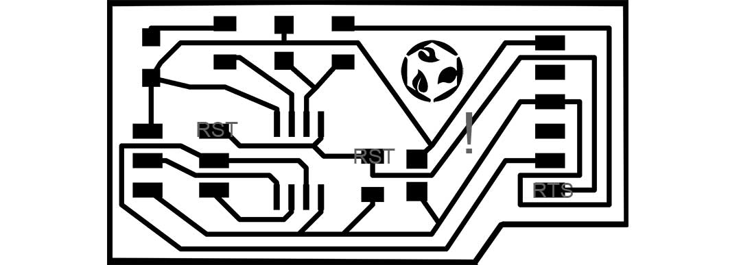
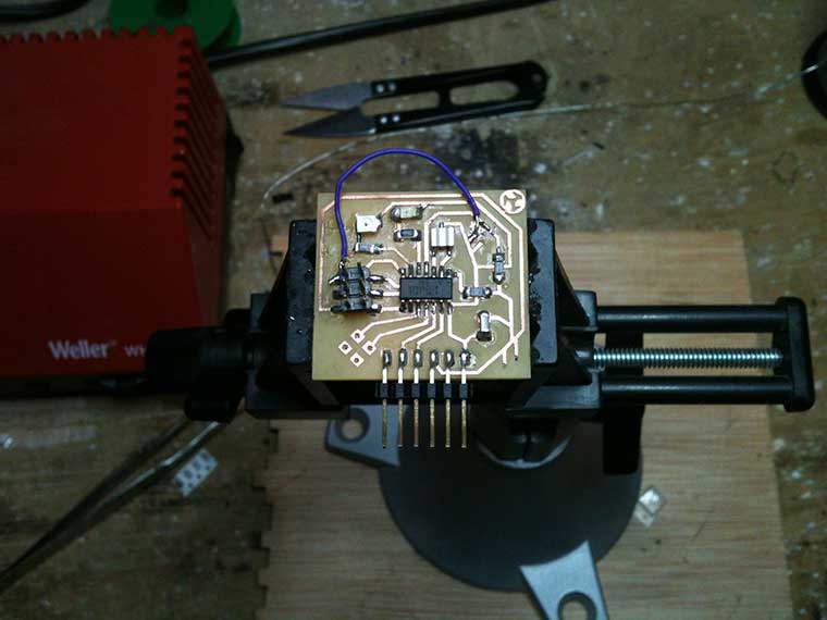
I exported the board's design in a 1000dpi monochrome .png image from Eagle and I opened it in Gimp to drawn a cutout contour and add my logo.
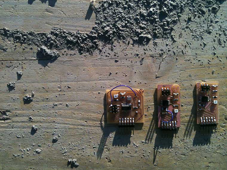
I milled it using Fab modules and Roland Modela as described in the electronic design week documentation.
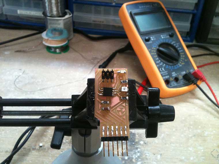
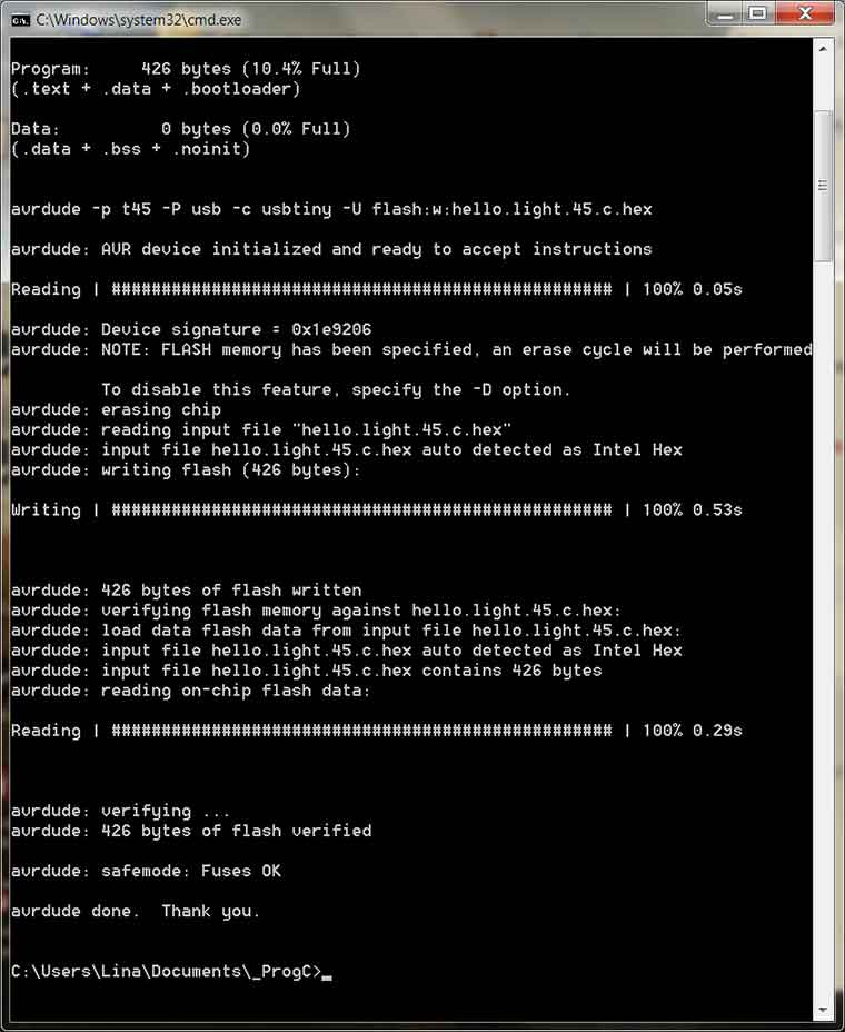
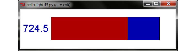
I went on programming the board using the Neil's Hello.light C code, to have a first feedback, as shown in Francesca's web site . Not without any trouble with Windows7 compatible softwares.And from the folder in wich I was saving all my programs I Flash the new Light.meIII board. !
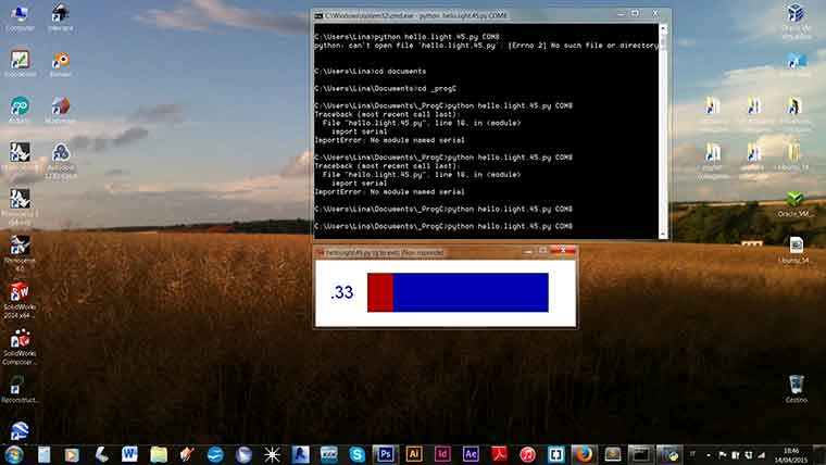
But once open the .py program I found the bar graphics not moving. There were not measuring data coming back from the sensor.
de-bugging 1
comparing IDE
To test Light.me III board I used Arduino IDE by flashing first a Blink program and than adapting the AnalogInput example. Unfortunately was not so easy as it seams. Sometimes Arduino IDE was giving me back that error:
0xff != 0x27
avrdude: verification error; content mismatch
every time with different values, randomly, even trying to programming different board with different examples After a long and confused research I realized that is a USBtiny Programmer failure message. I have to make a new programmer ASAP!
Anyway I reach a goal!
Looks like the sensor is well connected but no so sensitive.
Stating from the code just flashed I triyed to add a Serial Monitoring sequence:
int sensorPin = 3; // select the input pin for the potentiometer
int ledPin = 4; // select the pin for the LED
int sensorValue = 10; // variable to store the value coming from the sensor
//int outputValue = 0; // value output to the PWM (analog out)
void setup() {
// declare the ledPin as an OUTPUT:
pinMode(ledPin, OUTPUT);
pinMode(sensorPin, INPUT);
}
void loop() {
// read the value from the sensor:
sensorValue = analogRead(sensorPin);
// print the results to the serial monitor:
//outputValue = map(sensorValue, 0, 1023, 0, 255);
// turn the ledPin on
digitalWrite(ledPin, HIGH);
// stop the program for "sensorValue" milliseconds:
delay(sensorValue);
// turn the ledPin off:
digitalWrite(ledPin, LOW);
// stop the program for for "sensorValue" milliseconds:
delay(sensorValue);
}
( reading “ as <)
I triyed to add a Serial Monitoring sequence in the code: but even including the
AnalogInOutSerial.ino:32:3: error: 'Serial' was not declared in this scope
AnalogInOutSerial.ino: In function 'void loop()':
AnalogInOutSerial.ino:44:3: error: 'Serial' was not declared in this scope
Error compiling.
Has specified here, I re-defined the chars
//#include "NewSoftSerial.h"
int sensorPin = 3; // select the input pin for the potentiometer
int ledPin = 4; // select the pin for the LED
int sensorValue = 10; // variable to store the value coming from the sensor
int outputValue = 0; // value output to the PWM (analog out)
SoftwareSerial mySerial = SoftwareSerial(sensorPin, ledPin);
void setup() {
// declare the ledPin as an OUTPUT:
pinMode(ledPin, OUTPUT);
pinMode(sensorPin, INPUT);
mySerial.begin(9600);
}
void loop() {
// read the value from the sensor:
sensorValue = analogRead(sensorPin);
// print the results to the serial monitor:
//outputValue = map(sensorValue, 0, 1023, 0, 255);
mySerial.print("sensor = " );
mySerial.print(sensorValue);
mySerial.print("\t output = ");
mySerial.println(outputValue);
// turn the ledPin on
digitalWrite(ledPin, HIGH);
// stop the program for "sensorValue" milliseconds:
delay(sensorValue);
// turn the ledPin off:
digitalWrite(ledPin, LOW);
// stop the program for for "sensorValue" milliseconds:
delay(sensorValue);
}
In that way I didn't received back any error message,and the LED is blinking reacting to the light until the Serial Monitor windows is closed.Opening the Serial monitor the led stops and no data appear in the window
WARNING!:
Upgrading Arduino IDE to 1.6.3 version Tools setting was no able to find any PORT! The compiler was acting without give back any error until I opened serial monitor. I had to download Arduino 1.0.5 IDE zip. version to be able to program my board.
de-bugging 2
double check the hardware.
Finally I found a design error. A wire connecting RST micro controller's pin with RTS into FTDI.
Cut that wire I went back toi check the board with Neil's Hello.light.45.c program and finally running the hello.light.45.py program I saw the Data FLOW.
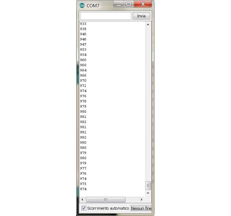
Back to Arduino IDE I was still in trouble. Serial monitor was still empty. But that time I had confirm that is just a code error. Asking help to Santy we start together minimalizing the code to the only Serial monitor definition. Checking in an “experimental” way the pins attributions we find the “magic code”!
const int rx = 3;
const int tx = 2;
int sensorPot = A3; // select the input pin for the lightsensor
int outputValue; // variable to store the value coming from the sensor
SoftwareSerial mySerial(rx, tx); // RX, TX
void setup()
{
//pinMode(sensorPot, INPUT);
mySerial.begin(4800);
}
void loop() // run over and over
{
outputValue = analogRead(sensorPot);
mySerial.println(outputValue);
delay(20);
}
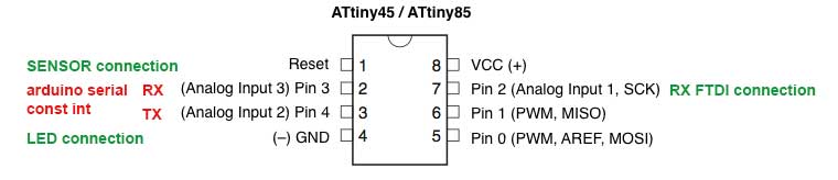
That make the Serial monitor comes ALIVE. Basically we recognize that even with different wire connection ( in Light.meIII RX connection is on pin 2 an there is not TX connection to FTDI) Arduino IDE recognize just those 2 pins as “exchanger” that is quite different from the reference scheme that I was using.
comparing hardware
#2_Tuning the (attiny 44) Hello.me's design
As planed designing the Hello.me Board during the electronic design week, I tried to tuned the ready made board changing the switch button with a light sensor with is relative resistor.
I test it first with Arduino's Fade exemple in order to verify if every connection had been restored.Than i tried with AnalogInput example finding that led blinking were not responding to light exposure. Than I tested it using Neil's Hello World C program, as shown in Francesca's web site and everything was going well.
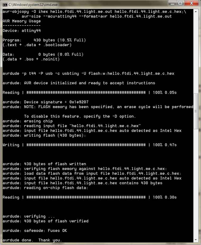
Adapting Hello light to attny44
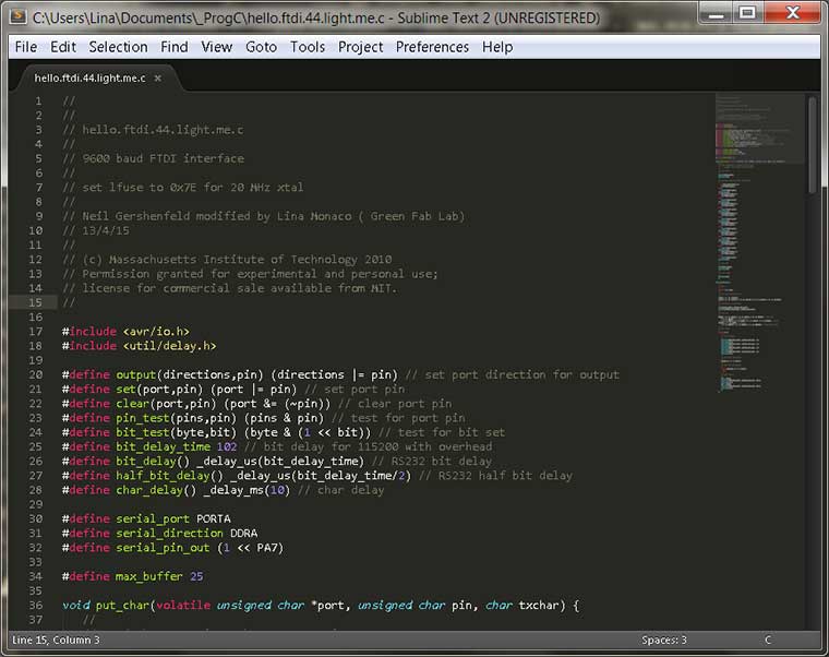
avr-gcc -mmcu=attiny44 -Wall -Os -DF_CPU=20000000 -I./ -o hello.ftdi.44.light.me .out hello.ftdi.44.light.me.c
hello.ftdi.44.light.me.c: In function 'main':
hello.ftdi.44.light.me.c:122: error: 'REFS2' undeclared (first use in this funct ion)
hello.ftdi.44.light.me.c:122: error: (Each undeclared identifier is reported onl y once
hello.ftdi.44.light.me.c:122: error: for each function it appears in.)
make: *** [hello.ftdi.44.light.me.out] Error 1
Having a look at the code I realised that is necessary reset the A/D sequence.
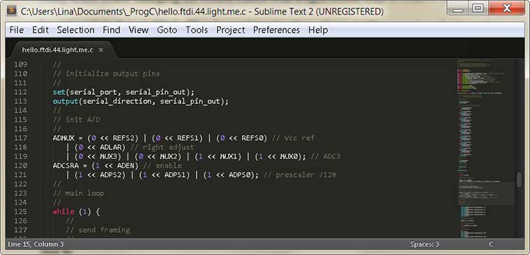
I checked the Attiny 45 data sheet looking for ADMUX and I found the ADMUX – ADC Multiplexer Selection Register :
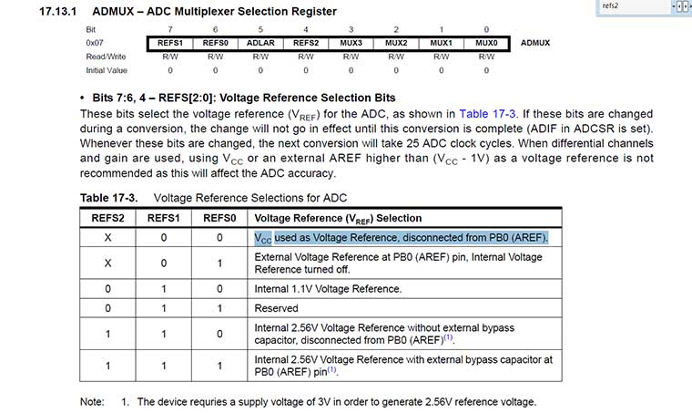
and I compared it with Attiny 44 data sheet
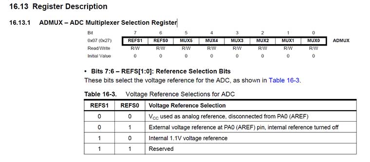
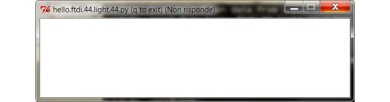
Finding that there is not REFS2 bit in attiny 44. SO i just tried to take it off the code. And re-flash the Hello.me board:
But running the hello.ftdi.44.light.py program it gave me back a white window...
Double checking the board I realized that the button design is not compatible with che light transistor+resistor scheme and I gave it up ...for the moment