Redraw the echo hello-world board
Redrawing the hello world board including a button and a led first of all i choose a button and a LED:
- LEDSMT 1206
- button: 6 mm switch
than I calculated the necessary resistor preceding the LED. Considering that source voltage using USB is always 5V, 1,8V diode forward voltage, and 10 mA asdiode forward current we obtain 330 Ohm as minimum resistor. Being the closer in our FabLab bigger I choose a
- RES 499 Ohm
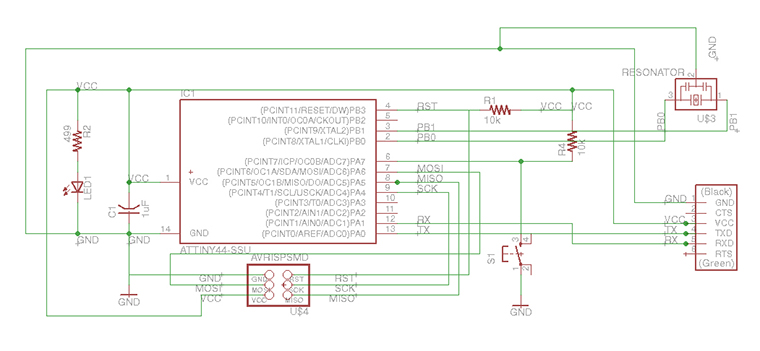
After choose the new components I define a first scheme with the necessary connections using >Eagle software .
First of all I tried to understand witch connections were fixed and witch interchangeable, especially relatively to at-tiny's pins. Looking at the data sheet I found that most of the pins of an at-tiny 44 have specific functions and can't be easily interchanged and that 2 of the remaining pins are PWN. I choose to catch the opportunity to give a fade property to the LED connecting it at one of those pins, and connect the button independently to the other.
In that way I hope to have more flexibility, controlling the LED from the micro-controller and ,maybe in the future, replace the button with a sensor.
Design adaptability
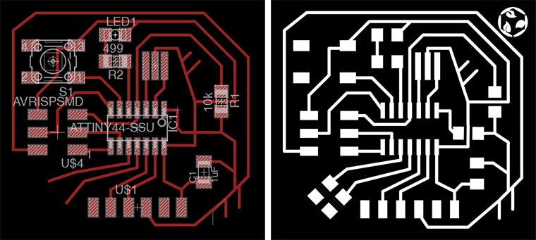
Going on I started to design the board on the way of flexibility. Designing the connections instead to optimize the surface of the board I choose to not entrap the 2 remaining attins pins leaving some room to design some open connection ending in soldering base having holes. Then I design other 4 opened connection to VCC and GND endings with holes in order to be able in the future to add more components, ( 2 LEDs in parallel or a led with his resistor ) and connect them by passing wired from the holes to the other side of the board.
I still don't know if that technique will works.
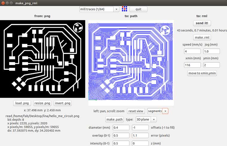
Milling settings
In order to Mill the Hello_ME board with holes I exported the board design with Eagle as image. Using Gimp I opened the .png file obtained, to draw the cutout file and the holes ones.
Than one by one I opened the3 files using Fab modules to milled theme with the Roland MD20 with the same procedure shown make the FabISP Valentine.
Before change the milling bit to cutout (1/32) I milled the holes using the 1/64 milling bit and setting 0,3mm cut depth.
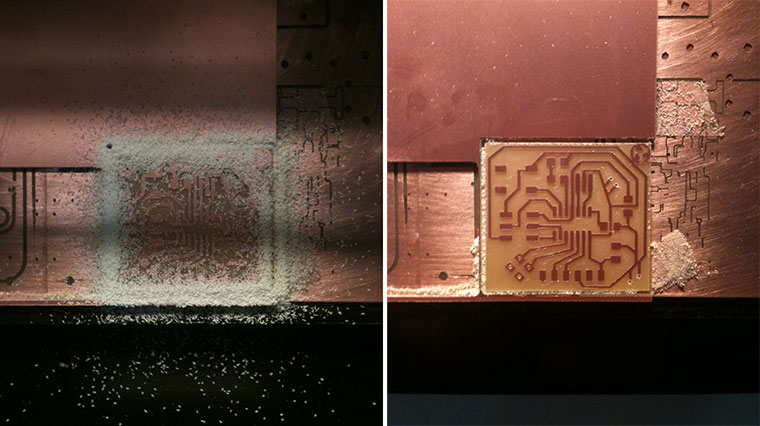
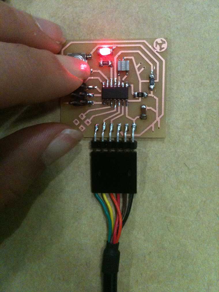
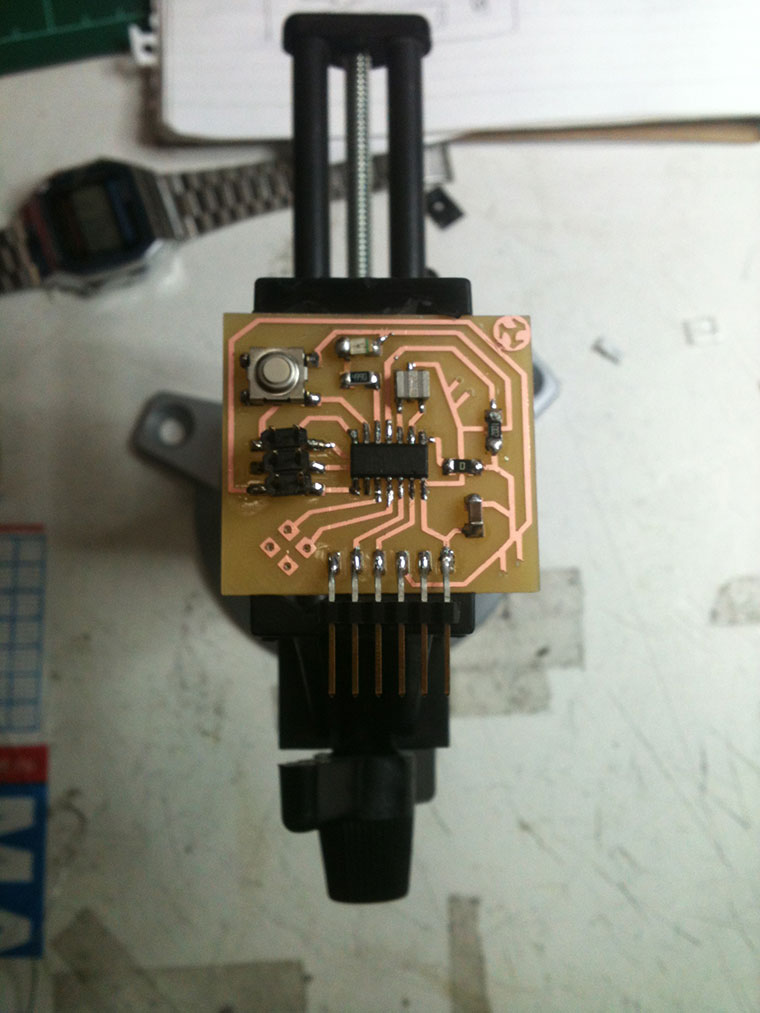
Soldering
As making the FabISP ValentineI proced soldering the components starting from the smaller to the bigger and fron the center going closer to the border. But that time was easier.
Testing
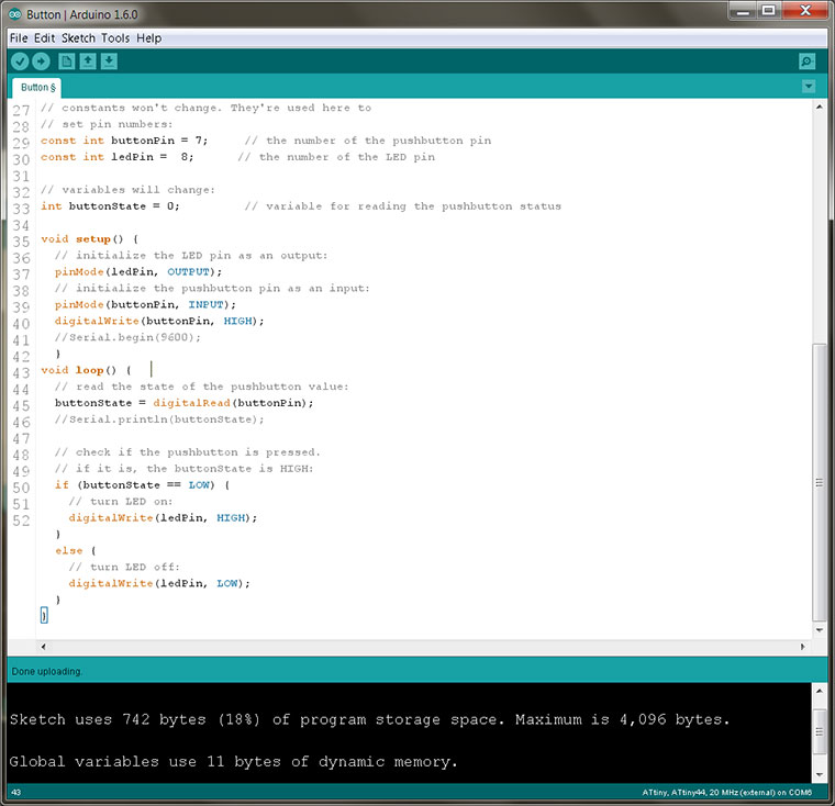
In order to test the new Hello_me board by using a Arduino's presets example I installed :
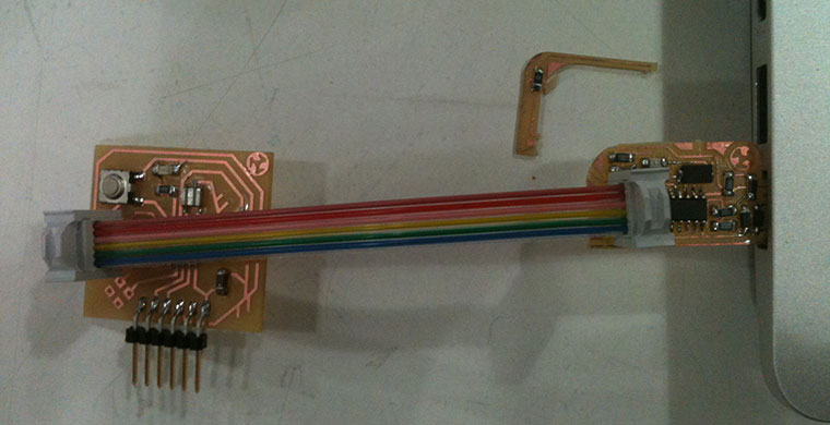
After that Arduino was able to communicate with the FabISP and by this program the Hello_me board. I had to add some code lines to make it compatible with the board, set the pins of LED and button and upload it.
see you next week