week 03.- 11/02/2015
COMPUTER CONTROLLED CUTTING
First I would like to clarify that this is not a module that has enrolled me to be completed . The Laser machines, since I met them, have me drawn much attention as a technology tool to support the implementation of projects, so I asked permission to the Director of FabLabBcn and Local Contact of the Fab Academy, Tomas Diez, to let me understand handling machines .
For this I made the assigment of "Computer Controlled Cutting " a week later to not interrupt the work of my colleagues.
Assigments
1. Design, make, and document a press-fit construction kit.
1. Press-fit construction kit
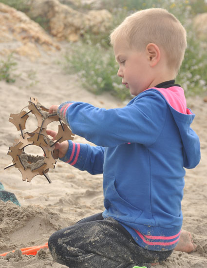
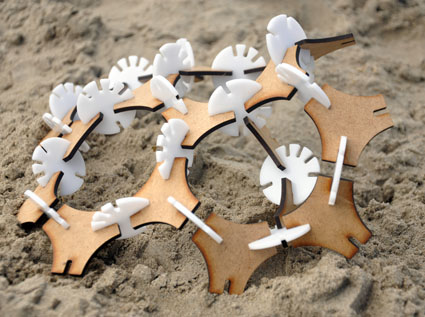
Based of Buckminster Fuller's Fly's Eye Dome, I tried to make a construction kit for this assigment.

I draw the object with Microstation in 2D.
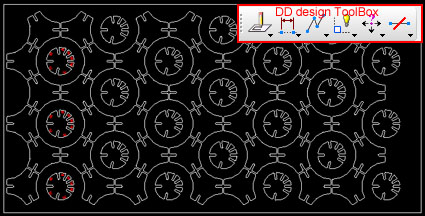
In order to realise that the exercise was of little size and to get to know the functioning of the laser, the powers and speeds, I started with the Lasercut Epilog Legend XT 36 75w. It was nice.
For the design pressure I chamfer the corners and left a hole of 2,9mm wide (in the case of the Cardboard), and fits perfectly.

In the classe of the day February 11 that gave Neil spoke to parameterize objects in Inkscape and reference all changes to one, so that changing a single parameter all joints are moved equally. Since then I was looking if the Microstation would had an option to do. And if so, the tool palette is called DD design, and is located in the menu Tools>Parametrics>DDdesign.

He also spoke of Antimony or Grasshoper for Rhino, which would be the equivalent to Generative Components in Bentley's software. It's something that will be watching.
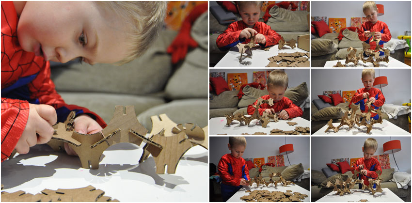
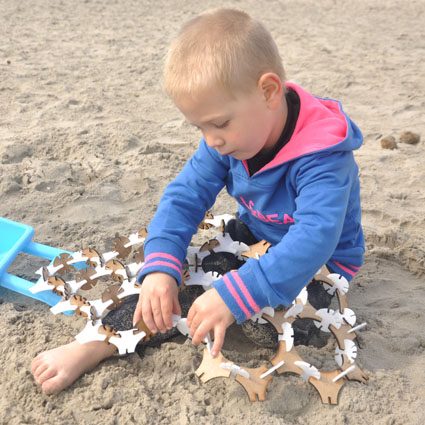
My 3 years old son had a great time making shapes with the pieces.
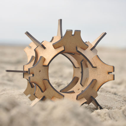
Later I tried with a DM 600x300x3mm board and another of PMMA. The hole in this case was 3mm wide and less large.
DOWNLOAD ARCHIVES
DGN file design cardboard of 3mm fit 2,7mm
DGN file design DM and PMMA of 3mm fit 2,9mm
Assigments
1. Design and print a object that could not be done substractively.
1.1 Designing parts for assembling a cubicuboctahedron in Microstation and export as .stl file.
1.2 Print different parts in MakerBot Replicator 2.
2. Scan and print an object.
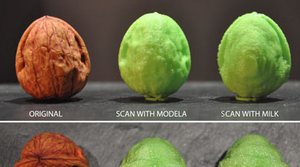
2.1 Scan walnut in MODELA with Dr. PICZA Software and also scan with MILK and use Photoshop to make a *.gif file and using the gif_stl converter of the Fab Modules.
2.2 Preparing meshes and build the element making simetry amd joined with Microstation.
2.3 Print it in Dimension.
1. 3D PRINTING
1.1. Design
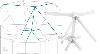
For the first part of the assigment, I decided to do some pieces that worked like the vertexs of a cubicuboctahedron. The assembling of the diferent parts allow to rebuild the platonic solid like a press-fit construction.
I modeled the object with Microstation (a Bentley Software). I used the solid operations to do it.
For the design pressure I left a margin of 0.2 mm between the parts , because with the fused deposition modeling (FDM) does not interpret the contour but the axis of the wire.
With the same program that I modeled, I export the *.stl file. To convert it well is necesary to select the element and this it has to be build in one piece. For that is necessary to do the Bolean operations. Unite, intersect and substract. The last operation it has to be unite to make a unique element.
Here is the result:

1.2. Print
I directly printed the file * .stl that was generated by exportation mode with Microstation.
Print with MakerBot Replicator 2 has been comfortable. The same software that has the machine is easy to use, because there are not many parameters to edit as other kinds RepRap printers (sometimes I print some design on a Prusa i3 with Slic3r Software for generated the G -code file and with Pronterface for interact with the parameters of the machine while is doing his job printing, like the temperatures of the extruder or of the bed).
I usually use software Pronterface to load the filament in the head, but MakerBot has the M button to make all actions directly from the machine.
I Printed with white PLA 1.75 mm. I used a Standard resolution, with a Filling = 15% , 2 layers of Shell and a height of layer = 0.2 mm.
It's also interesting, view the toolpath Visualization, to see how the printer will print layer by layer the piece.
16 minutes after click the buton Print and 2,97 g of material, the result was this:
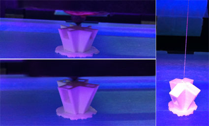
In the case of the bar element, I removed it when he had just been printed and arched surface. It would have been better to wait for it to cool.
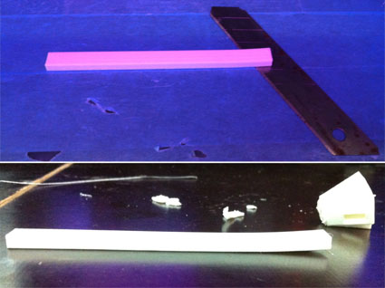
I also activated the box Raft in the first piece I printed, believing that the contact surface was insufficient, but it was not necessary, as in the second unclick Raft and perfectly printed.
The three pieces took between 15 and 17 minutes each one, and between 2,5 g and 3 g of PLA spent.
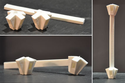
DOWNLOAD ARCHIVES
DGN file design 3D
STL file bar
STL file inside union
STL file outside union
2. 3D SCANNING
2.1. SCAN A WALNUT
2.1.1. SCANNING with MODELA mdx-20 of Roland DG Corporation with Dr. PICZA software.
The way the machine works is by moving a thin metal needle with a sensor in XYZ axis around the object and capturing the information of thevposicion at each point that detects in the surface.
Also need to grab the piece to scan on the board. In my case I used clay.
Recomendation: Set limits of your piece as accurate as possible and the scan time will be more optimal.
Described below are the steps I followed to the configuration with Dr.PICZA software:
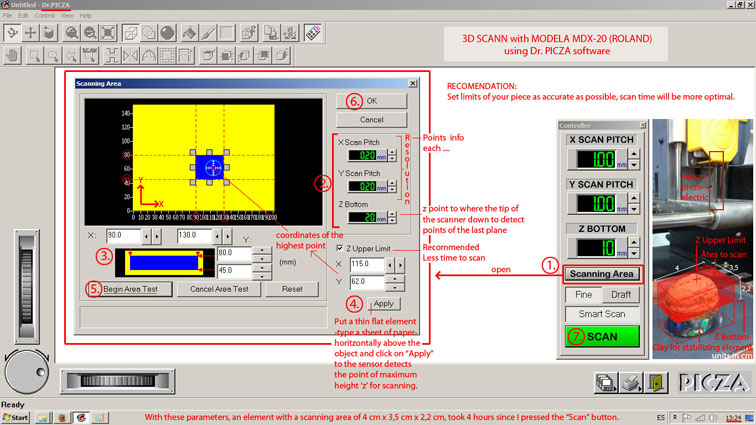
Steps according shown in the picture:
1. Click “Scanning Area” to open the control panel settings.
2. Set the desired resolution according to the texture of the piece. If you want mor detail the value should be lower but scan time will also be higher. Also sets the lowest ‘z’ point where the needle of the scan will reach.
3. Adjusts the boundaries of the area of the piece to scan indicating the maximum and minimum values ‘x’ and ‘y’.
4. Set point ‘z’ highter scan where the sensor should arrive. The coordinate ‘z’ is detected by the scanner when touch the object (Apply button).
5. Make a test before saying “OK” to verify that the settings are well defined.
6. “OK” . The parameters of Controller panel change.
7. “SCAN” to put the machine to work.
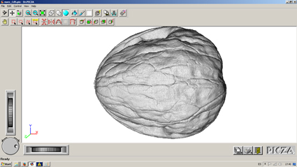
The scanning resolution obtained is shown in the image.
The area to scan were 4 cm x 3.35 cm and 2.2 cm for the z
The resolution Set was 0.2mm (it's possible up to 0.05mm) and it took a total of 4 hours. Initially the program said it would take 2:51.
DOWNLOAD ARCHIVES
DGN file wallnut in mm
STL file wallnut from modela
STL file edit wallnut
2.1.2. SCANNING with MILK
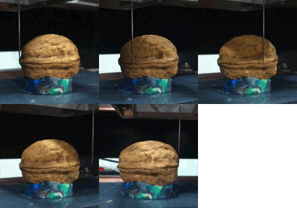
Thinking about the final resolution scanning element, I tried to get as many images sinking process element in milk and instead of making pictures, I decided to record the process and then take the necessary frames once modified to make the gif.
The process is recorded with a Panasonic HDC- TM90 with 25fps , with an extension of *.mp4 .
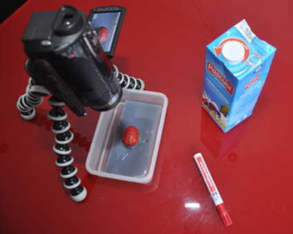
The nut does not weigh much and it floated the first test , so I fixed to the base with clay.
Once obtained the video , opened in Photoshop CS5. There was cut from the Animation window with the option of >Trim document duration to Work Area.
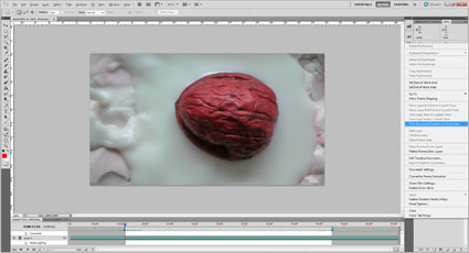
Then cut with the tool Video crop area adjusting element.
Subsequently several layers of adjustments were made to get the video in black and white and increase contrast.
Layer>New Adjustment Layer>Black & White
Layer>New Adjustment Layer>Levels
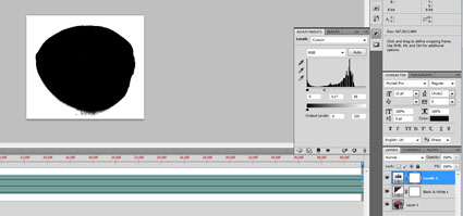
It is important to reverse the black and white, because white is the color will become black mesh and is hollow.
Layer>New Adjustment Layer>Invert
When generating the *.gif using a command File > Save for Web & Devices (or Alt + Shift + Ctrl + S), generated a gif that the program Fab Modules didn't understand the file, because it contained transparency and don't work well for now with it.
Milena
and I we were working on the same line and we always generated the same error, so we decided to prove two different ways. She would use automated programs to extract video frames (like ffmpeg, a good one recomended by Ferdi) and the batch mode of Gimp to edit faster all the images at once, turning them into black and white, etc ... And I decided to extract frames in *.jpg format to delete the alfa from video, since my video editing was already made with Photoshop adjustment layers and rebuild the *.gif from them and not from the video edited directly.
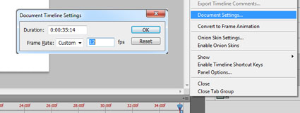
For this, I rescale the fps to have fewer images to load.
From the window of Animation > Document settings and document timeline settings popup where you can set the total frame rate appears. I wrote a 2, and so , for the 36 seconds of video that I had, would be 72 images.
I loaded these 72 images in Gimp and generated the *.gif.
Ensuring that was created in RGB mode without alpha channel associated, unclicking the Transparency parameter.(I also did it in these way in Photoshop CS5, but I don't understand why it didn't work.
The result:

Like said Tomas Robles by e-mail, to convertig *.gif to *.stl by FabModules, we have to use for now the command line, it does not have an associated GUI and we shoud use the terminal to make it work.
To go into the FabModules with the Comand in the Terminal, with the help of our instructor Ferdi, we write on it:
/opt/fabmodules/bin
To execute the Gif_Stl comand, write:
~/Documents/yourdirectory/file_name.gif(space)~/Documents/yourdirectory/file_name.stl

The process was fast, and in the end of the application, indicating that it had written to RGB.stl 79600 triangles.
The final file weighed was 3.79 Mb
There are some more parameters to control the Threshold and the 'z' size, aso we tried a few times to put different values and see what happens.
It was 21:30 am on Monday and we had made late so as FabModules gif_stl only worked with computer Fab Lab, I decided to resized the *.stl importing it in a Cad program (Microstation).
DOWNLOAD ARCHIVES
GIF file wallnut
STL file wallnut from fab modules
STL file edit wallnut from milk
2.2 Preparing meshes
With Microstation prepared the final mesh by symmetry and turning them into a single mesh with commands like operations boleana or tools like >stitch into mesh
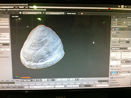
This week I have been many outstanding things to try, but among them is the issue of meshes with Blender, switching to Sculpt mode, and using the Smooth brush (S) to eliminates irregularities in the area of the mesh and selecting the Non Manifold (Shift+Ctrl+Alt+M) to see he holes and then selecting the bad parts to delete. And also with Edge Face (Ctrl+F) to fill gaps with triangles and all this kind of stuff. Ferdi made a refresher on Monday afternoon and I think worth to put me to practice. Also he recomend to us a tutorial called Blender Cookie. I have not delved too, but it seems a good resource.
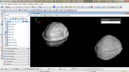
2.3 Print both scans and compare.
Finally I printed on the MakerBot with green PLA the edit mesh of the Modela Scan.
I put the nut on foot and click the draft option but not the supports one. To be the same material that had already printed parts of a cubicuboctahedron vertexs, I set the same parameters.
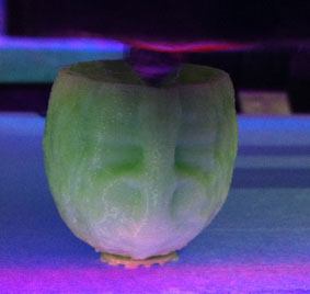
I would have liked to print with woodfil filament, but I went with the green for better reproduction of the element compared with the print of Modela scan to observe the same characteristics.
The file generated from Modela are printed as provided by the Software Makerbot, said 32' and it did in 35' and spent 7,72g of filament at a resolution of 0.2 with an infill of 15%, 2 Shell and therefore active Raft did not have sufficient basis to be printed without. Instead, the file generated from FabModules, possibly due to suboptimal later edition, said initially 33 minutes at a cost of 7,62g filament and otherwise identical to the previous parameters, and eventually took about 1 hour. The difference I think also it was for the file extension: The first one was *.stl and the second *.obj -a archive repaired automatically by Slic3r because I don't finish the mesh edition,I think it was a bad quick fix :(-.
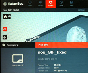
The complete two results in real size of the shape:
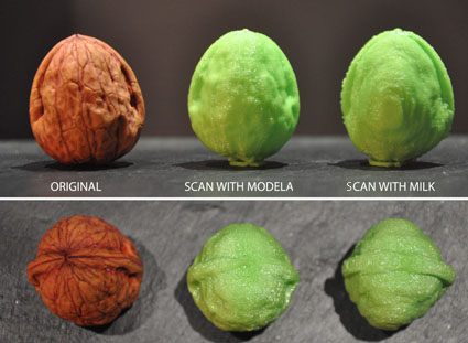
“I could live in a walnut shell and feel like the king of the universe”
________________________________________________________Hamlet
Assigments
1. Make something BIG.
1.1. Design
1.2 Process defining
1.3.- Drawing and prototyping
1.4.- Result prototyping
2. BIG
3. Conclusions
1. Make something BIG
To begin the exercise, I decided to design a chair. From this I had clear the shape, but did not know where to start when
for preparing documentation.
1.1. Design
I started with sketches, then to get the 3D model I was rolling with the angles, as this was not orthogonal. The hours modeling passed without result, seeing that I decided to make a cardboard model at 1:10, at least to clarify, in terms of ratios, etc ...
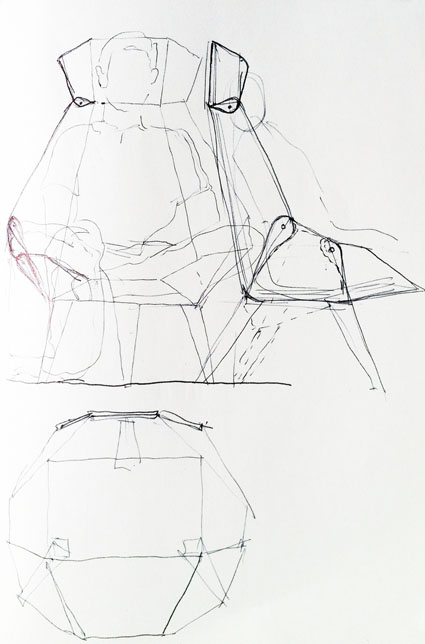
I decided to make the model with a thickness of 1mm equivalent to 1.5 cm board with whom I would work eventually, and the fact of working at scale, to go looking human proportions and see how fit each item.
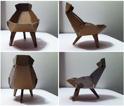
Finally, I had clear how, but not how to manufacture to solve different angles as variables and individual pleats.
Talking to Anastasisa and Ferdi, I was taught possibilities for the design, one posibility was modulating / triangulating the chair smaller, as the chaiseLounge of Pietro Leoni, parts were also watching the union of the Panels Chair by Sebastien Wierinck, then allowed to do different degrees as I had the prototype, we also look different unions that the company Lamello proposes to resolve any angle, and even talked to Miguel (an architect who worked with Anastasia doing the complete works of rehabilitation including furniture), above, had already made some furniture with non-orthogonal joints, but it turns out that the system he employed, served only to acute angles, because in the obtuse, the router undid the top material needed to clamping.
Finally, the range was so broad, I decided to look at possibilities of the router. The various points, shapes and angles predetermined different thicknesses bits and thus better understand the limitations for the realization of the exercice.
To the chair I liked the idea that it would made in one piece, and if possible avoid using the glue for binding of the various pieces, so as the model of the prototype (I did it with several parallel cuts in the area curve), I started to tell me about the folded-best it could apply and to think about the possible overlap of different pieces to work shear joints using a hindrance, not with ribs as he had seen it kind of is worked folding, because I liked the idea of popup.
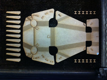
1.2 Process for defining
Had clear design goals, just missing it could be achievable!
I did a first test with the Epilog (Laser Machine) in a table DM 3mm thick. Were treated with parallel strips with equal distances between them. I am also interested to try the same lines with different inclinations, to see if I helped define new angles.
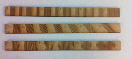
Due to the diverse and unknown angles geometry, decided to follow the way of prototyping and not of modeling in 3D, drawing the dropdown to a higher scale, to e 1: 5 and the DM would use as a material of 3mm thik, equivalent to 1.5 cm of the final wood (which at first was OSB, in view of the test, I think this will change).
While drawing, I gave the Kerf Chair designed by Boris Goldberg, who discover it gave me encouragement to continue on this walk.
1.3.- Drawing and prototyping.
I made many prototypes to this level, where above the fold out looking enough, and the final shape of the chair and size, to finish polishing the design.
He worked in most cases with separate lines wheelbase 7.5mm full-scale, than in 1:5 scale prototype amounted to 1.5mm and it was the one with the test strips had been more versatile and break seemed less.
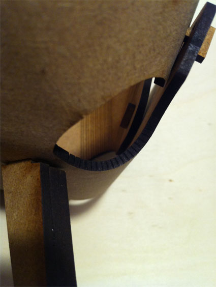
At the time of preparing the file I use Microstation (as it could have been done with AutoCAD, Inskape, Illustrator, SketchUp, among many others).
I worked various cutting depths according to the colors drawn on file, and also ordered according wanted which was first recorded and then execute the cutting. Then I try to describe it.
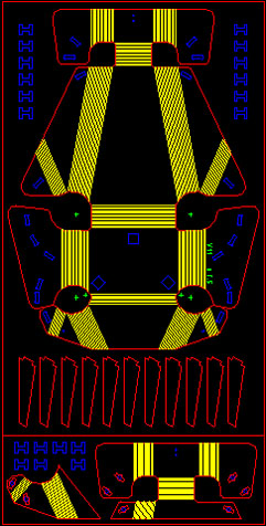
Engrave:
- The GREEN to the surface of the part taxed, for annotations and guide lines that served me to redefine forms, etc ...
- The YELLOW for parallel cuts than taxed slit, but they had to pass-it's all material thickness ... i tried that the material that was left to the fifth or sixth the end. To control the depth of the different lineas with the laser, it was difficult in the absence of 'z' to define, so I put about half power necessary to transfer the material. Later I will pass the data to cut employees.
Cuts:
- The BLUE color for internal smaller cuts.
- The RED color for contour cutting of the end pieces.
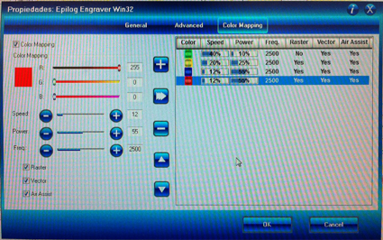
Once to send jobs to the Epilog, I use Rhino software from giving the following values (for DM 3mm) about Speed and Power depends of the colour.
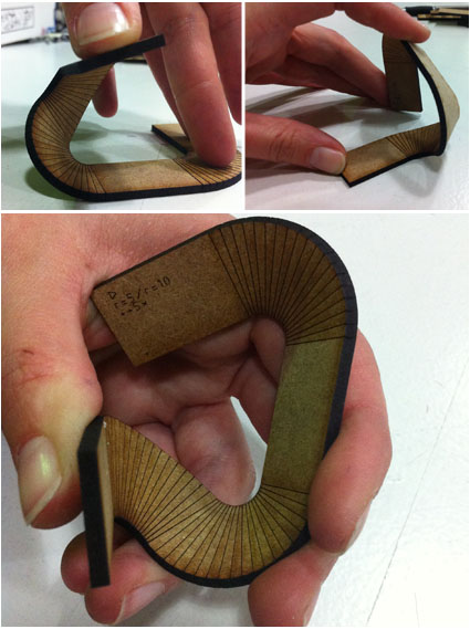
The result surprised me at the five prototype (in the previous 4 I did at the same time and I did not put too many lines for curvature and I was the almost flat element). It works! Bending it inside always, not outside or it would break.
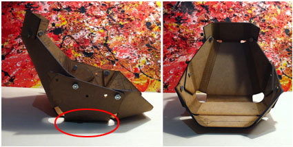
However formally had very deep base and part of the head was barely room to nail it with the wing shoulder. So the following models, change depending the formal and structural factors, as for example the part of the head, that was necessary to exist as locking wing chair, like the deformation was high and produced a moment of very high rotation in the arm.
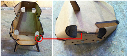
In the number 10 prototype I are tight to fit into the width of a board estàndard of 2500x1250 (in mm), because in the above the average piece about 1500mm wide. Upon are tight and some scale as the entire chair was something Oversized, I did not realize that losing the constant separation between paral·lelas folding lines, and staying 6mm or so, they began to break.
Finally regained line spacing 7.5mm -in-scale prototype were 1,5mm- and it worked pretty well.
Also added from the prototype 10 unions, instead of being locked with screws with male and female, would become through a piece of the same material as the seat.
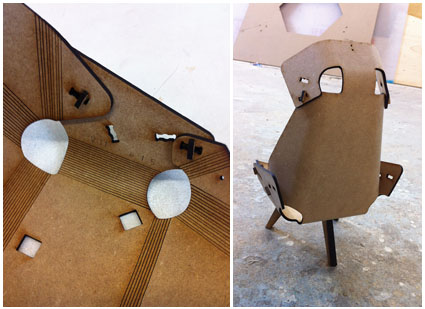
To put the unions the possibility of converting the chair recliner and obtain different positions for the back or headrest emerged.

1.4.- Result prototyping
The result of the prototype scale 1: 5 with DM 3mm and 7.5mm spacing between overhead lines crease, was continuous and did not break. By doing strength to work chair compression, these linias not broke, so the material DM qual werent working well be the direction of the lines, regardless of the grain of the wood, as in the DM no direction thereof to be resin mixed with sawdust.
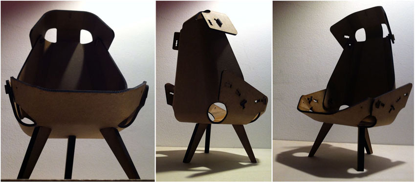
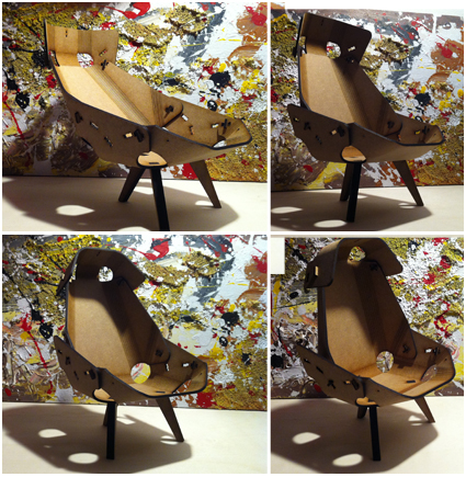
A chair lacks some stability, so for the last design, I decided to put 4 legs (not 3) and remove the last degree of recline.
2. BIG
The exercise was to build something big, and the idea was to make the chair with the milling machine like Shop Bot. I had requested an OSB board (before starting with the design of exercise and see the characteristics and to analyze the properties of each material).
Because of the time involved in the design phase, I test the OSB material at 28 of march. For that, I use the milling machine model name Precix, that it's also a milling machine to CNC of 3 axes and also work with archives GeCode or CAM.
In order to create the toolpath , it could do with commercial software FeaturCam or MasterCam type. Also with Fab modules with the option of Tool Path generator to create the * .stl if the model were 3D or GeCode should be 2D . According to the talk that Ferdi gave us no Monday 23 of march, could also be done with Inkscape more the plugIn "Path to Gcode", or the OpenSCAM (free open source) or the RhinoCAM , which is the software I finally used.
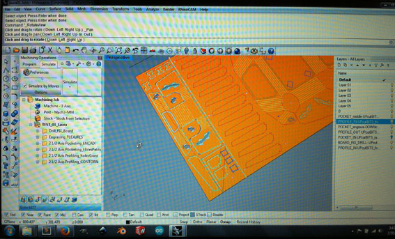
Soon I hope to put the steps I followed to RhinoCAM and if I can, also I would do with the plugIn mentioned in the previous paragraph, for Inkscape.
When the ToolPath are configurated, then we exported the Posted Output file in *.nc extension for current Post fo Mach 3MM.
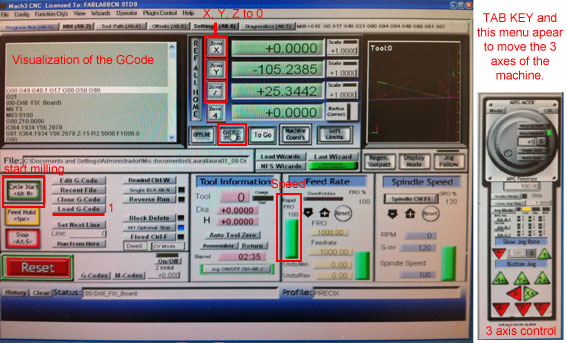
To control the machine we use the Mach3 software.
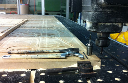
This image shows the necessary tools for changing the mills. I used a 3mm drill to fix the board on the surface, 3mm mill for the kerfing cuts and 6mm for the rest (engraving, inside and outside cuts).
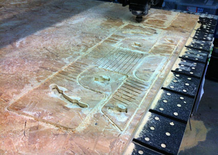
In order to generate the ToolPath both the Inkscape as in the Rhino, I'd many problems in the recognition of "Polyline" (in Microstation I suse the tool "Create Complex Shape", similar to the tool "Create Region"), it did not seem compatible with the two programs. After searching various conversions in the file, the solution was to explode this kind of line and put it together again with the "Join" command in Rhino.
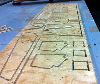
I decide to use Dog-bone for the chair legs (outside cuts) and T-bone for the holes to put the chair legs at the bottom of the chair (inside cuts), only to see the diference of the shapes with 90º.
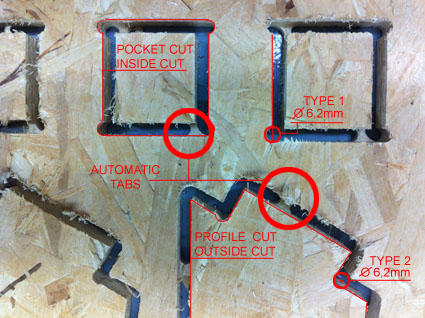
Testing diferent lines of flexures.
On a board of 15mm thick, I engraved with a 3mm mill until z=-12, paral·lel cuts by axis of 15mm. Also the same by axis of a 7,5mm (half the previous). The little ones broken during the milling job, the other ones resisted during the job, but the material doesn't permit to flex.
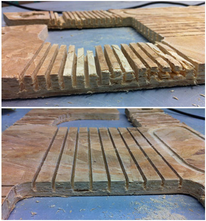
I think the result obtained in DM can be more suitable. I'll ask for another board and make my test in the future.
Blending test with OSB. Two diferent space between lines.

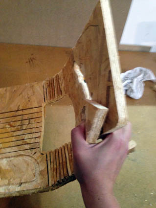
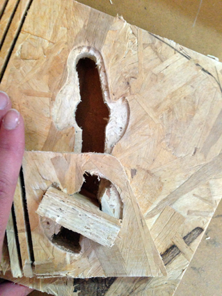
... And checking the attachment of the legs.
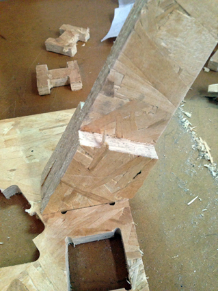
Finaly, when I get the right material (DM 12 mm) in Lab I'll do realy the final whole chair. -During july we said.-
DOWNLOAD ARCHIVES
FILE IN RHINO WITH RHINOCAM PARAMETERS:
3DM file test
GCODE FOR PRECIX:
NC file drill fix board
NC file engraving flexures
NC file axis pocketing fit
NC file axis pocketing little holes
NC file axis profiling big holes
NC file axis profiling contourn
GCODE FOR SHOP BOT:
NC file drill fix board
NC file engraving flexures
NC file axis pocketing fit
NC file axis pocketing little holes
NC file axis profiling big holes
NC file axis profiling contourn
3. Conclusions
I have yet to use in the laser for the prototype supposedly would not be as suitable for the kerf bending work, as there are no values 'z' and difficult would result to the width of the hole on a larger scale, but I think that is an area to investigate, as the Cutting is very precise and views that smaller-scale prototype has been made possible ... I think now, and why not?
Also, when I did the first test of curvatures, not only played with parallel overhead lines between them, but also played with angles. The result and its deformation makes you feel like to inquire more about this subject once the assigments end.
Assigments
1. Design a 3D mold.
2. Machine it.
3. Cast parts from it.
1. Design a 3D mold.
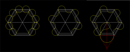
To begin the exercise, I decided to design a piece that permits make a large surface with his clones. The following images show the design process.
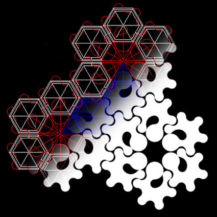
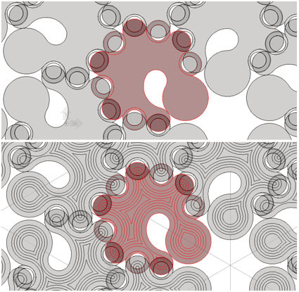
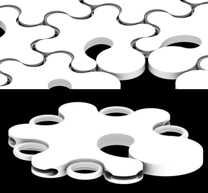
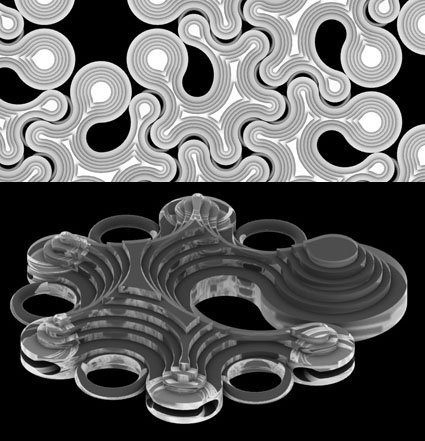
With the model and Boolean options and calculation tools that have the program I could measure the volume of the part to better adjust the mix of molding & casting.
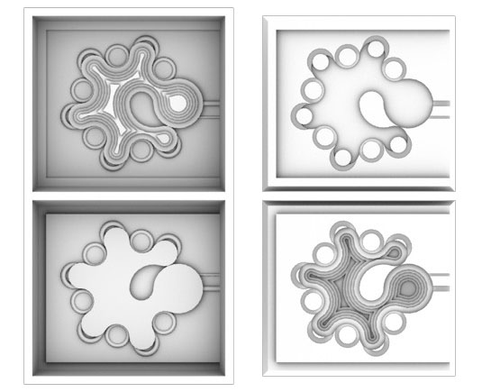
DOWNLOAD ARCHIVES
DGN file design
STL file for premold in wax
2. Machine it.
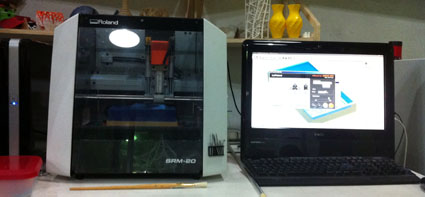
I used a desktop mill, a Roland SRM-20 machine to make the pre-mold of Wax.
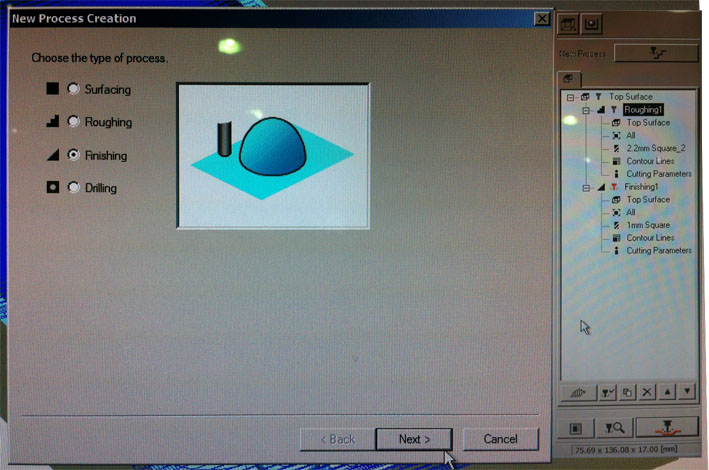
To convert the file *.stl into gcode I use the "Modela Player 4" software.First, with the help of Ferdi, we configured the Roughing with a 2,2mm mill.
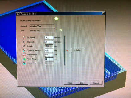
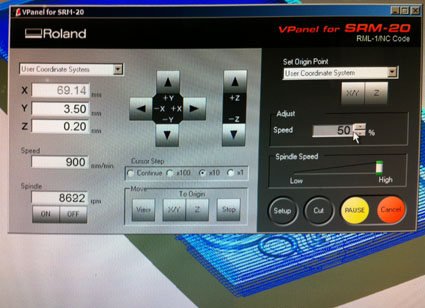
Then we indicate the x, y and z origine with the Vpanel acording to the position of the mill.
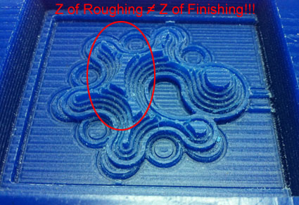
When Roland finished the Roughing, we adjust the parameters of the Finishing with a 1mm mill.

We change the mill drill, but when we adjust the z origin, goes more deeper and then caused an error in the finish.
3. Cast parts from it.
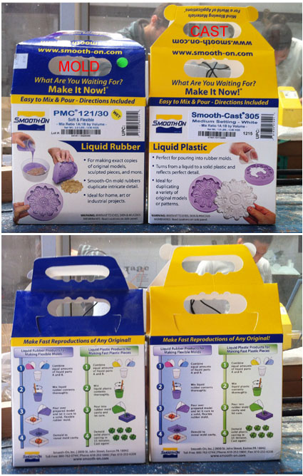
In order to make a mold I used a Smooth-On PMC 121/30 product, that was a soft and flexible urethane rubber. And for the cast parts I used a Smooth-Cast 305. The first one dried in 14 hours and the second one in 30 minutes.
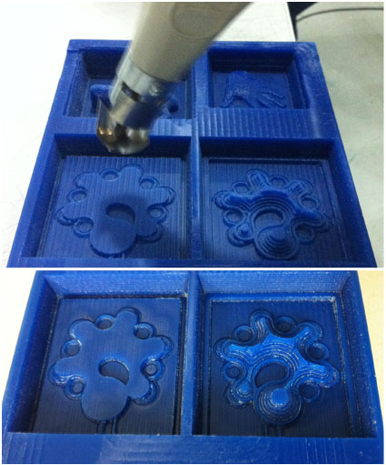
To remove excess wax particles, we use the heat gun.
After we made the equal mixture of Part A to Part B of plastic for mold, trying not ever mix the utensils used in each pot.
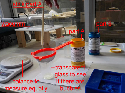
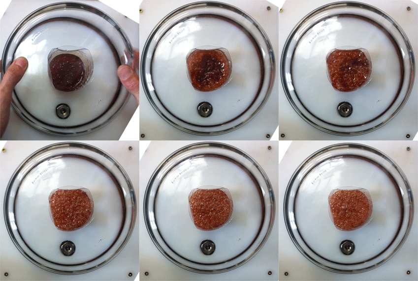
Part of the mixture was not too good so we decided to strain to avoid clots. This also had many bubbles so we put it under pressure to remove bubbles.
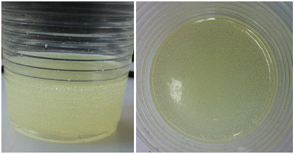
We mix well component A with B (which were equally).
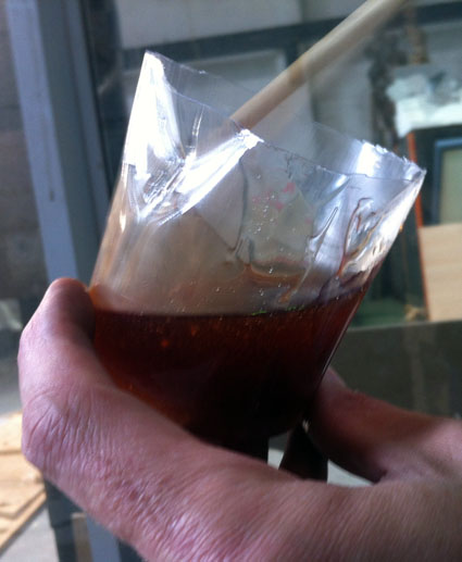
Then we wacum another time to remove the remaining bubbles in the mixture.
Finaly we poured the mixture into the preform.
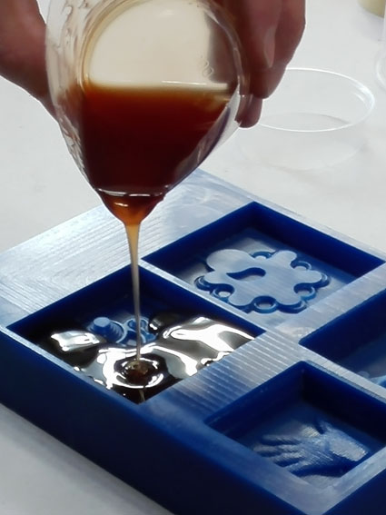
At first when pulling from above I was seen as many bubbles were made, but when unmolding (the next day)... the mold had been well.
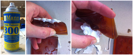
For cast, we use the Smooth-Cast 305 that I mentioned before. Before closing the mold, I put easy removal spray, as some colleagues who had done hours earlier had a bad experience with the part of unmolding.
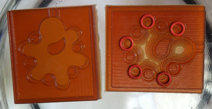
Also I placed five silicone rubber washers 6x2 ( 70VMQ000 ) that I had bought in a store of industrial supplies called Asteva SL that was near the FabLab. In this way I get the hollow interior of the parts designed without an intermediate mold.
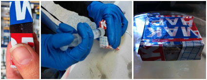
Finaly I Mix equally the two parts of the liquid plastic 1A:1B by volume or 100A:90B by weight, and with the help of a syringe I introduced it into the mold.
After 30 minutes...
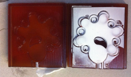
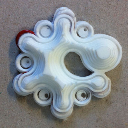
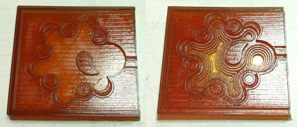
Once I also removed the silicone grommets, the result (much improved) is this.
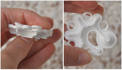
When I Closed the mold and because it was so soft, it was shifted to one side relative to each other a little bit, so there is a slight displacement in the xy plane of the workpiece.
