
Output Devices
April 15, 2015
Assignment:
Add an output device to a microcontroller board you've designed and program it to do something.
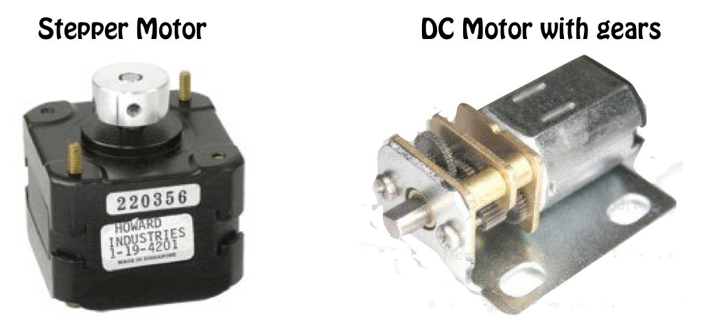
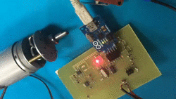
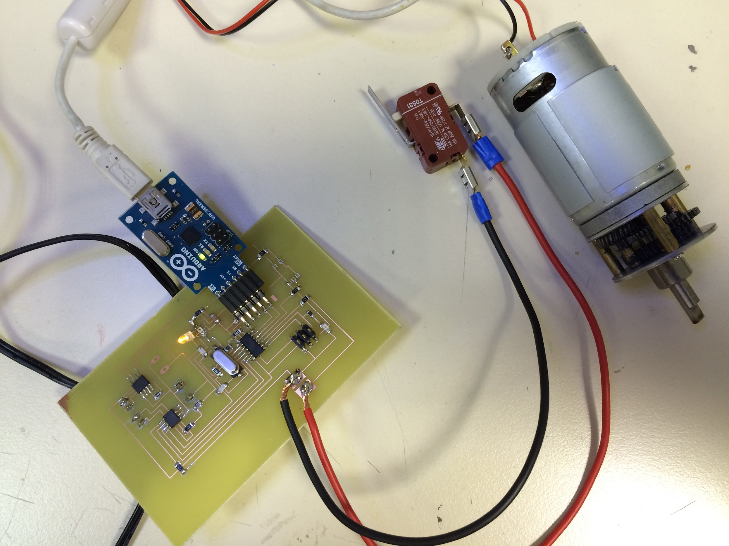
For this week's assignment I will try to design/build a PCB and code it to control both a stepper motor and a DC motor with gears. The DC motor with gears have reduction gear trains capable of providing high torque at relatively low shaft speed or revolutions per minute (RPM). A stepper motor on the other hand is a brushless DC electric motor that divides a full rotation into a number of equal steps. The motor's position can then be commanded to move and hold at one of these steps without any feedback sensor (an open-loop controller), as long as the motor is carefully sized to the application.
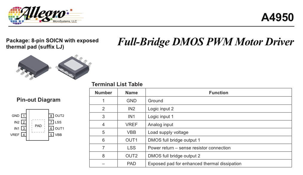
I will be using the above Motor Driver or H Bridge to control the motors. An H bridge is an electronic circuit that enables a voltage to be applied across a load in either direction. These circuits are used in order to allow DC motors to run forwards and backwards.
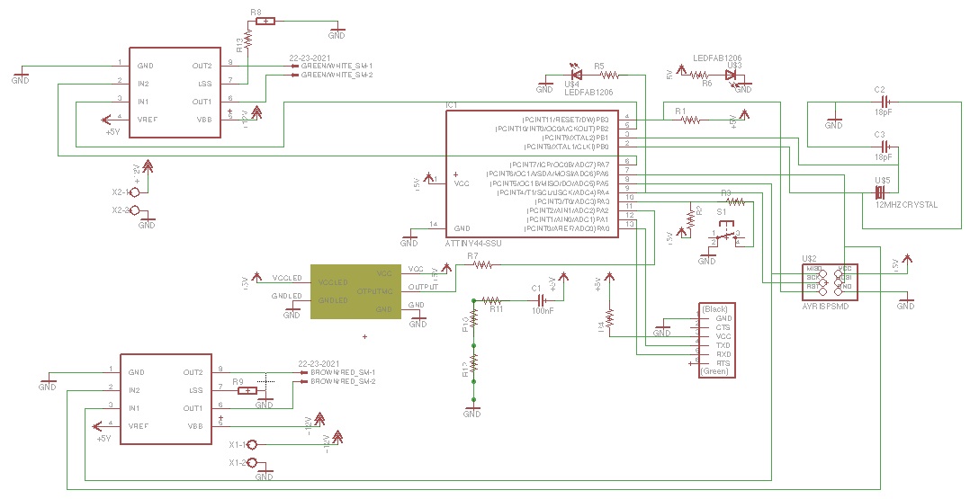
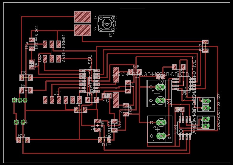
Output Devices PCB Design:
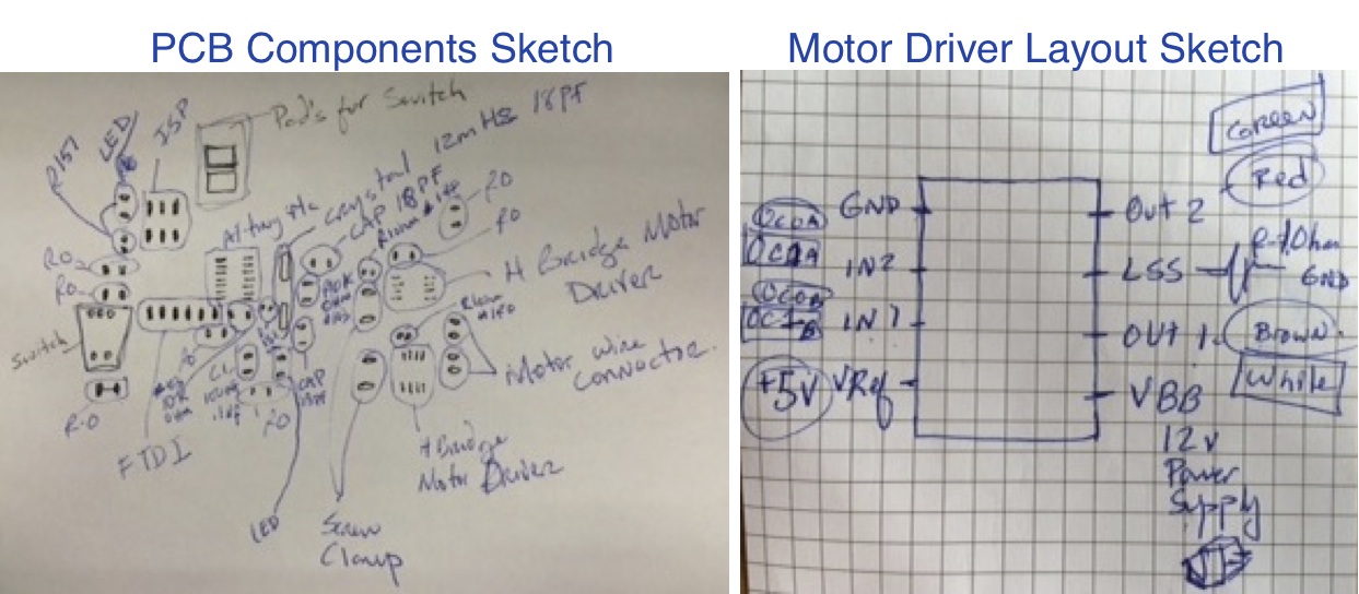
After reading the data sheets of the components I am to use I proceeded to design the schematics of my new PCB. Followed by arranging an adequate PCB layout. I then etched the PCB and started soldering the different components.
Here are the links to my Output Devices PCB Files:
Output Devices PCB Schedule Design
Output Devices PCB Board Design
Output Devices PCB Etching Mask
Programming:
The following program will make the motors turn on and gradually increase its speed until reaching full speed, making a pause and then repeating code endlessly.
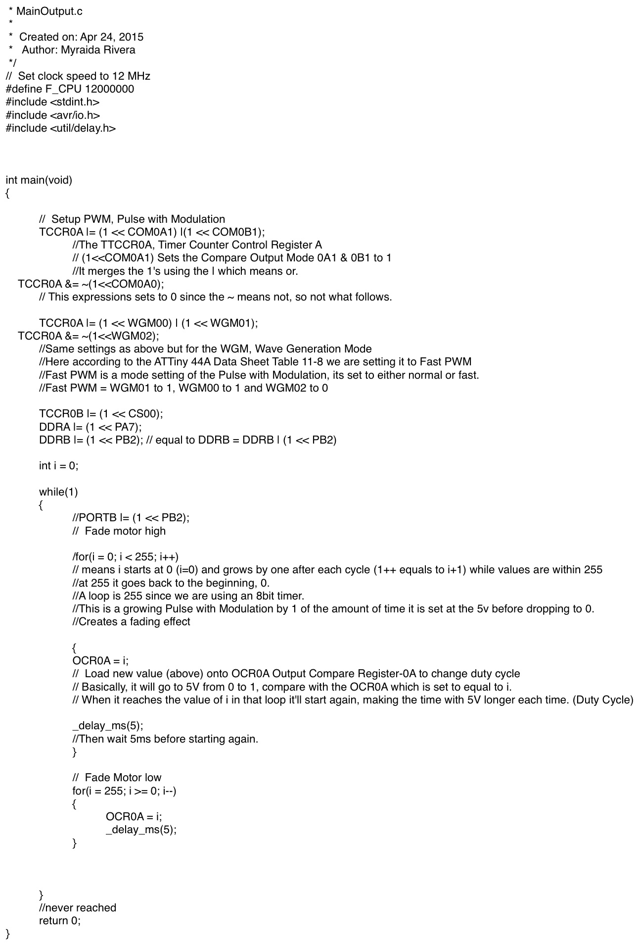
Here is the link to my Output Devices C-Code File:
Output Devices C-Code
