electronics production
assignment
The assignment for this week is to FabISP board that we will use through out the rest of the program. We have to mill the board, stuff it with components and program it.
fabisp
The FabISP is an in-system programmer for AVR microcontrollers, designed for production within a FabLab. It allows us to program the microcontrollers on other boards we make.
milling the board
We use two files to mill the board. Below on the left we have a picture of the file to mill the traces, and on the left is the file to cut out the board.

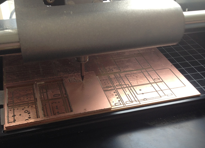
When setting up the machine you have to make sure to set the "0" point, and that you are using the right head.We use 2 different heads on the maschine for the 2 different purposes. The finer head is to mill the traces and the bigger one to cut the outlines of the board.
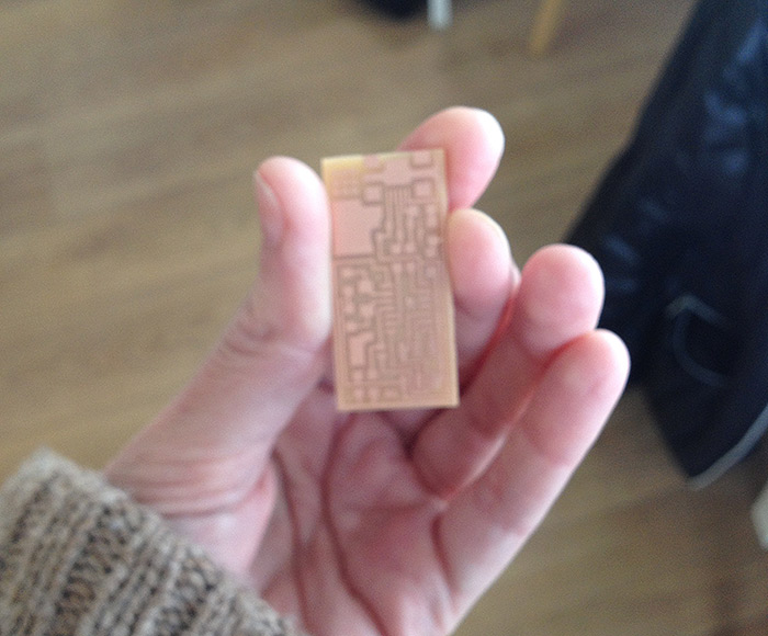
Above is a picture of the naked board. (Excuse the focus)
stuffing the board
Next we have to stuff the board with the components and solder them. The components are many and small and a lot of them look the same. Organisation seems to be very important in keeping the components.
I started with printing out the FabISP board diagram and writing down all the components down on a piece of paper and putting adhesive tape with the glue side up next to my list of components. That way I could easily organize the components and have them all in one place.
Components:
I used a magnifying glass with a light, something to hold the tool and a soldering tool.
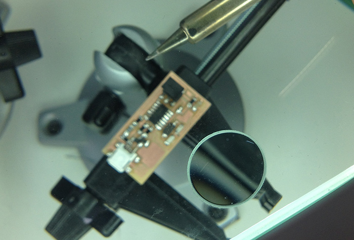
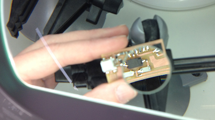
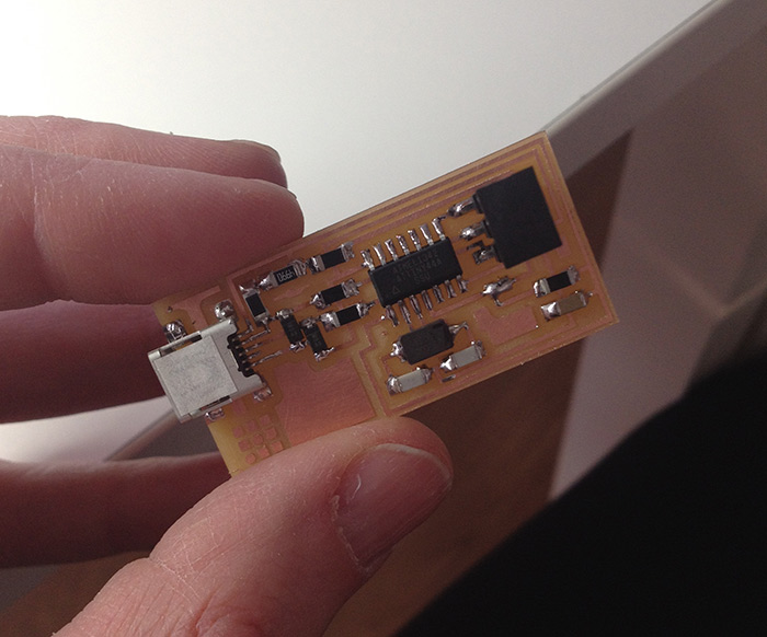
I started with soldering the USB chip. I was told that was the most important and hard. Then worked my way down untill I got to the "spider chip" (microcontroller). I tried to solder the hard bits first and then working my way outwards. The microcontroller (spider) and the diodes have polarity and have to turn a certain way. The microcontroller has a little circle in one of the corner which has to turn the same way as the circle in the traces of the board (also in the diagram of the board). The diodes have a tiny line which need to be on the C side of the diagram. I had to use the desoldering braid a few times. It went quite well, and Bas said I was a natural :D .
smoke test
I used the multimeter to check all the connections. By putting the 2 meters to ground solder blobs and seeing if the meter beebs. And then repeat on all the "V" solder blobs. All the connections worked fine.
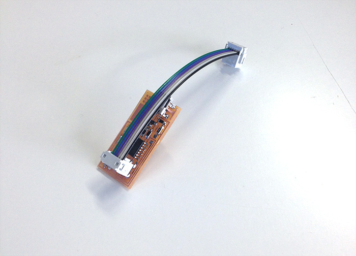
programming
I connected the board through the usb to the computer then with a rainbow lead to Bas´s board and back to the computer with a usb.  I did all the steps to this tutorial on programming. When I had finished programming it and checking it, I attached my own rainbow lead to the board: