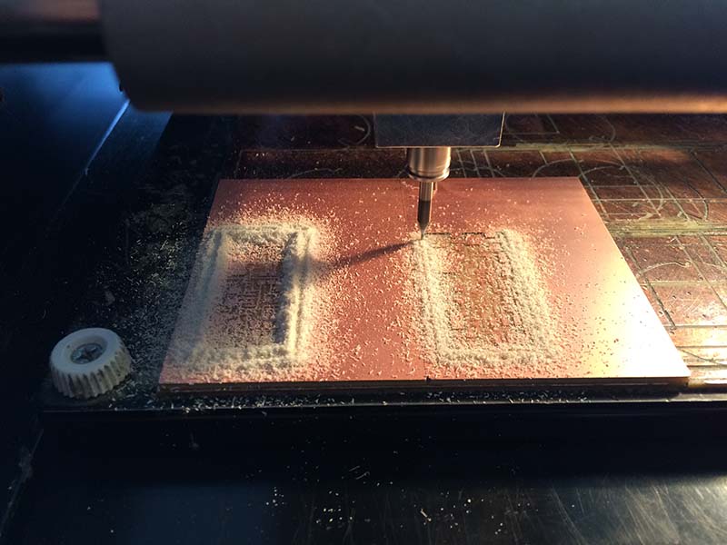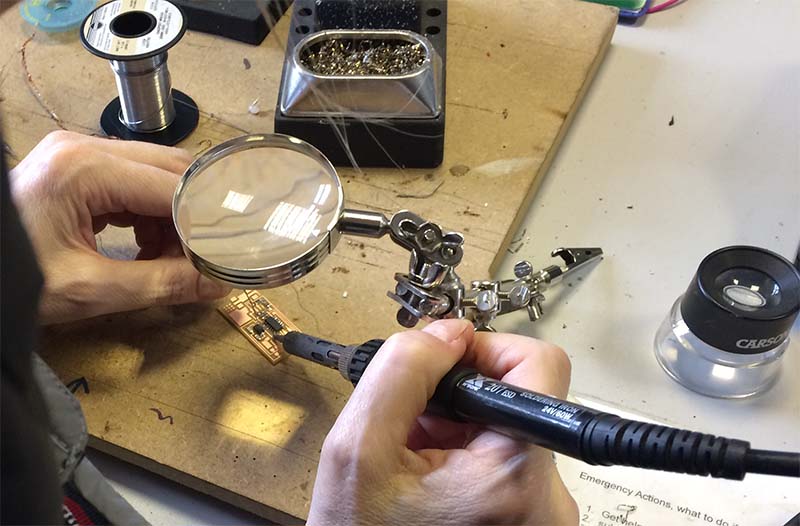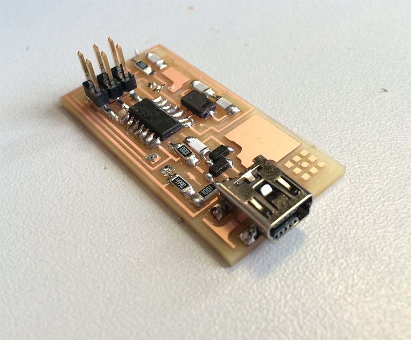

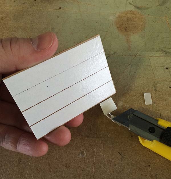
This week's purpose is to learn to produce printed-circuit-boards. The method used is milling in a plate coated with copper, so that in the end that appears a circuit of thin copper tracks. Here after soldering various surface mount components on the plate, so you end up with a functional product.
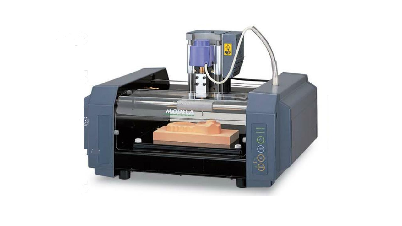
In order to obtain a good result, it is necessary to use a CNC milling machine with a relatively high precision. Here uses a Roland MDX-20th, It has a precision up to 0.025 mm / step.
Before one can begin to mill, you must prepare the router by switching to the right tool calibrate z0, and insert an object too mill.
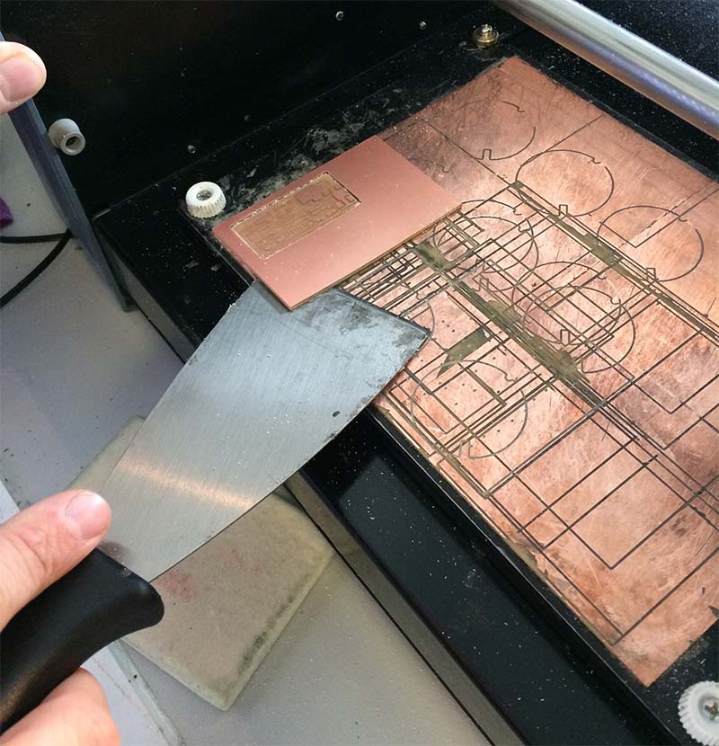
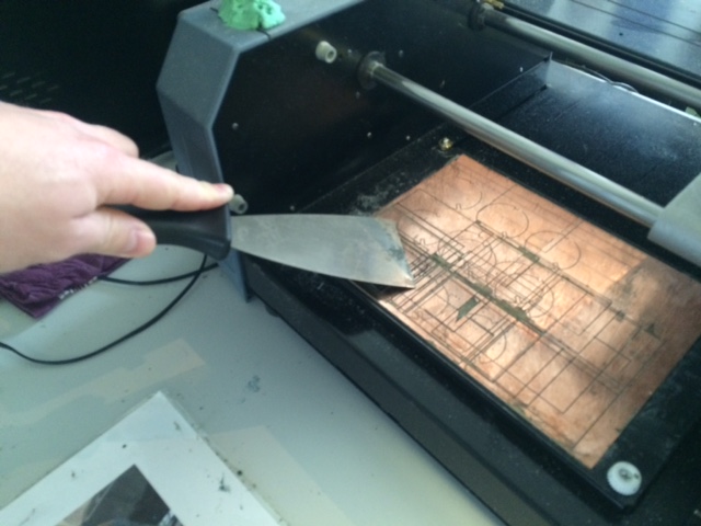
First, clean the workspace. There can sit some glue residue or other imperfections from previous milling jobs. These are removed with rubbing alcohol and a spatula.
When the workspace is clean, the object you want to mill can be inserted. To do this, it gets the double adhesive tape on the back.
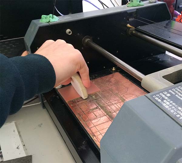
The plate can now be placed in the cutter. It is important that you place the plate in relation to the machine zero, which is located at the bottom left corner. One can manipulate the software to start somewhere else than zero, but it is still important to know the exact location of the object. Once the item placed where you want it, you can use a sponge to press it into place. The sponge helps to distribute pressure evenly.
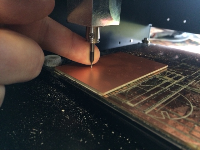
The only thing left for you to do before start setting up the software, is to switch to the tool you want to use, and set the z-height. This is done at the same time.
If there is a tool in the machine in advance, loosen the screws and remove the tool. It is important that you look at the tool does not fall out when loosening the screws, as even a small drop down on the hard workspace can crack the tip of the tool. When the old tool is removed, you can now insert the new one. The tool inserts so that only the cuttingflute sticks out, and then tighten the screws. Then move the tool to a posision above the object you want to mill. The tool is lowered so there are approximately 2 mm clearance on the z-axis. Loosen the screws, and it is now again important to keep a finger on the tool so it does not drop down. The tool is lowered carefully down to the surface of the object and the screws tightened again whilst applying downward pressure to keep the tool in contact with the copper plate. Now z-axis zero point at the object's surface.