
Final Project
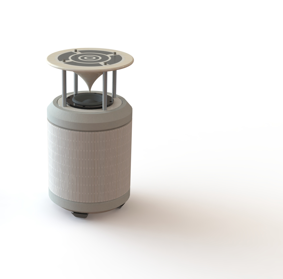
Here would like to go through the development and making of my final project. In the very beginning of the academy, I wanted to make a cheap "workshop-friendly" speaker. As I began to develop the concept and made a lot of research on speakers, I changed my mind. I decided to try to make a speaker different from other speakers in the way it was made. I wanted to try concrete as an material and shape it in way that would make the music sound better. While the design came in to form, I decided on the name "cone-speaker" because of the cone in the top.
The cabinet
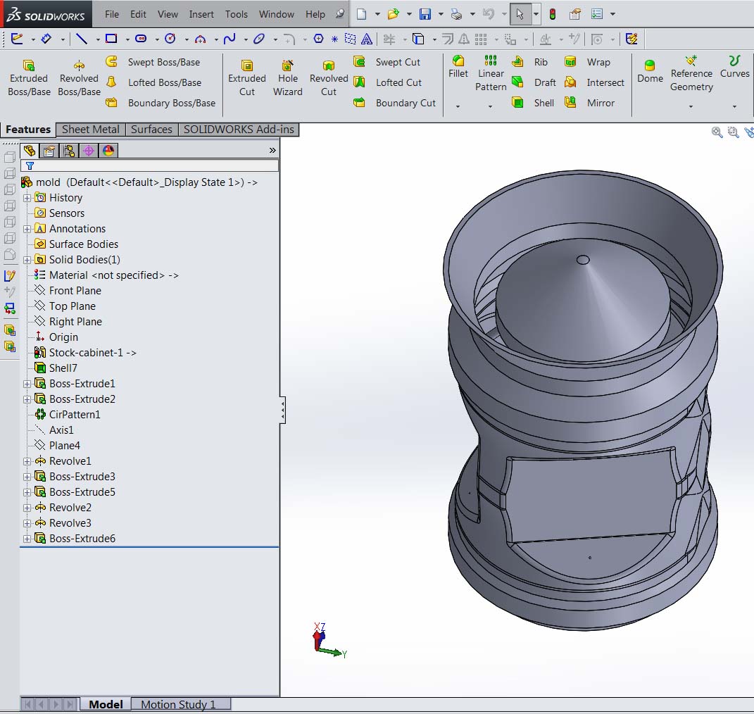
The cabinet has many function. One is to give the sound depth , another to enclosure the speaker it self, and in my case also the amplifier(active speaker). In my first concept seen in "final project proposal" I had the idea to use plywood with living-hinges as a cover. I liked that idea so much, that I stocked to it and have used it in the final design, because of the living-hinge it felt naturally to make a cylinder kind of shape. To draw the cabinet, I had to draw the speaker first. I did that by using some blueprints from the company webpage.
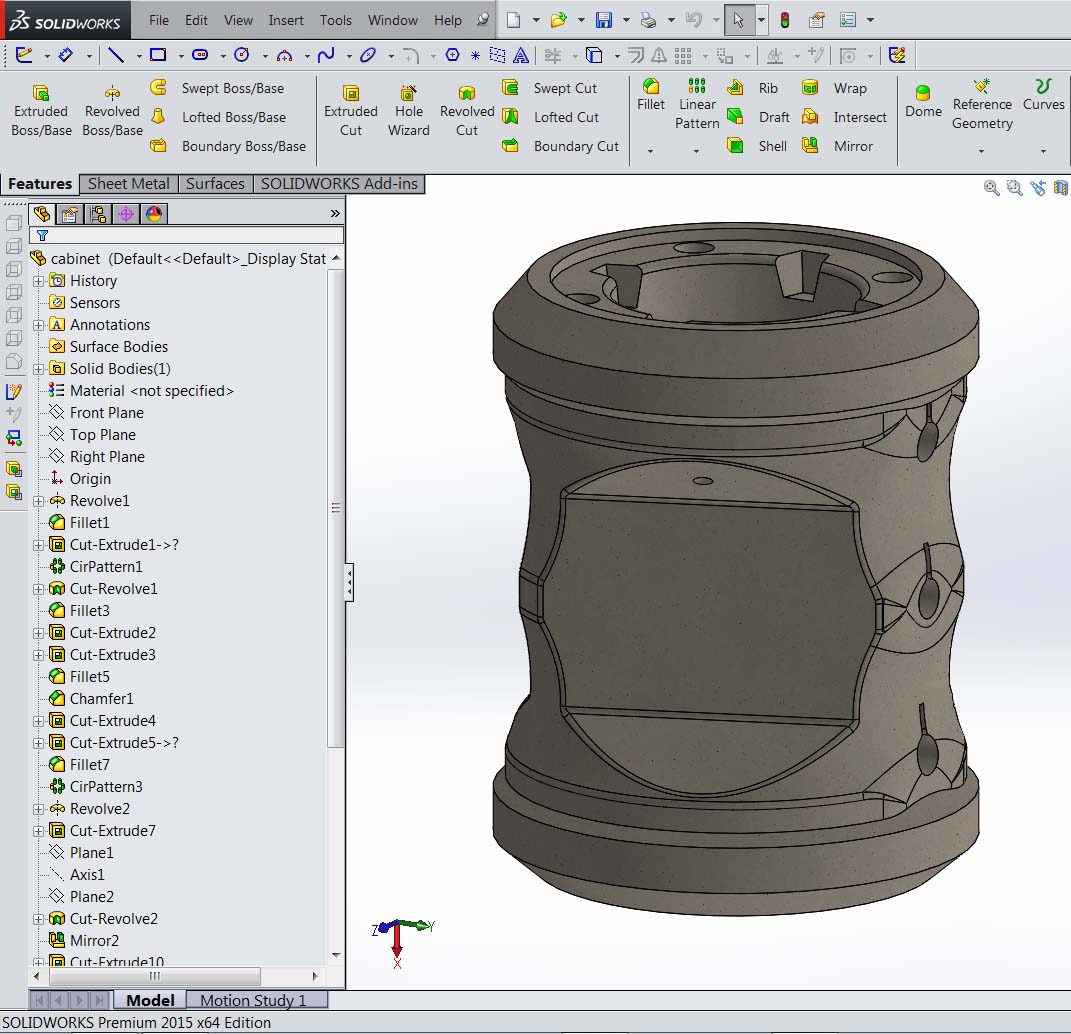
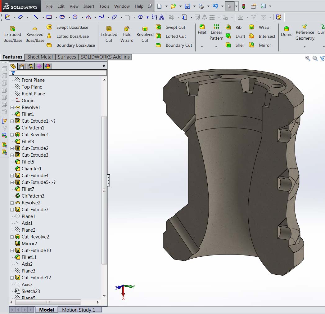
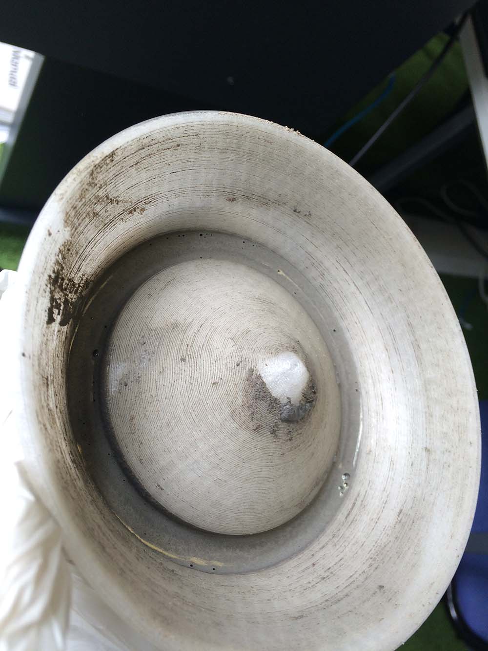
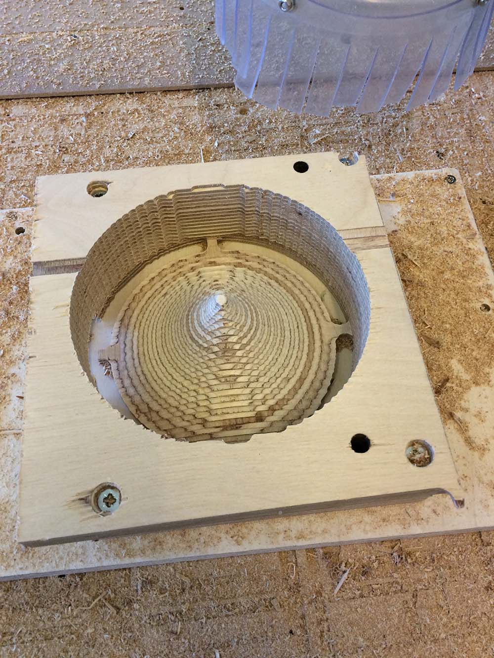
In the pictures above, it can be seen that the cabinet, have a parable-shape on the inside. I have not optimized the shape, but I know that potentially I could get better sound by doing that. It can also be seen that there are some holes all the way through, these holes are for wiring the speaker and the boards later on. The three holes that are not alway through are for fasten the plywood cover. After designing the cabinet, I made a mold, I did that by importing the cabinet-body into another part so I can work with the files separately. If I make any changes to the cabinet it will automatic update in the mold part. I use the shell feature and add some other features to optimize the part for 3d-printing and to make it easier to pour concrete into it.
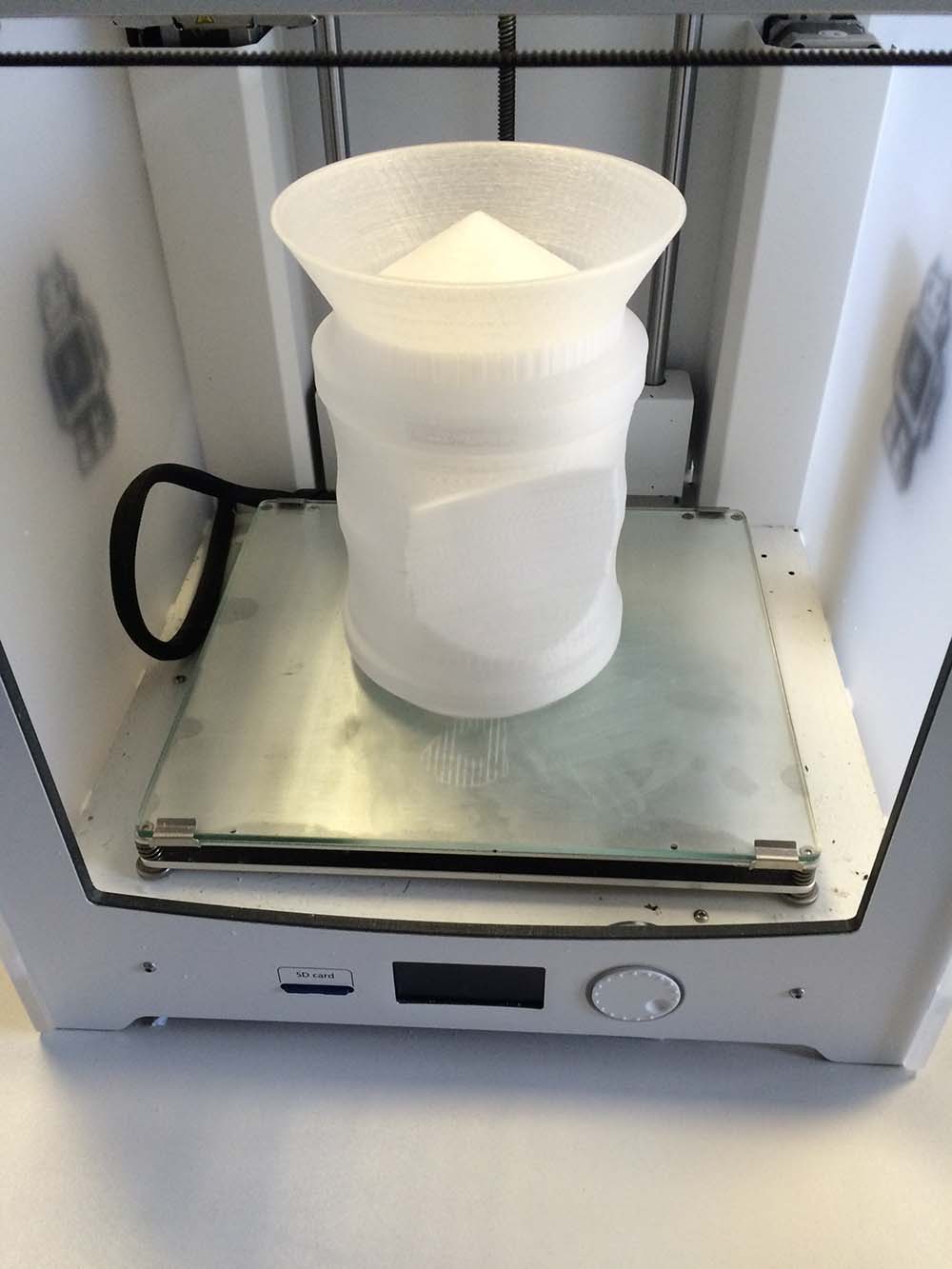
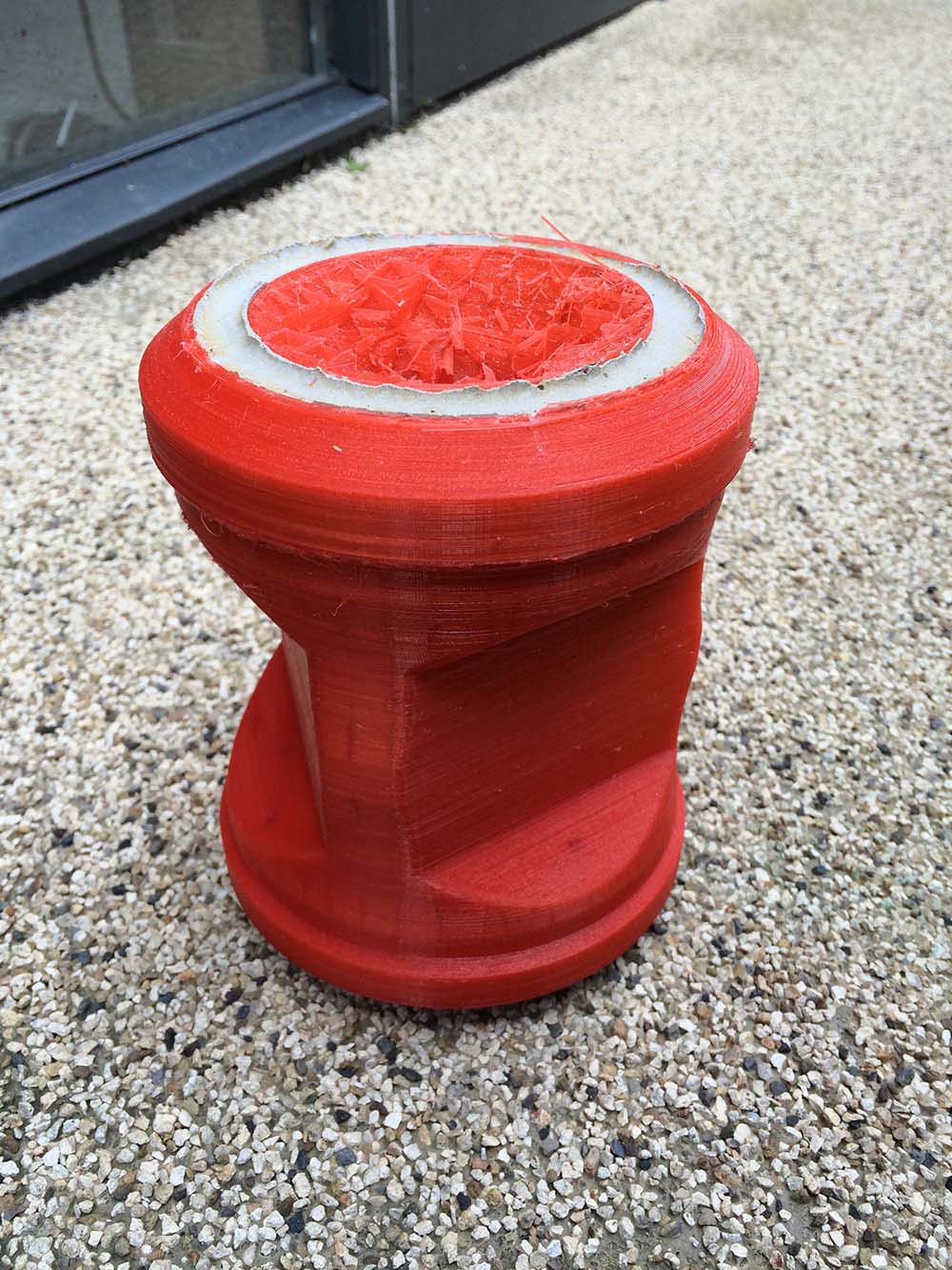
The mold is a 24 hours print, and I had a lot of trouble with the ultimaker to get a good print(the print on the picture above, is not the final design, i made a change to it and printed it again. It can be seen future down). the stl. file for the mold can be found in the package future down on this page.
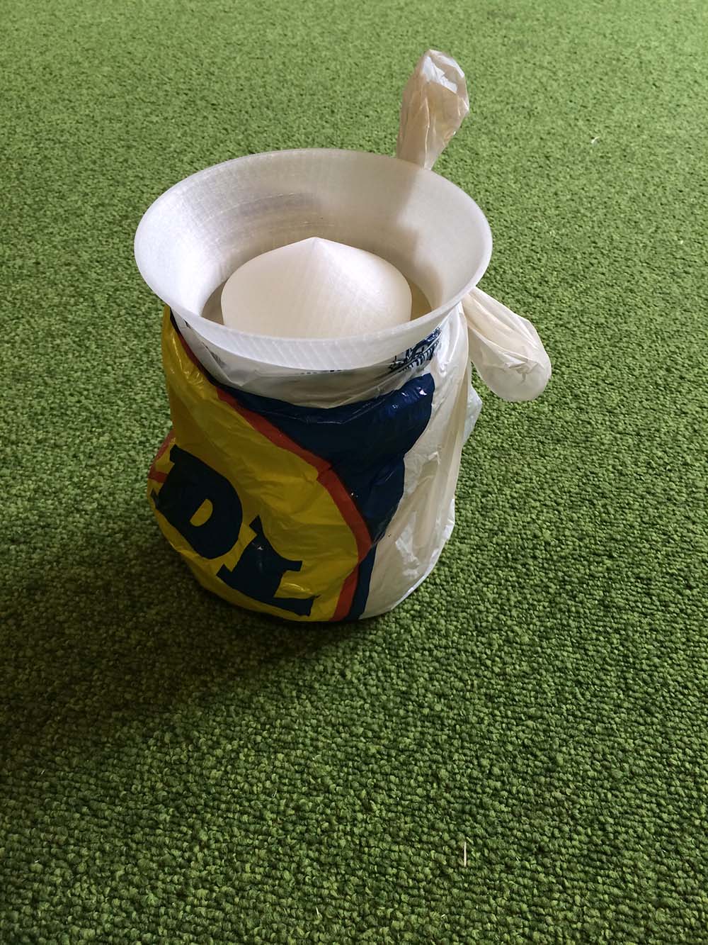
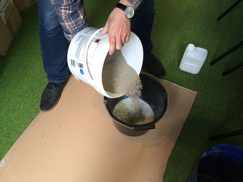
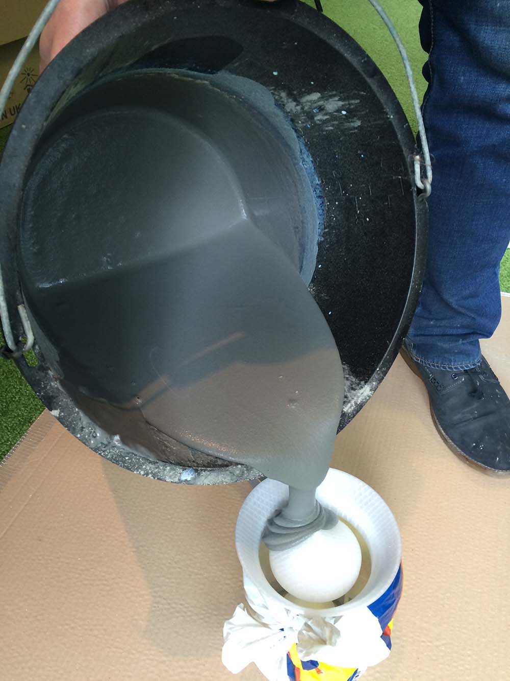
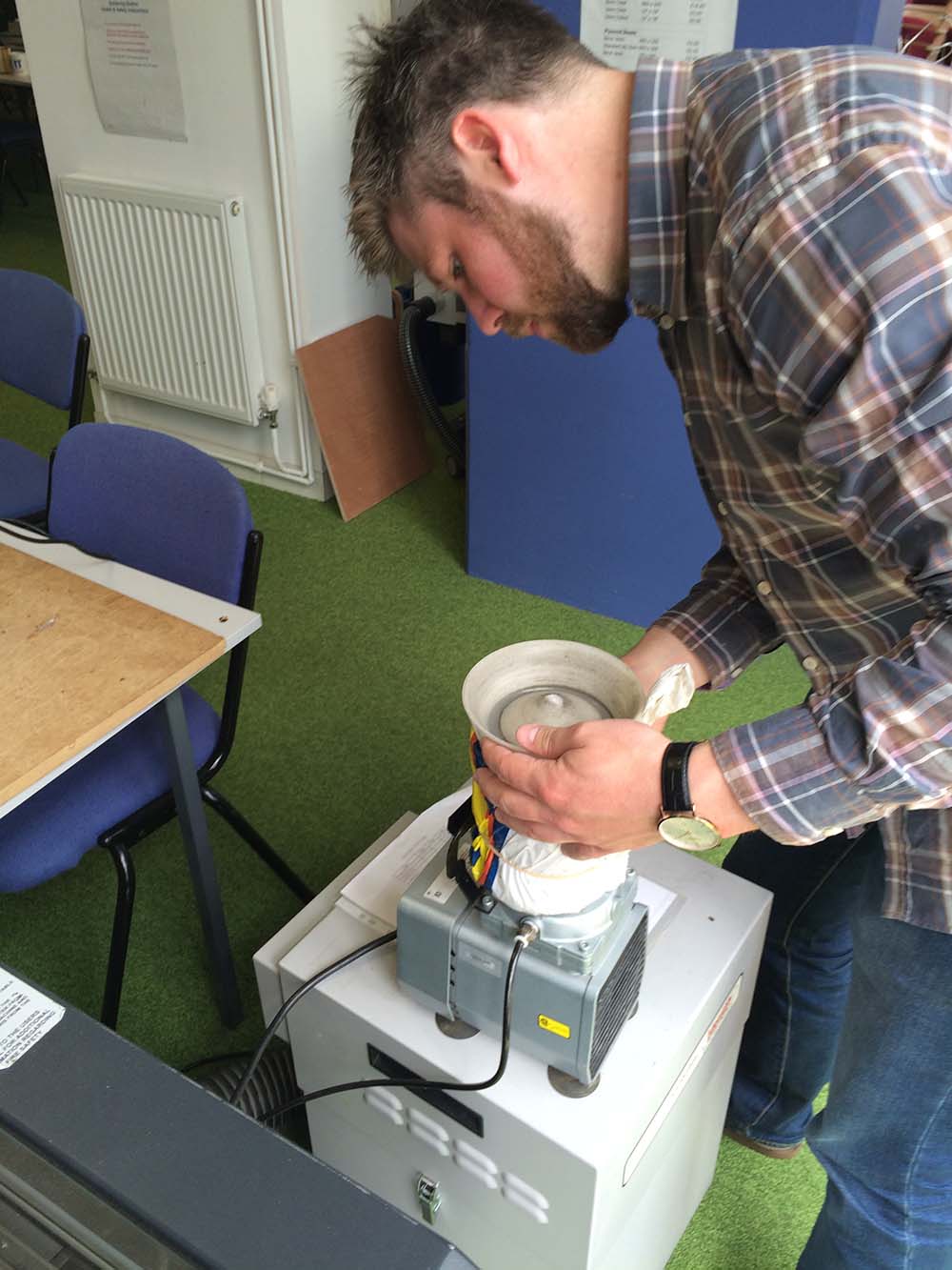
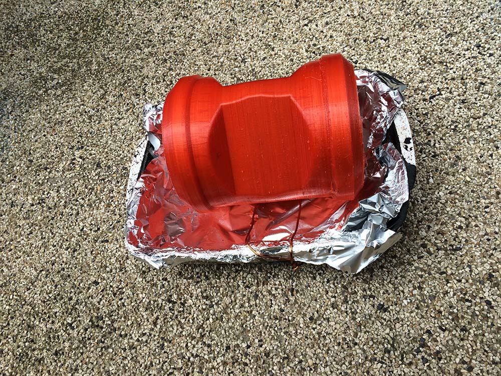
When the mold is printed, it is time to cast cabinet. I use floor-leveller concrete. In the series of pictures below the casting process can be seen. I have wrapped the mold in a plastic-back to make sure that the concrete does not leak. I am mixing a sall amount of concrete, I have estimated the volume of the cabinet in solidworks, so I do not mix fare to much concrete. One of design features I have added to the mold, is the litlle cone in the top. The cone makes it easy to pour concrete into the mold. I am vibrating the mold to get rid of air bobbles. The mold have to be totally dry before heating it up to 200 degrease, else it will crack. My mold was drying for 14 days.
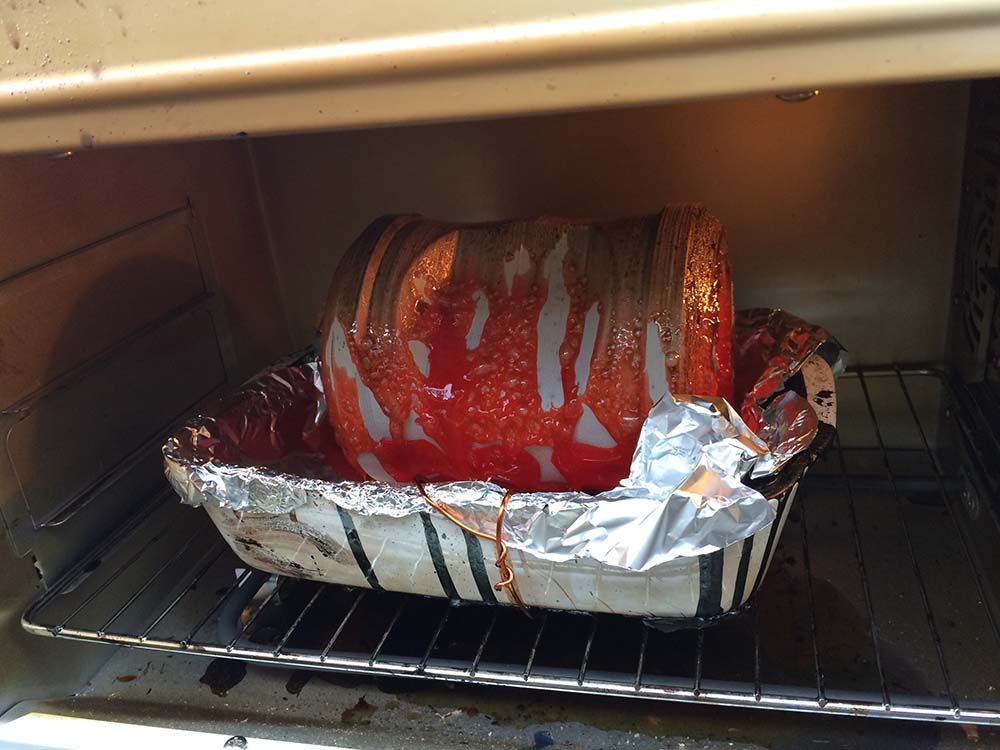
Next step is to melt the plastic of the concrete. I do that in a normal owen on 250 degrease. As it can be seen on the picture below and on the final cabinet, there are some colouring of the concrete. I think that is because the heat is to high. Maybe 200 would be better, it seams like some oil is dissolving from the pla at 250 degrease. It took 3 hours.
The cone
The cone have two functions, one is to propagating the sound, the other is to enclosure the touch-interface. The cone is milled on the shopbot. I made the setup for the shopbot in solidworks, where I added some taps to hold the cone. The cone is going to be milled from two sides. I glued three pieces of 18mm plywood together so I had a 54mm thick block(the cone is 50mm). The milling-program was generated in 3d-pathworks.
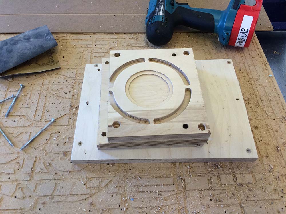
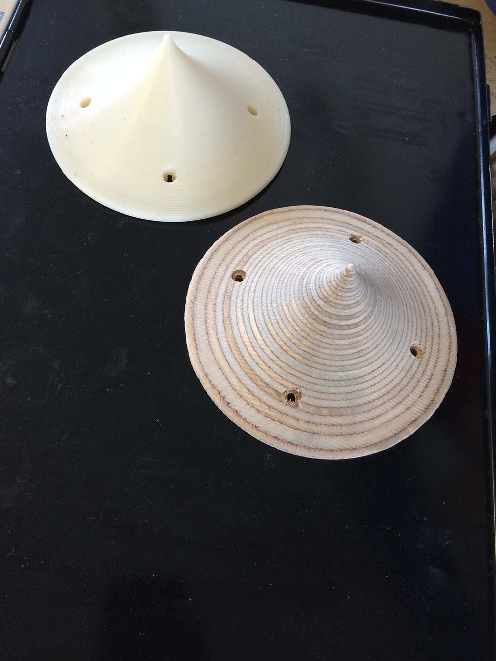
I like the plywood look for the cone, but the finish the shopbot delivered was not impressive. a lower stepover setting would properly help. I had to do a lot of sanding to get a nice surface.
Lasercut Parts
There is three lasercut parts in the speaker design. A fixture for the speaker, a plate in the top for the interface and the cover. The most complicated part is the cover because of the living hinge. I have made a lot of test to get to the "best" living-hinge, some of my tests and thoughts can be seen in "computer controlled cutting" where a describe some of the important parameters. All the parts are made in solidworks, to make a lasercut layout for living hinges it is important to do the hinge in a separate sketch there can be exported as an dxf. The parts can be downloaded here.
Fixtures
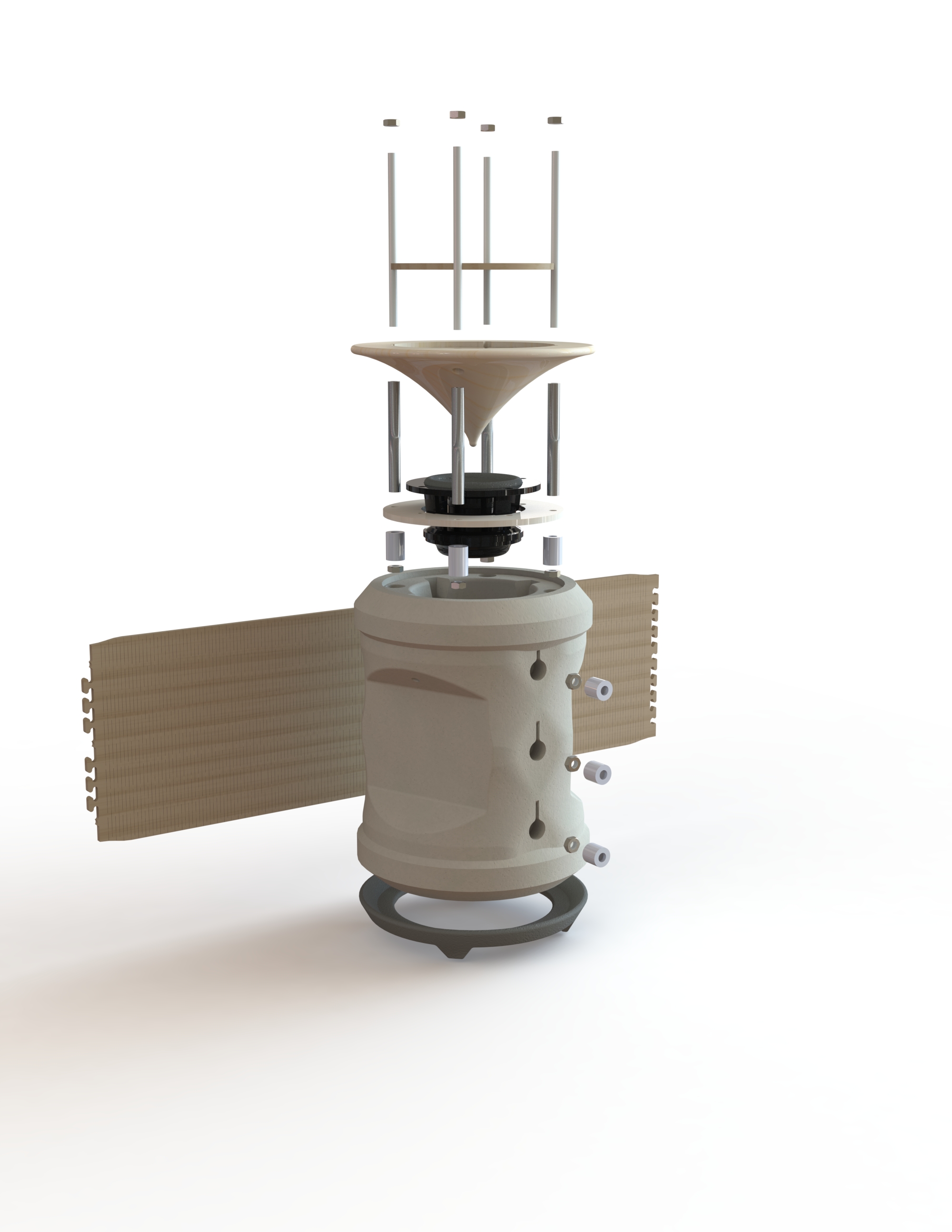
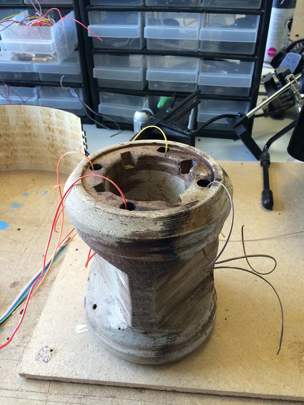
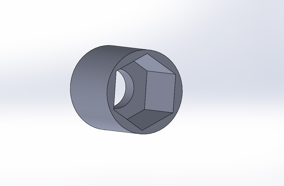
To keep all the parts in place, I had to fixture them. Because I could not just screw a bolt into the concrete, I had to come up with a solution. I design a kind of wall plug, that I could put a m4-nut into and then glue it into the concrete. Of coarse the plugs where 3d-printable.
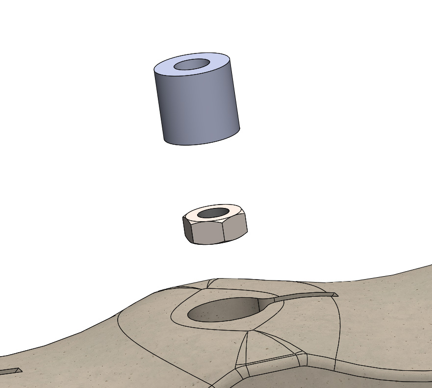
In the picture below, it can be seen how the plugs allow me to solder a wire to the m4-nuts and drag it through the hole to the electronics before glueing.
Besides 11 x m4-nuts, I have also used
3 x m4-bolts,
4 x 7cm alu-tubes(D:6mm d:4mm) and
4 x 10cm m4-threaded rods, in the design.
The Speaker
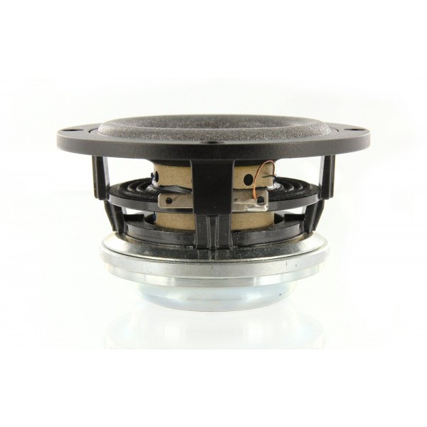
If I had the time, it could be nice to make the speaker on my self, but doing so would leave me with no time to do other stuff. Therefore I have chosen to buy a speaker. The speaker I have chosen, is a full-tone 2inch 20W speaker from the danish company
Scanspeak.
Class-D Amplifier
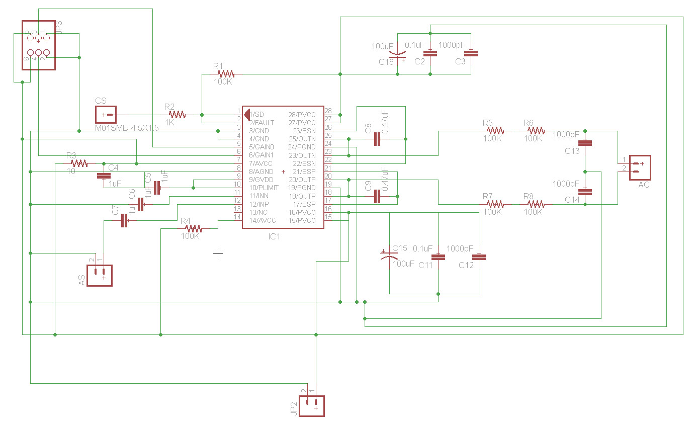
when I began to explore different types of amplifiers my head were blown off! There was so many different kinds. I have always thought that an amplifier was just an amplifier, I was wrong!! I have spend many, many, many hours reading about pros and cons of each kind. I ended up choosing a class-D amplifier, because it have a really high efficiency, so it does not need a big heat-sink to get rid of the heat. In my speaker design, I do not have a lot of space to big amplifiers so the first criteria for the amplifier was that it could fit. A class-D amplifier takes the analogue signal and turns it into electrical pulses which takes far less energy to amplify. All this happens in a little chip. In fact these chips are so small that it is nearly impossible to solder them. I found one chip that I thought I could solder, the tpa3111d1 . from texas instruments. I used the recommended-use schematic from the data-sheet as my starting point. there are some "filters" before the chip and before the output in the schematic. These filters are important because they smoothes the sound-signal. In the schematic these filters are defined as big resistors, but as seen in the picture to the right below, they are big inductors and ferrit-beads.
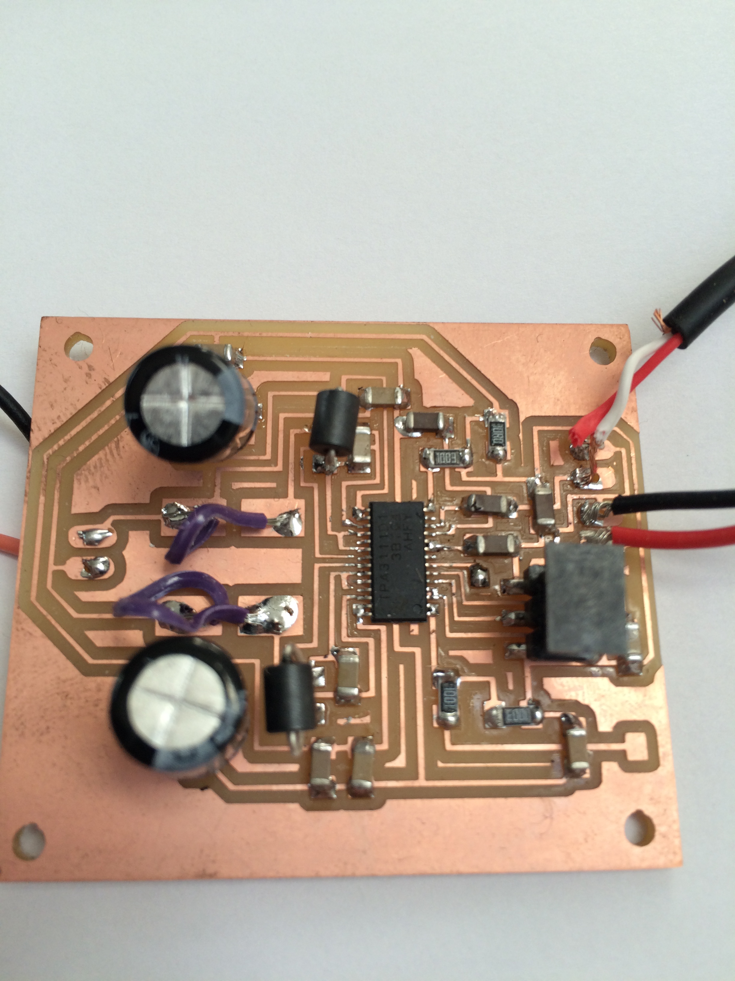
As I said before the small amplifier chips are really small. Therefore they are difficult to solder, but also to mill. If you want to use my board design, you might have to remove some pixels so the mill-bit can get in between the chips traces, it depends on which bit you are using.
When I was done with the board I made a simple test to see if it worked. I did that by connecting a little speaker and a 9v battery. Crossed my fingers and tried to play some music from my iphone. It did not work:( I was under alot of time pressure at that moment so I choose to focus on other stuff there was needed and use an of-the-shelf amplifier I had in back-up. I am positive that the problem is to be found in the soldering. The pins where really small, and I used a layout I was positive would work.
Volume Control
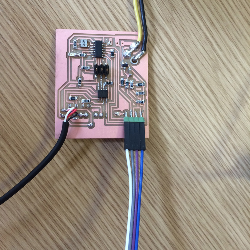
The other board in my design, is a board for volume control. The board is a bit complicated containing two chips and a lot of inputs and outputs. The board is build up around a attiny-44 which tells the other chip, a digital-potentiometer at what level the sound should be. There are 4 inputs or sensors; up, down, mute and a reference. The sensors are simple captive sensors made from copper-tape. When one sensor + the reference is touched it sends a signal to the attiny which sends a message to the digital pot what to do with the sound level. The digital potentiometer, is in fact just a resistant that can be changed digital. So by changing the resistance to a high level the sound signal will have difficulties to get through and there for the sound output will be lower than the input. So by changing the resistance in the pot, I can control the volume of my speaker.
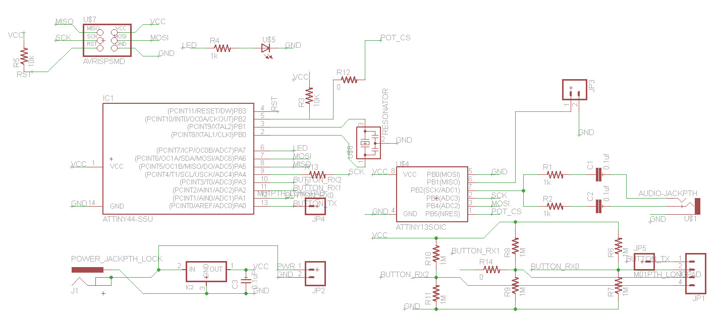
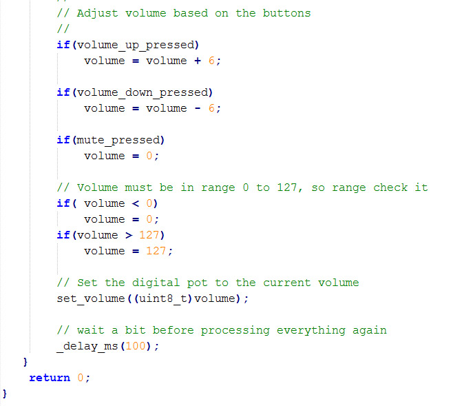
It would be easy for me to say that the program for the board is simple. But it is not, I got a lot of help from James Fletcher, last year student from Manchester. James is simply a genius. I would have been impossible for me to figure out how the attiny should communicate with the pot-meter on my own. So a big thanks to James!! Besides the communication the code is in fact simple. In the picture below, the "important" part of the code can be seen, there a a series of "if" functions, so depending on which sensor is pushed the program does different tasks. The volume is defined as an interval from 0 to 127. When a sensor is touched the value goes 6 up or down, or to 0 if it is mute. the volume can not be below 0 and not ower 127. There are a little delay in the end. I have optimized the value the volume is adjusted by, to 6. if I increase the value, the volume will go up faster when the volume up sensor is touched, and the other way around if I decrease it. I can also change the delay to do the same thing. a bigger delay will slow down the process, a smaller delay will speed it up. All the programming stuff can be downloaded here.
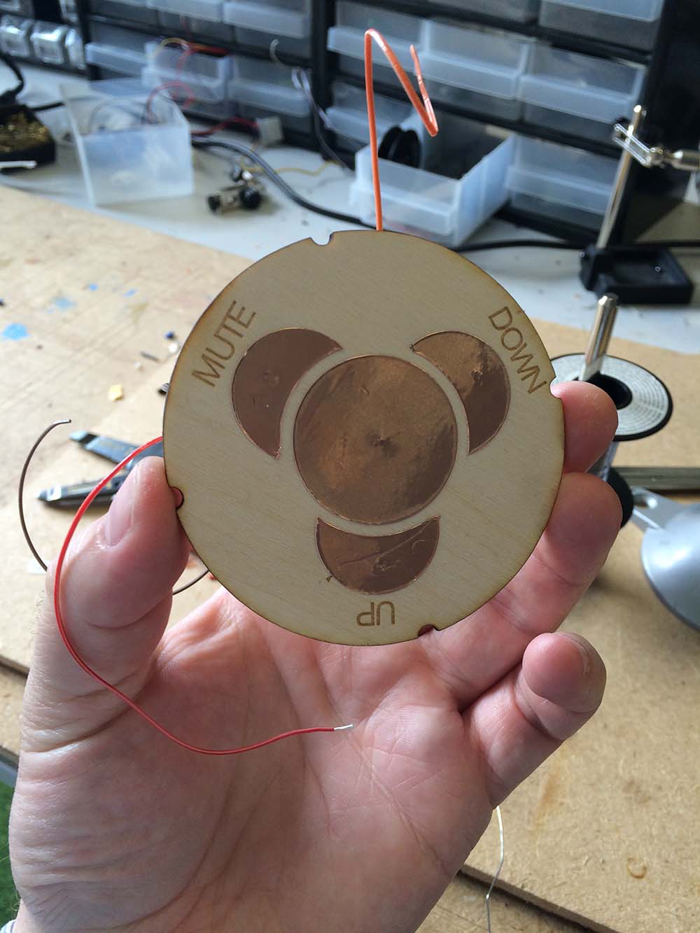
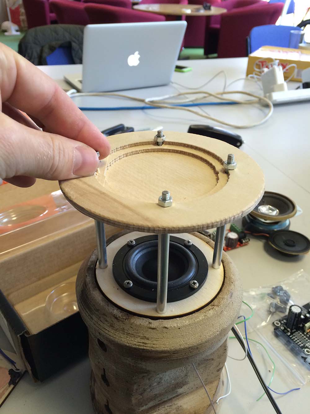
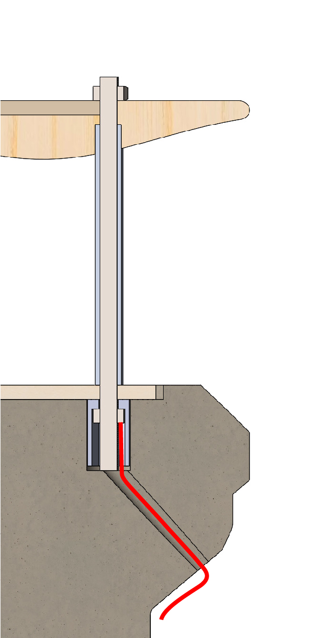
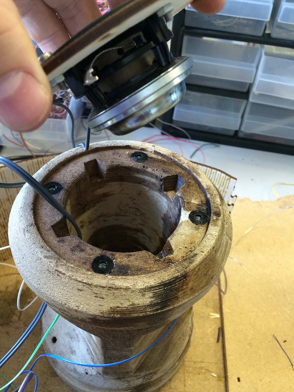
The sensors are connected to the board by a 1x4 pin header. the wires goes from the pinheaders around the cabinet through the holes up to the nut there are connected to the threaded rods. In the top of the speaker the rods are connected to the copper vinyl with a little wire running beneath the lasercute plywood-plate. The layout for the copper pattern can be downloaded here.
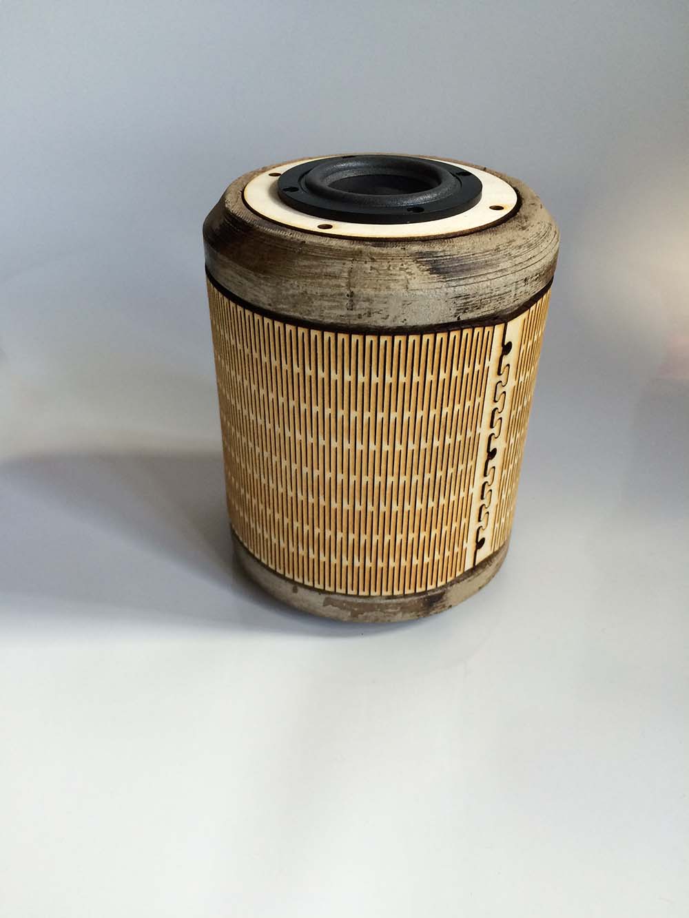
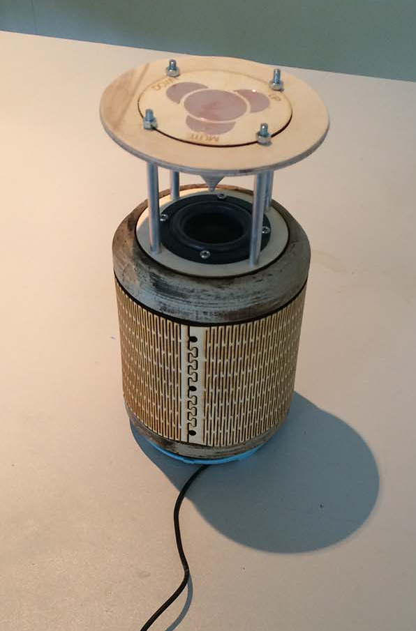
The Final Speaker
Even that I could not get my own amplifier to work, I am very satisfied with the result. I tested the speaker with another amp, and I am sure that the concrete cabinet is a really good solution and it can deliver a great sound with the right amp. I had a lot difficulty to fit all the electronics in the speaker. but i dont think it is possible to make more space, so I would have to optimize the electronic boards. Next step could be to integrate bluetouth so a aux-stick not is necessary. And maybe a batteri in stead of a extern power-supply.
All theSolidworks and stl. files. can be found
here.
The layout for the boards can be downloaded
here.