
Computer-Controlled Cutting
This week's learning was to cut various material by laser and vinyl cutting, from vector graphics made in such programmes as illustrator,
inkscape and solidworks. I have used solidworks much this week,
as the program allows me to make a parametric structure of my designs
that make it easy to change the design by changing the parameters.
Designing a construction-kit
This week's task is to make a design kit that can be put together using some self- designed connection/joints.
The material we are working in is cardboard. Therefore, I have chosen to use simple pressure joints,
as they work well in the soft cardboard.
Testing
To design a functioning construction kit, it is necessary to find the best dimensions for compression fit assembly,
therefore I started to make a simple test. First I measured the thickness of the cardboard that was available, it was about 2.5 mm.
There after I drew in solidworks a simple sketch with 7 slots, in addition to testing a collection of 2.5mm joints,
I made three collections of larger dimensions, respectively 2.6 mm 2.7 mm , and 2.8mm,
and three smaller collections with dimensions of 2.4mm, 2.3mm and 2.2mm respectively.
The cut test design can be seen in the image below.
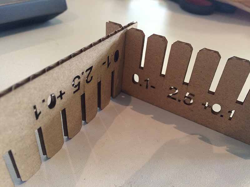
After trying the different sized joints, I came up with 2.2mm being the best compression fit.
I did not think it was necessary to do further tests with 2.1mm when the fit was quite comfortable at 2.2mm.
Here you can download the dxf or the solidworks file .
My idea
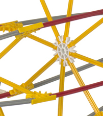
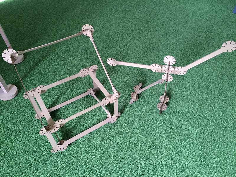
My idea is to make a Structural assembly resembling KNEX.
I played a lot with KNEX as a child and thought it was fantastic with all the endless opportunities afforded to by a toy.
There are many different assembly joints in a KNEX building set,
but there are some fundamental parts such as round plates and bars.
The plates and the bars can be clicked together to create large assemblies that can fasten easily.
The principle can be seen in the image below.
Designing in Solidworks
The reason I have chosen to use solidworks, is that the way in which sketches are easier to control than, for example in inkscape and illustrator.
It is also able to make a parametric setup that makes it easy to create large changes by changing a few parametric parameters.
Being able to make these changes is very time saving if you have to make several tests.
As I have already made a test of the joints , it should not be necessary , but you never know.
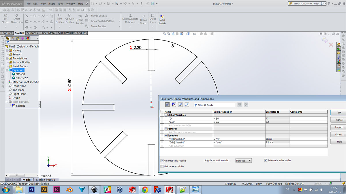
I always try to keep my sketches as simple as possible.
After extruding the sketch, you can apply chamfers and other details (which is very difficult in inkscape).
By keeping it simple, it is much easier to manage any changes that need to be made. I use .dxf format when I export from solidworks.
You can either choose a particular view, or a surface where you can export a contour from.
Below, you can see a picture of the finished kit.
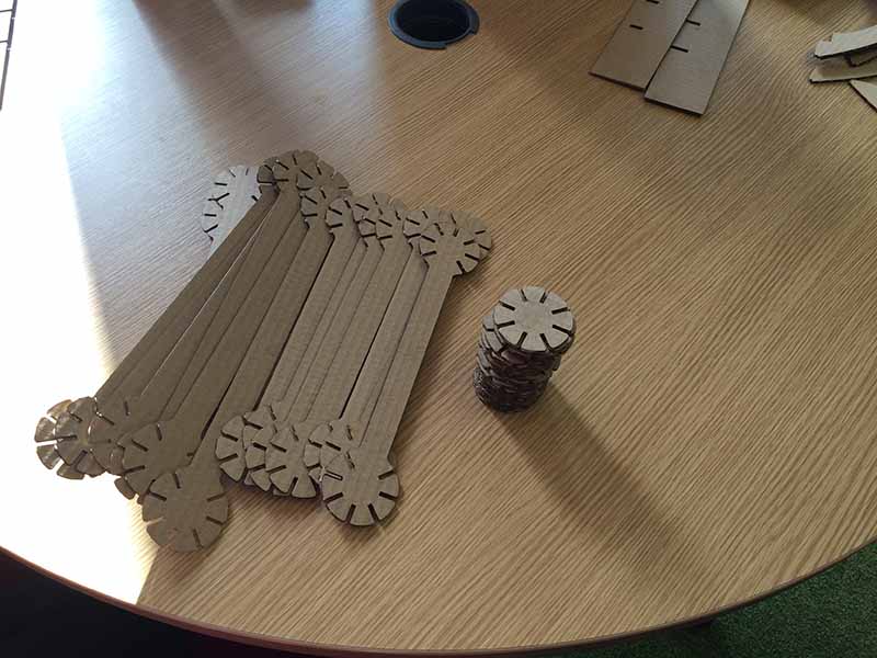
 Here you can find the dxf . layout or the solidworks file .