Many notes can also be read on this page of assignment no. 18.
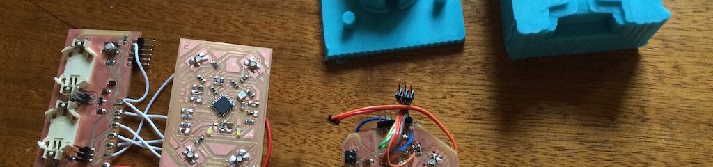
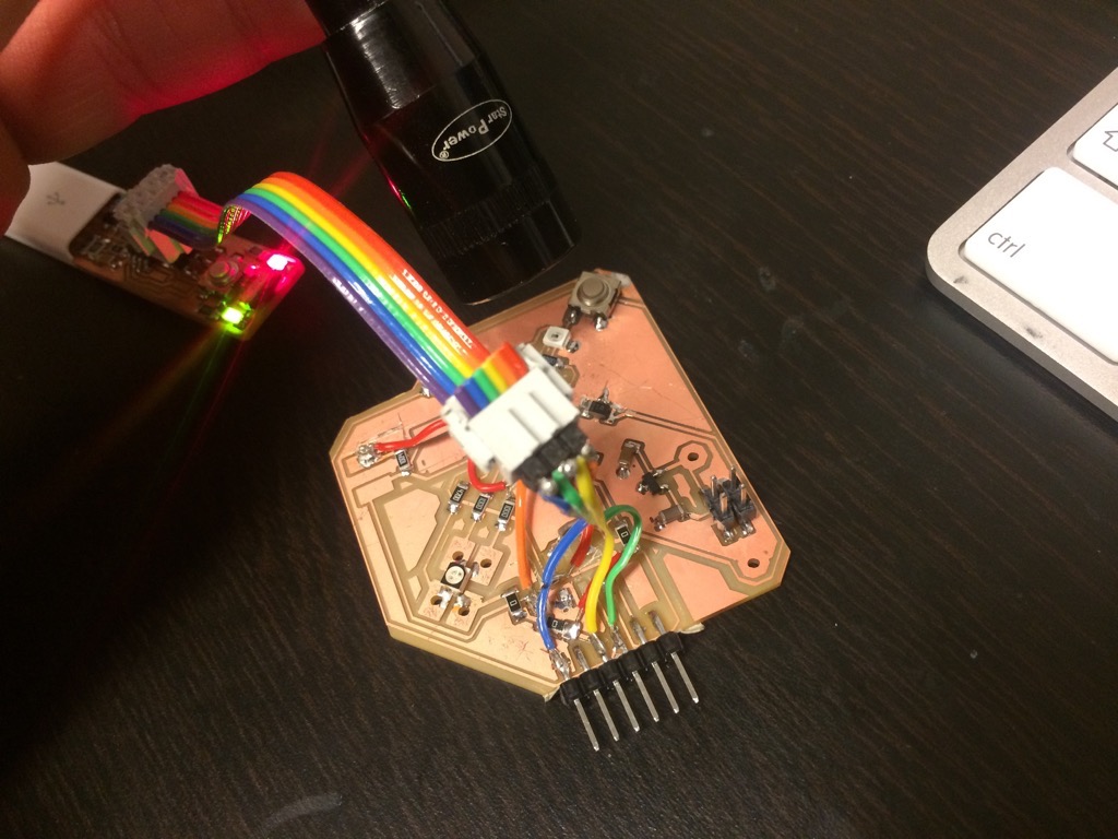
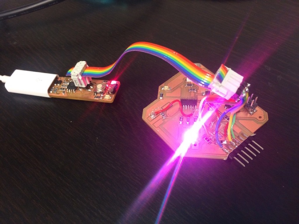
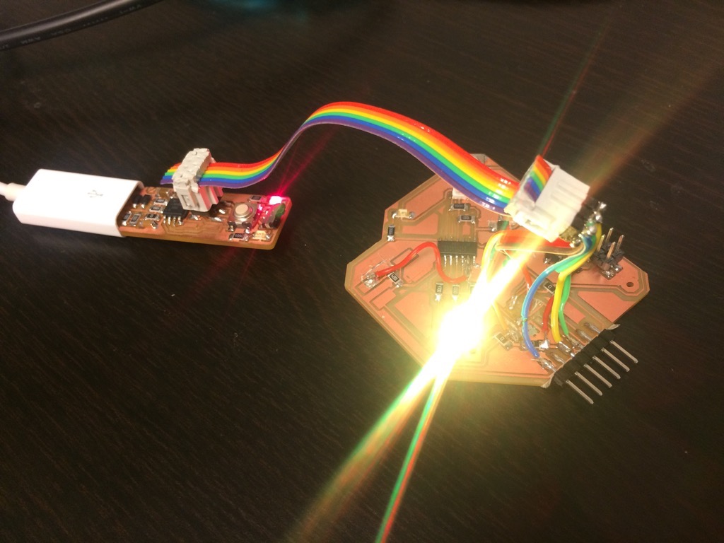
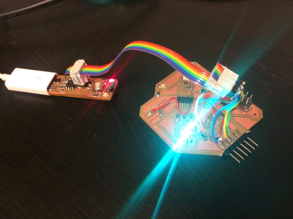
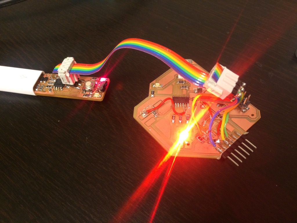
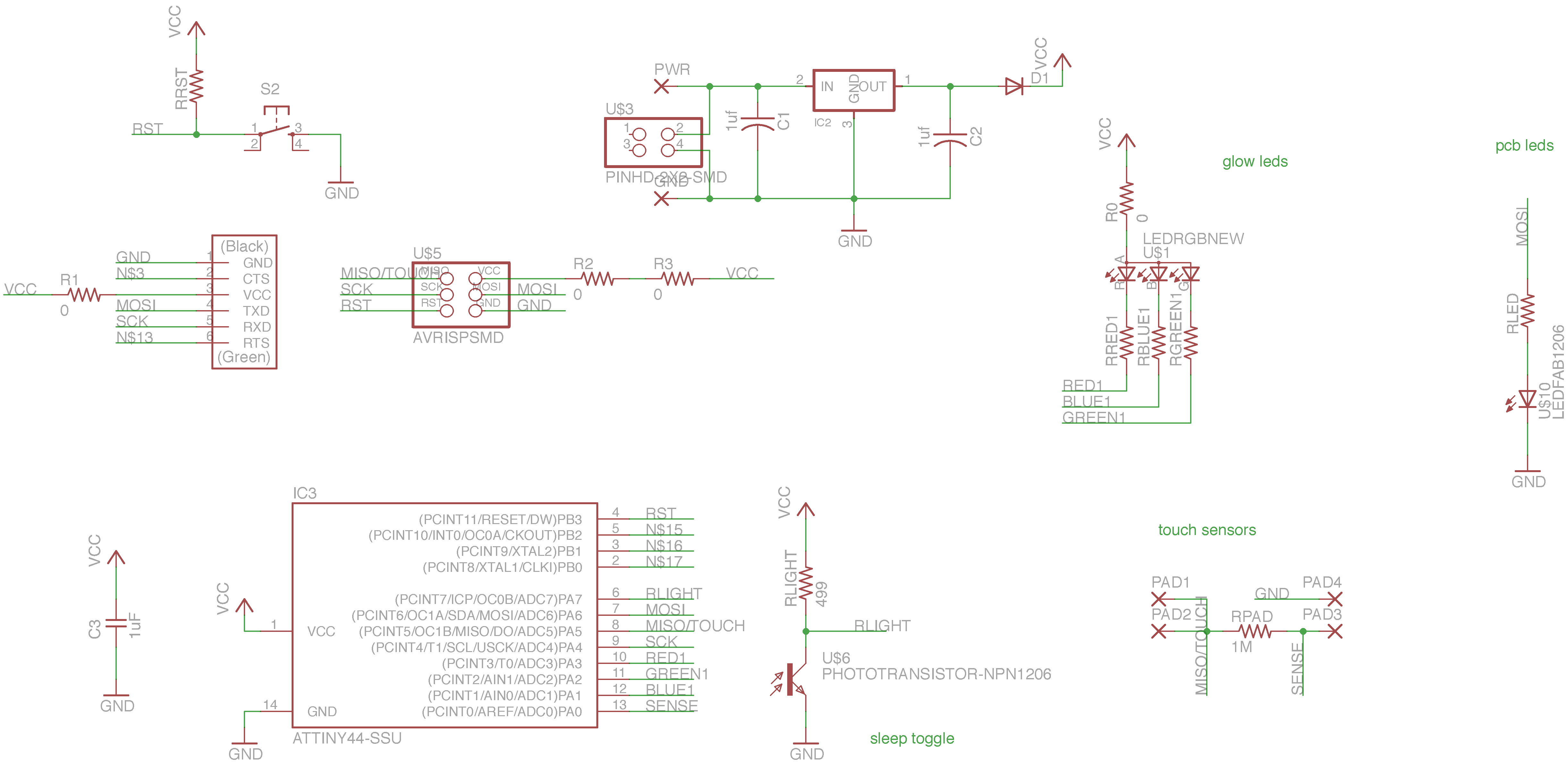
For prototyping purposes I first made a board 0.1 with only one rgb led and a light sensor (+ pins for touch sensor).

Board 0.1 files:
In Rhinoceros I created a box that I than carved with planes that I placed at angles. It took a while to figure out the right approach to get the look and feel I was looking for. It is a good idea to already have the tool in mind that you are going to use for milling the wax mold because that affects the design constraints. This is something I focused on very much during the Molding and casting assignment.
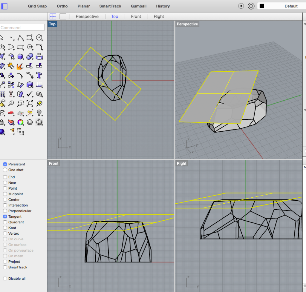
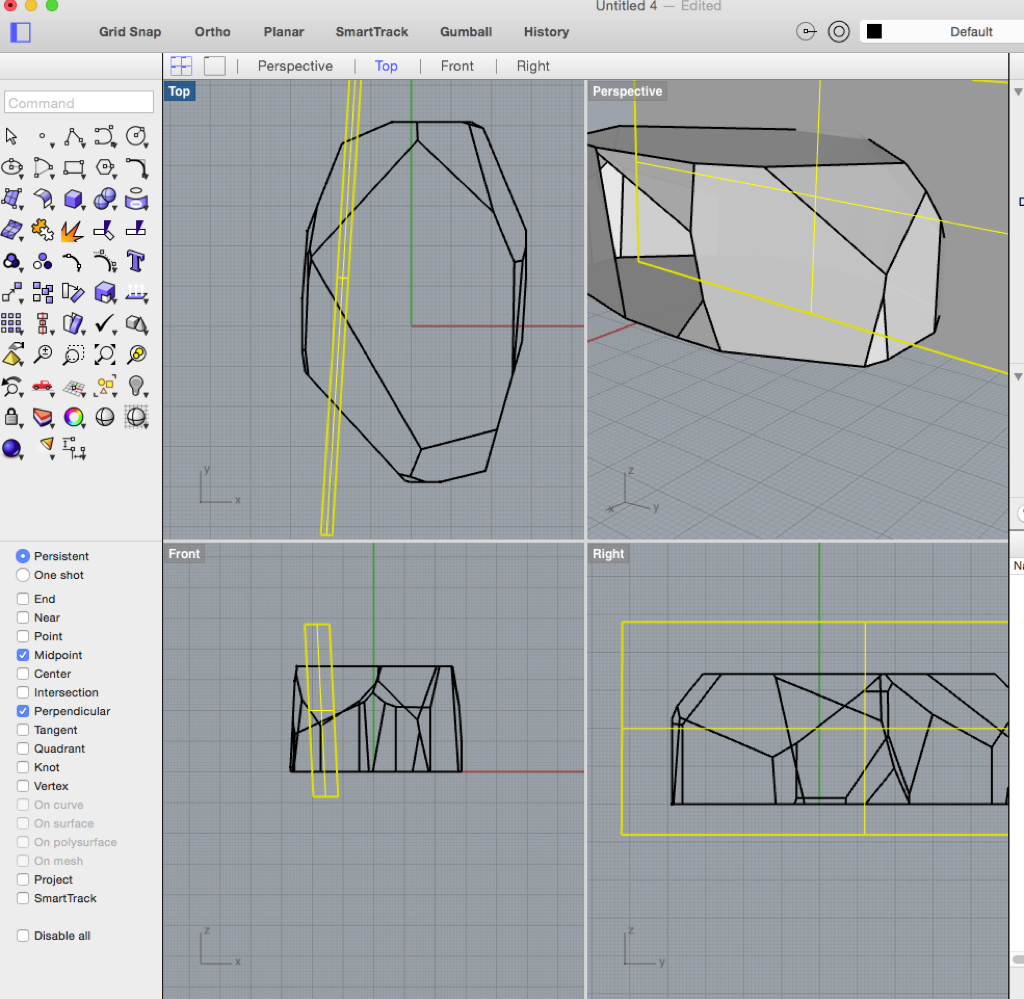
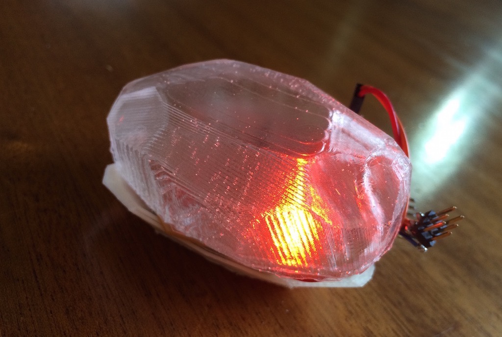
This is a 3D model of the crystal casing that I have cast:
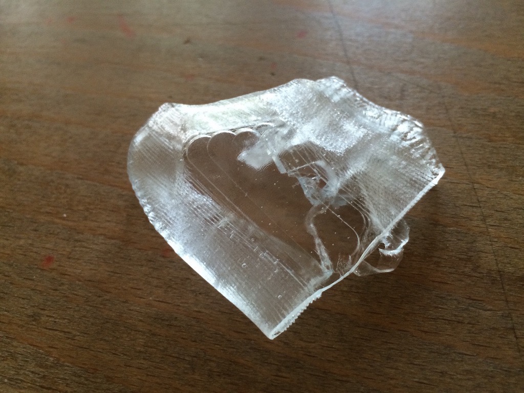
An important part of my design is the top part which I want to make out of clear resin. From Form X I got the Crystal Clear 202 resin. It is used for parts that need to be clear as glass which I want my design to be. This is because I want people to be able to look inside the object at the pcb board.
It has a curing time of 90 minutes which is great for my timing.
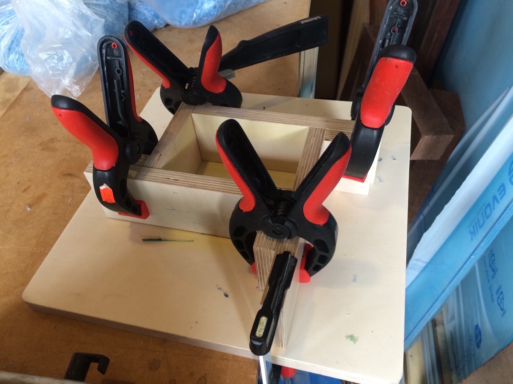
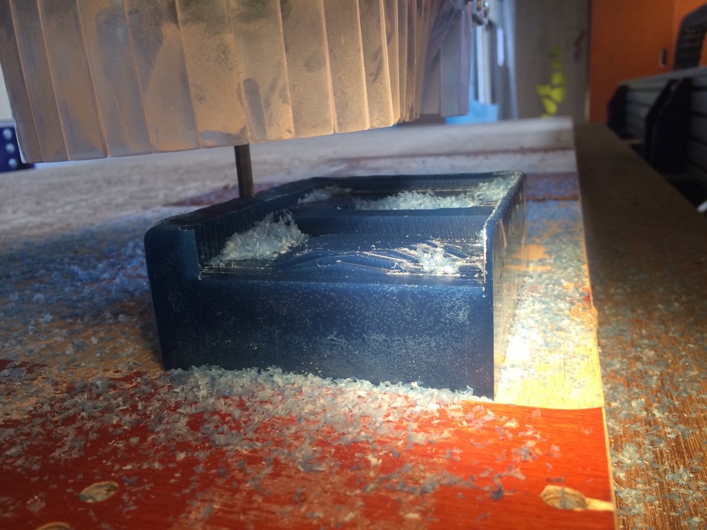
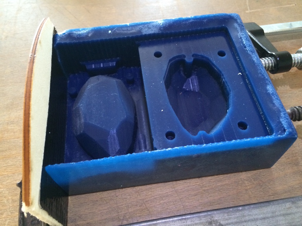
During milling I made a mistake in setting the x axis which caused the end mill to take out one edge of the mold. It was not a big problem, because the form itself was intact and also the keys. I was able to repair the mold with some wood that I covered with a bit of duct tape.
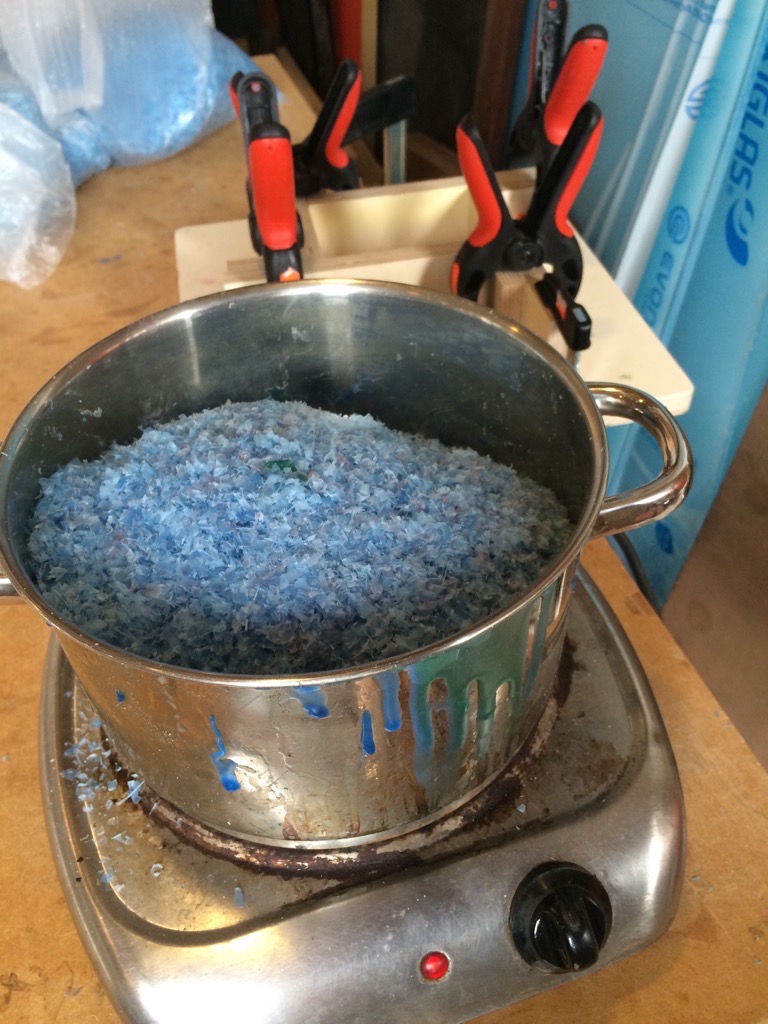
I had to recycle some used millable wax. With the wooden parts you can make a rectangle shape. I measured my 3D object and added approx. 1 cm additional space (to allow for keys and milling) on all sides which gave me the size I needed.
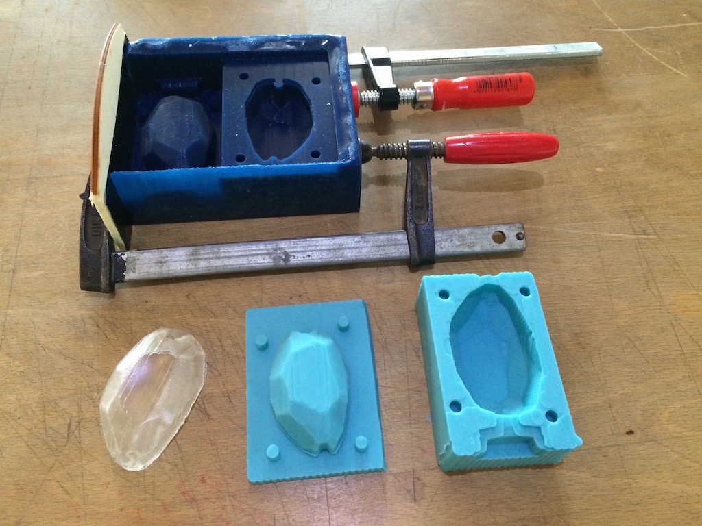
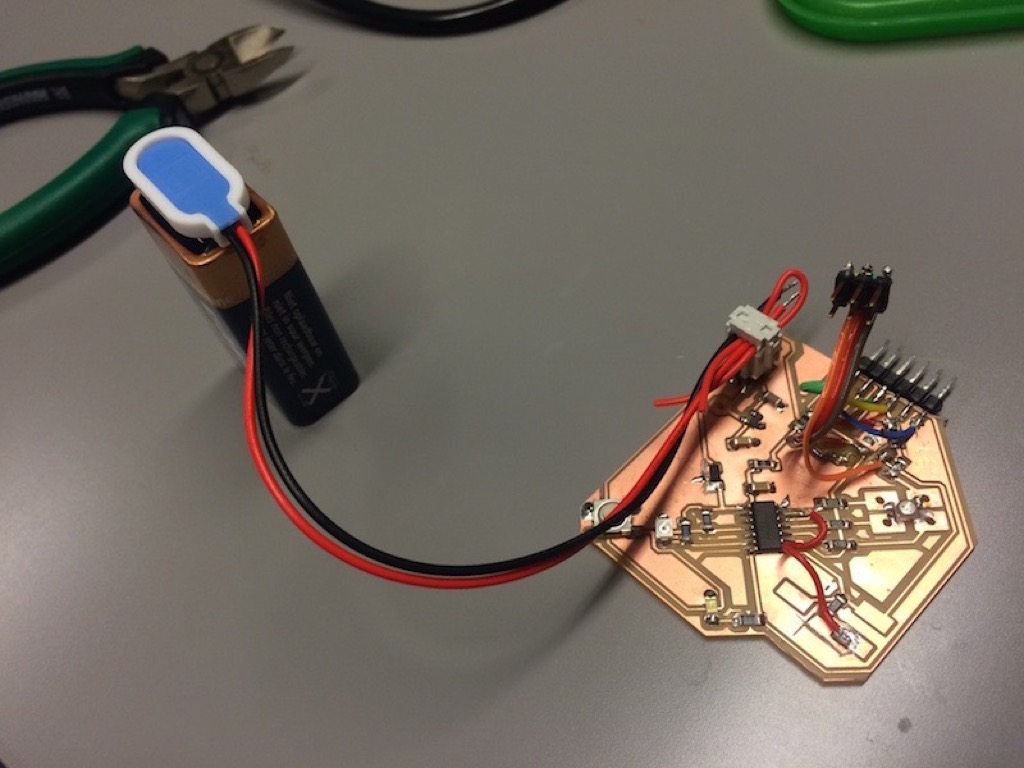
When the soft mold was ready after less than an hour (yay for fast-curing materials!) I wsa able to do my first casting. I was multitasking at this point, because I was also milling a board and working on code at the same time.
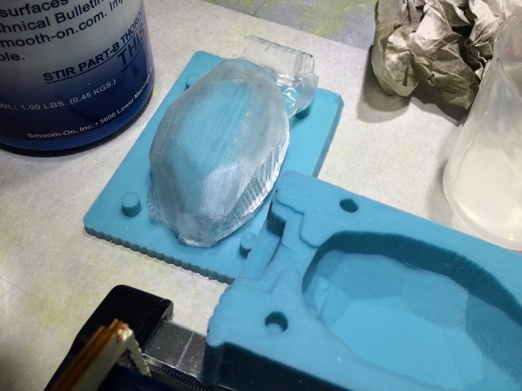
The two parts had to be mixed in a 100/90 weight ratio. The part does not need much material, so I only had to poor small amounts. Doing so directly from the canister proved a little unprecise.
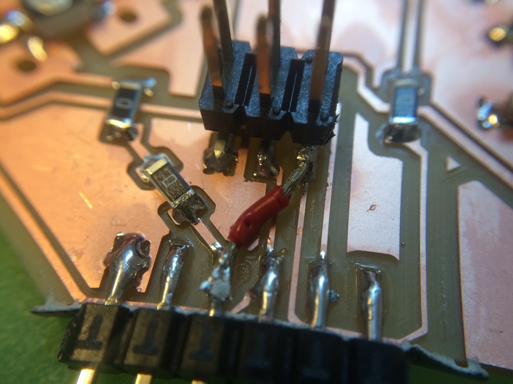
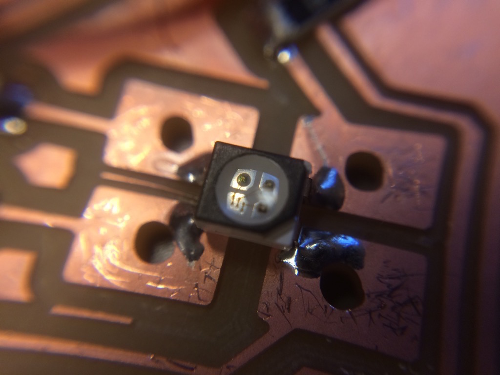
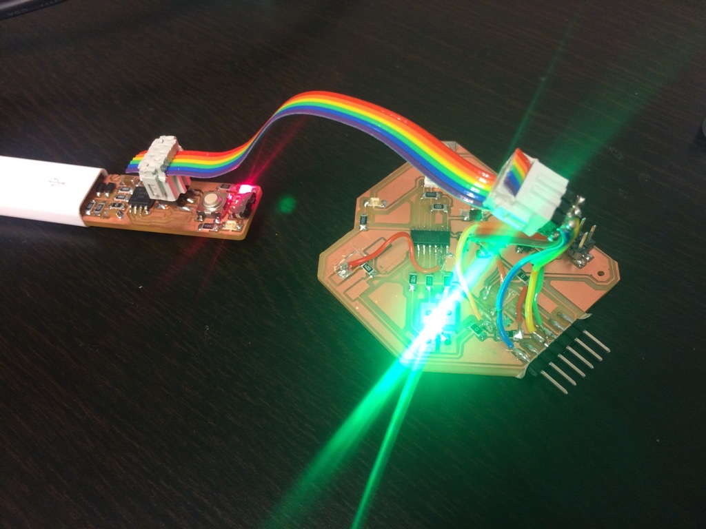
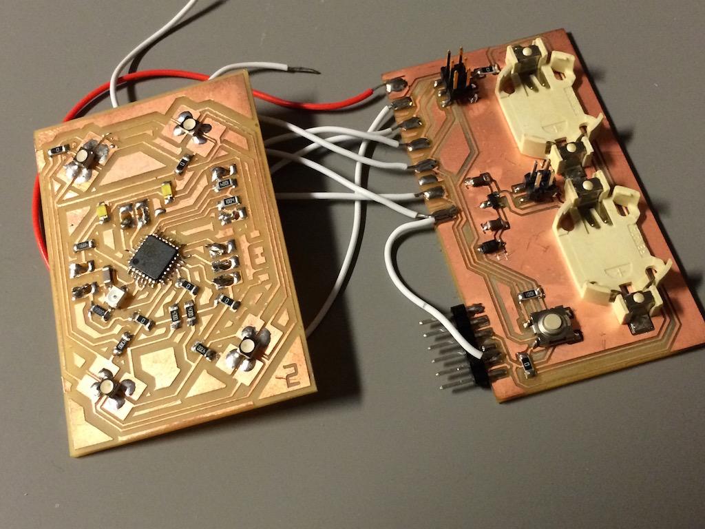
After soldering all the components onto the board, the RGB led was not working. After taking a closer look, i saw that the pin that I thought was the led's anode, was in fact another one. Hard to see. Luckily I have a Ollo clip lense for my camera that allows me to take macro shots.
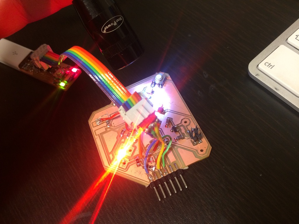
I started to experiment with code to adjust the color of the led. While I was coding, I tried to think ahead of possible future functionality I might want to include at some point. So I made it a habit to clearly comment all the code and also to keep the main loop as clean as possible by using functions for very specific operations. I gave functions and variables clear names that were also differently formatted. This improves readability of code.
I decided to use the light sensor at first to demonstrate how JEWL might work.
/// JEWL 0_1
//
/// tap lightsensor to toggle between primary and secondary colors

// Casper Koomen @ Fab Academy 2015

// serial only included for development and debugging
#include "SoftwareSerial.h"
SoftwareSerial mySerial (6, 4);

// setting lightsensor pin
int lightsensor = 7;
int lV = 0;
int threshold = 950;

// setting color pins
int red = 1;
int green = 2;
int blue = 3;

//set colorvalues
int max_value = 150;
int min_value = 0;

int rV = min_value; // where red starts
int gV = max_value; // where green starts
int bV = max_value; // where blue starts

int count = 1;

void setup()
{
  mySerial.begin(9600);

  pinMode (red, OUTPUT);
  pinMode (green, OUTPUT);
  pinMode (blue, OUTPUT);

  analogWrite (red, rV);
  analogWrite (green, gV);
  analogWrite (blue, bV);

  pinMode (lightsensor, INPUT);
}

void loop()
{
  lV = analogRead(lightsensor);

  mySerial.println(analogRead(lV));
  mySerial.println(count);

  if (lV > threshold)
  {
    toggleColor();
  }

  delay(250);
}

void toggleColor()
{
  switch (count) {
    case 1:
      count = 2;
      rV = min_value;
      gV = max_value;
      bV = max_value;
      break;
    case 2:
      count = 3;
      rV = min_value;
      gV = min_value;
      bV = max_value;
      break;
    case 3:
      count = 4;
      rV = max_value;
      gV = min_value;
      bV = max_value;
      break;
    case 4:
      count = 5;
      rV = max_value;
      gV = min_value;
      bV = min_value;
      break;
    case 5:
      count = 6;
      rV = max_value;
      gV = max_value;
      bV = min_value;
      break;
    case 6:
      count = 1;
      rV = min_value;
      gV = max_value;
      bV = min_value;
      break;

     default:
       break;
  }

    analogWrite (red, rV);
    analogWrite (green, gV);
    analogWrite (blue, bV);

  delay(500);
}
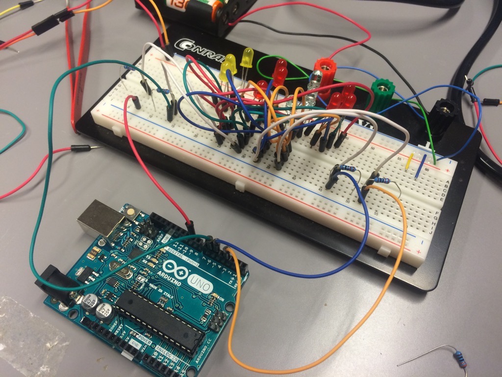
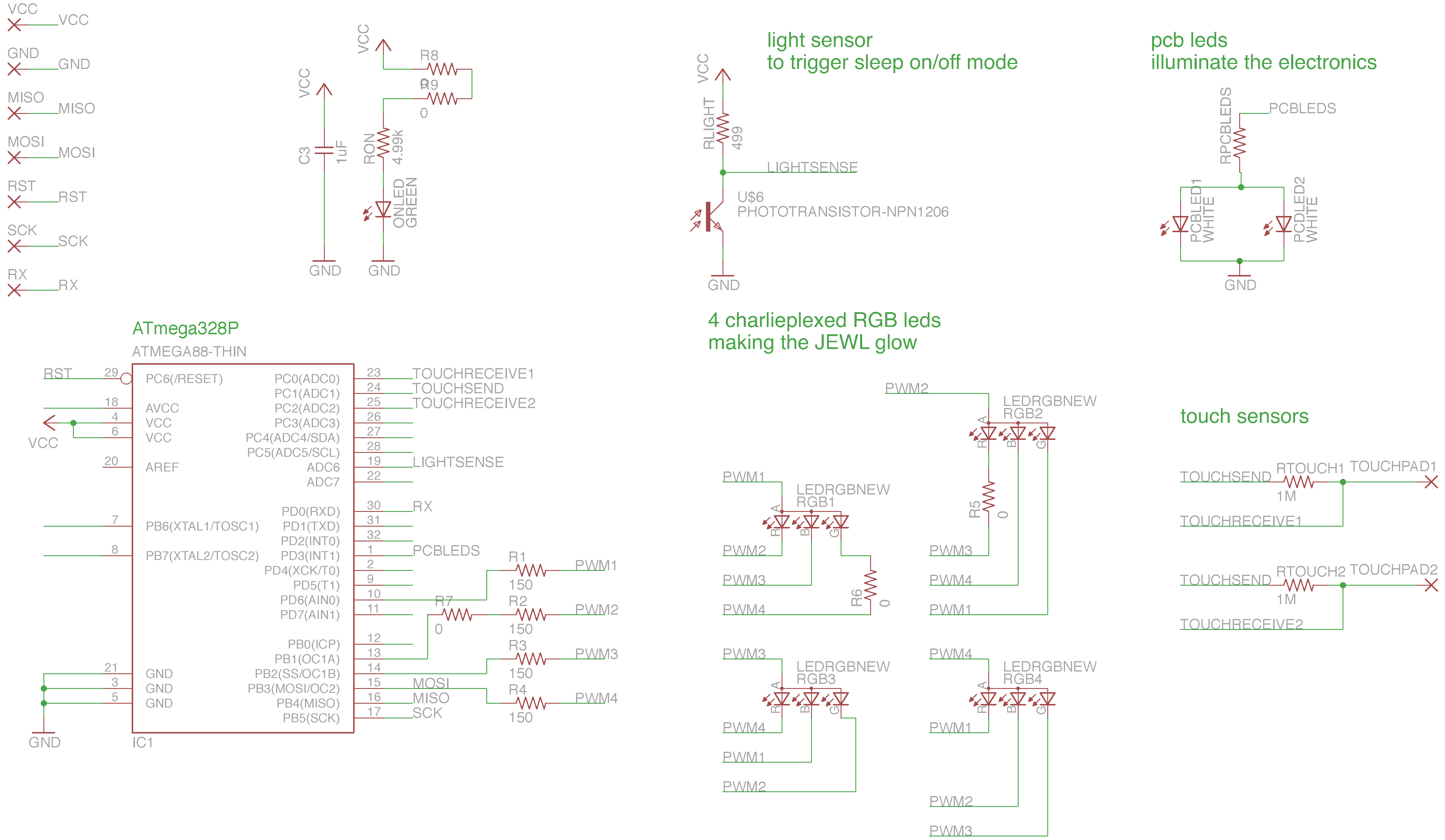
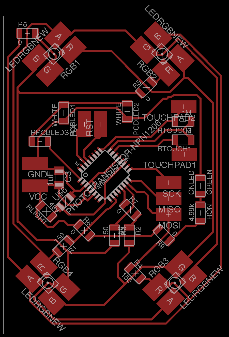
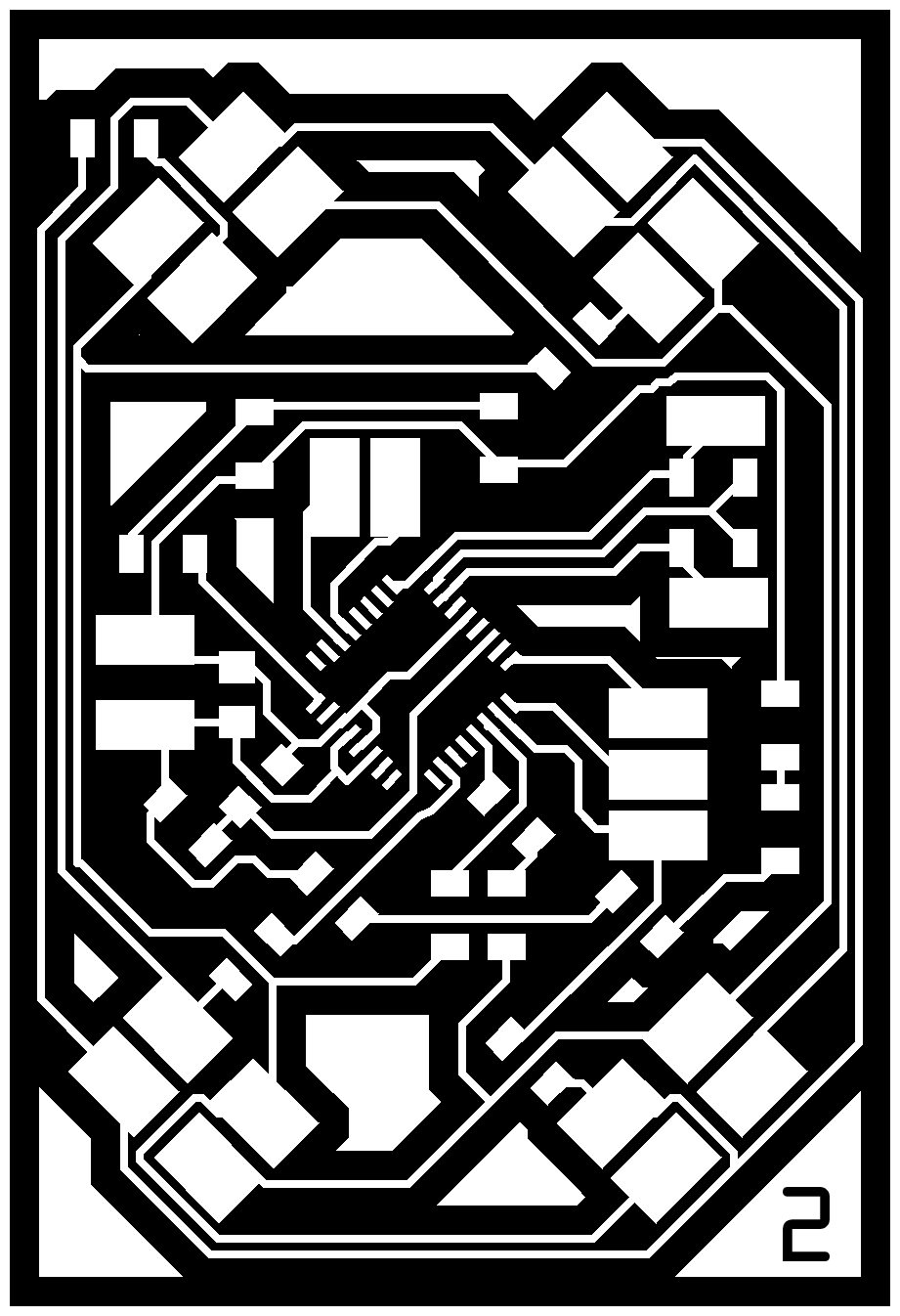
After I saw that board 0.1 was working well, I began to design board 0.2 which has 4 RGB leds in a charlieplex configuration. I found a schematic that helped me to figure out how to do this. However I was not sure that it would work with RGB leds with common anodes, so I decided to recreate the scenario on a breadboard just to get a sense of what I was making.
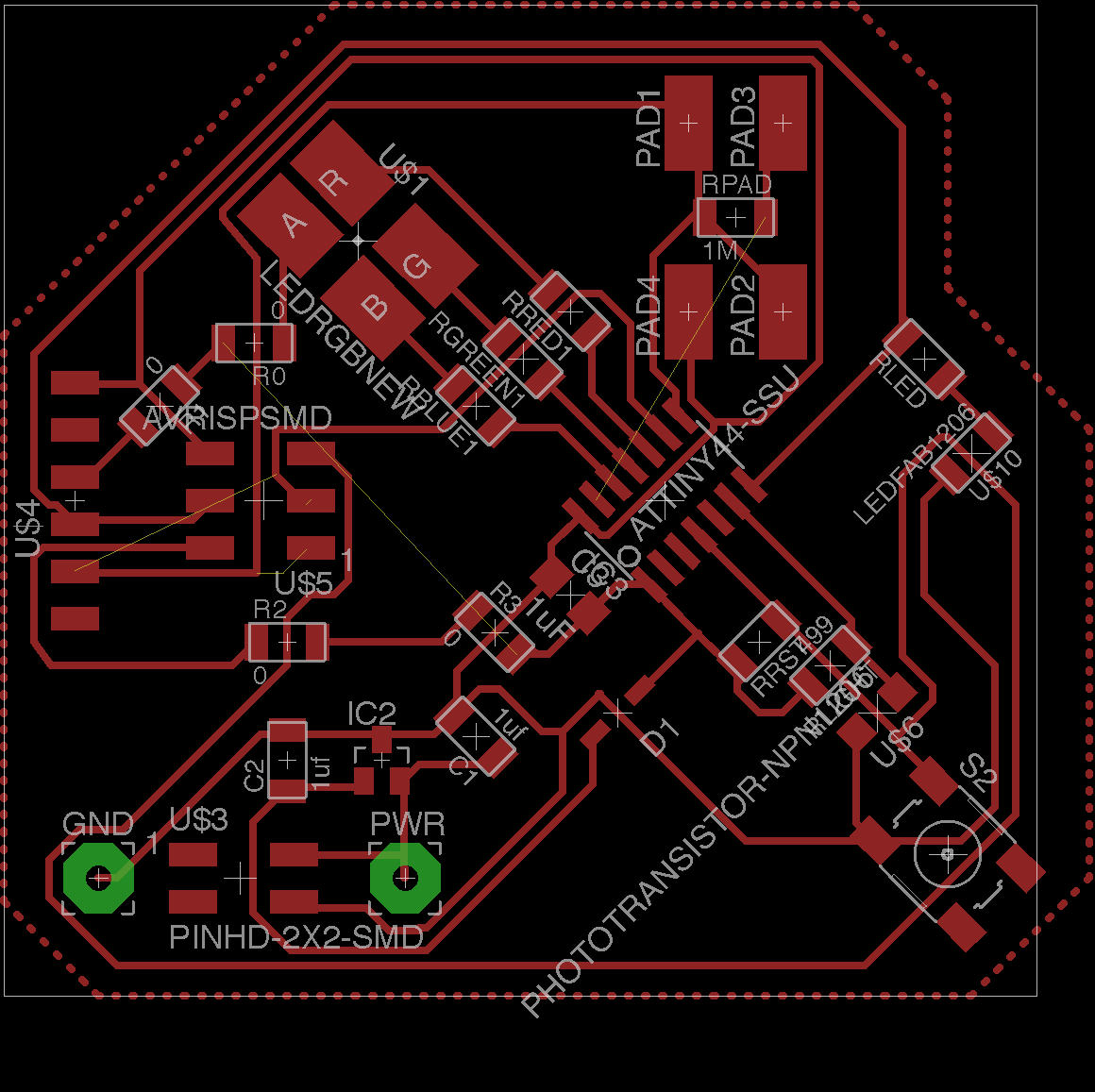
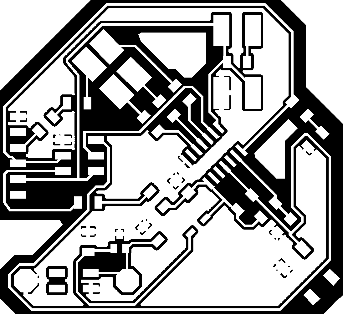
At this point I designed and made board 0.2. The main difference with board 0.1 is:
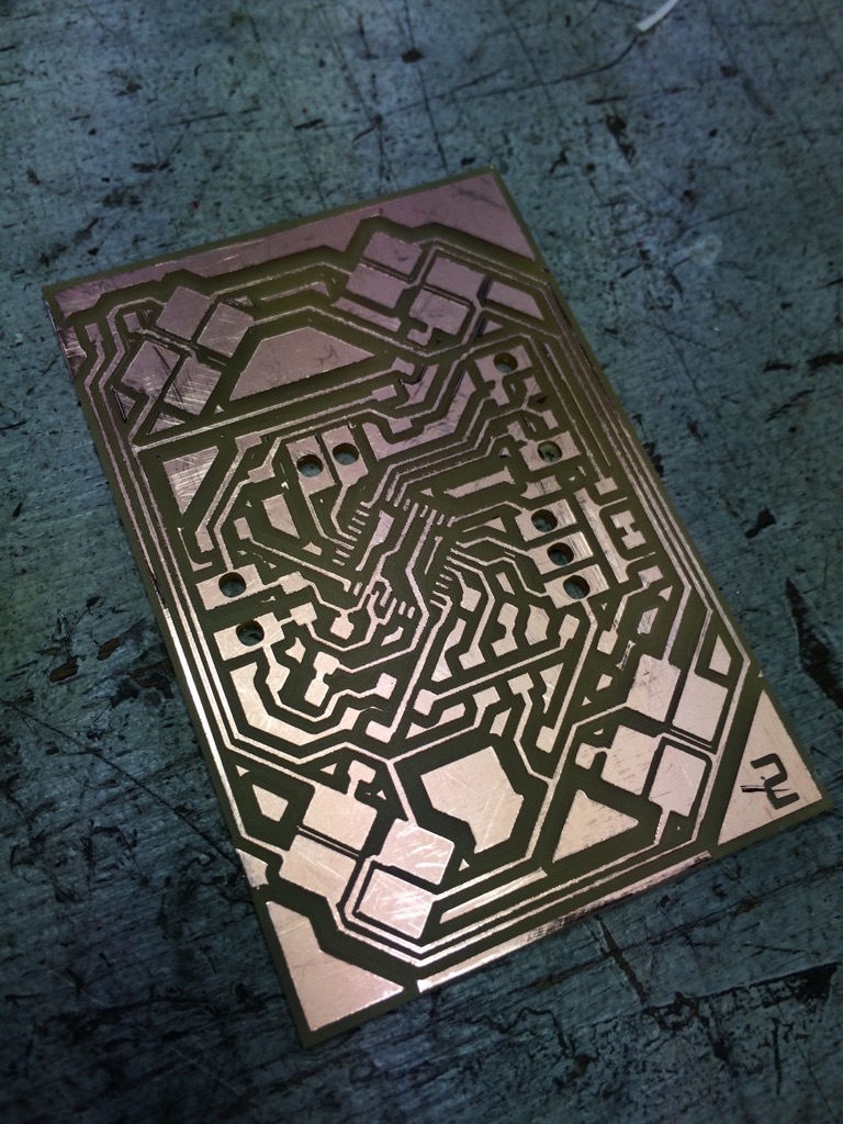
Board 0.2 files:
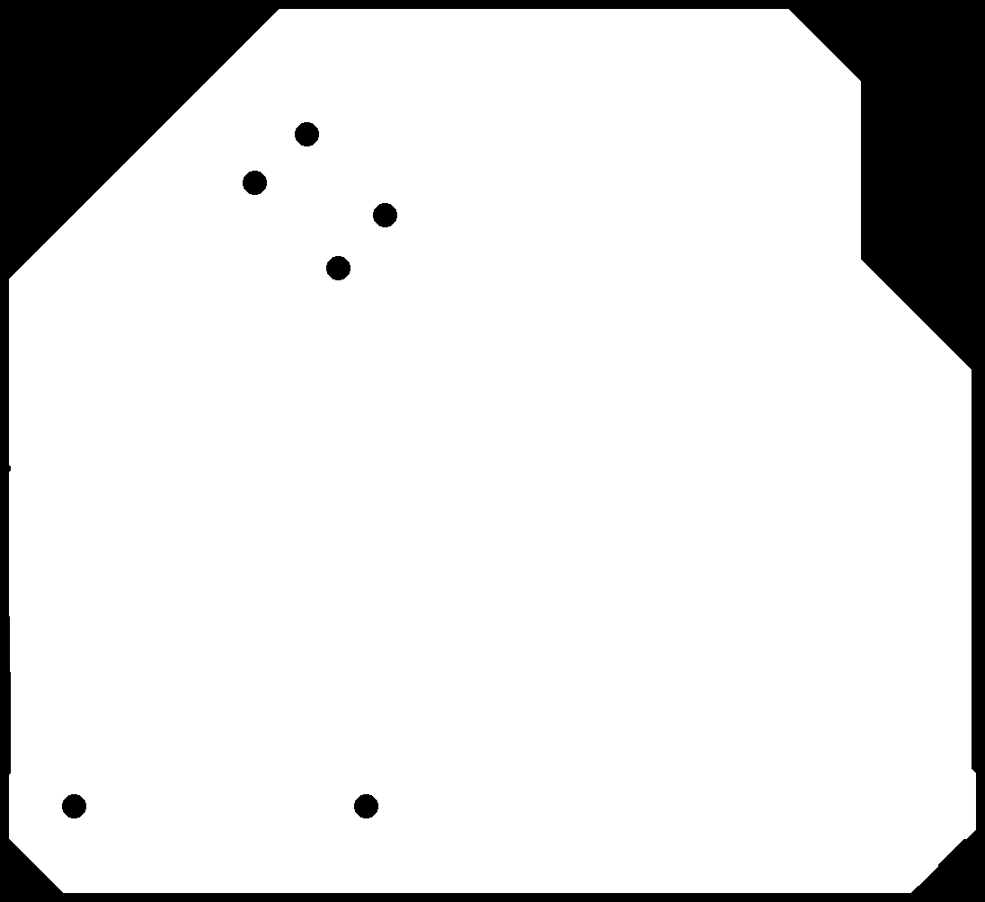
Because of time restraints, I chose to make a board that would be roughly the right size to fit inside the casting. I resized the outer limits of the board area to be roughly those of the casting part. I arranged the LEDs and other components so that they would fit the oval shape of the crystal.
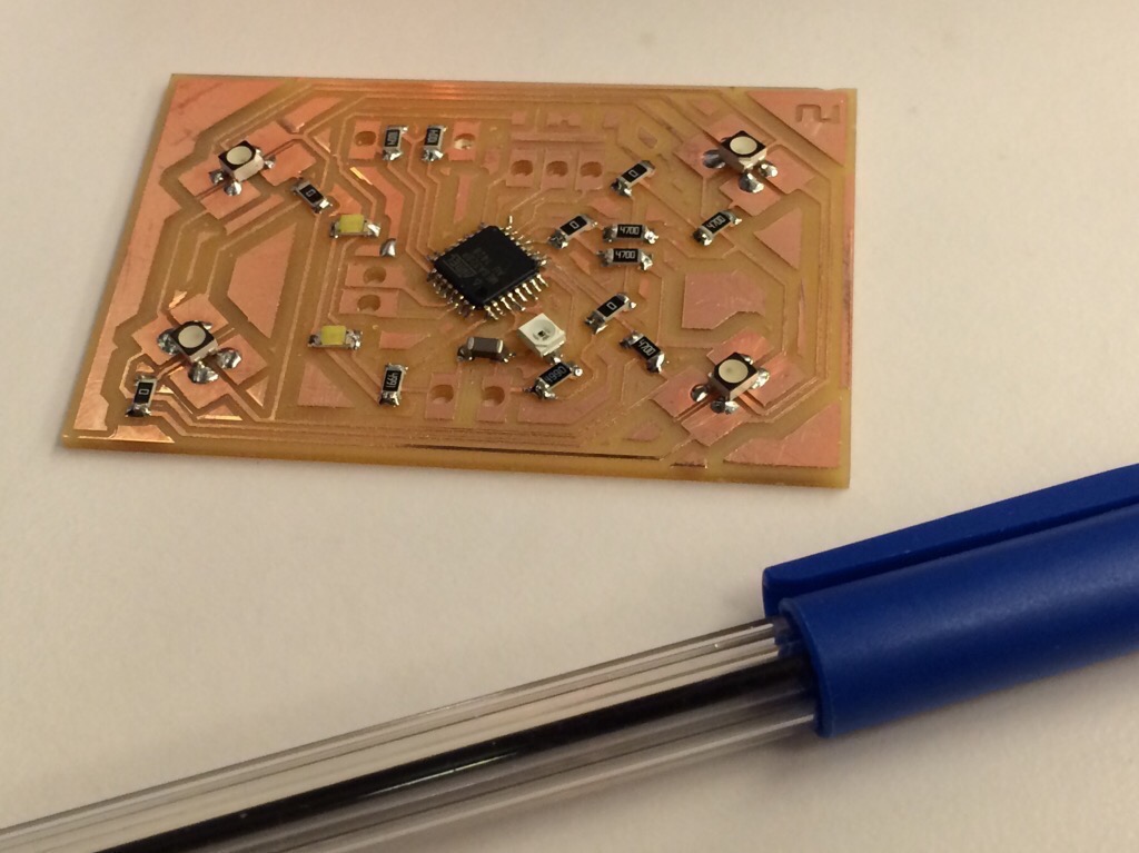
This is an image to show that the board will fit the casing after some finetuning of the layout:
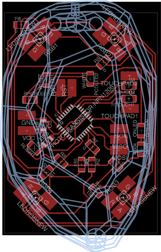
After talking with Zaerc, I realized there might be another way to do this: by importing a shape (or the most significant points) as a bitmap into Eagle and assigning it to an unused layer, I could make a polygon shape of those points and turn that into my outer dimensions for the board. I will use this method for a future iteration of the board.
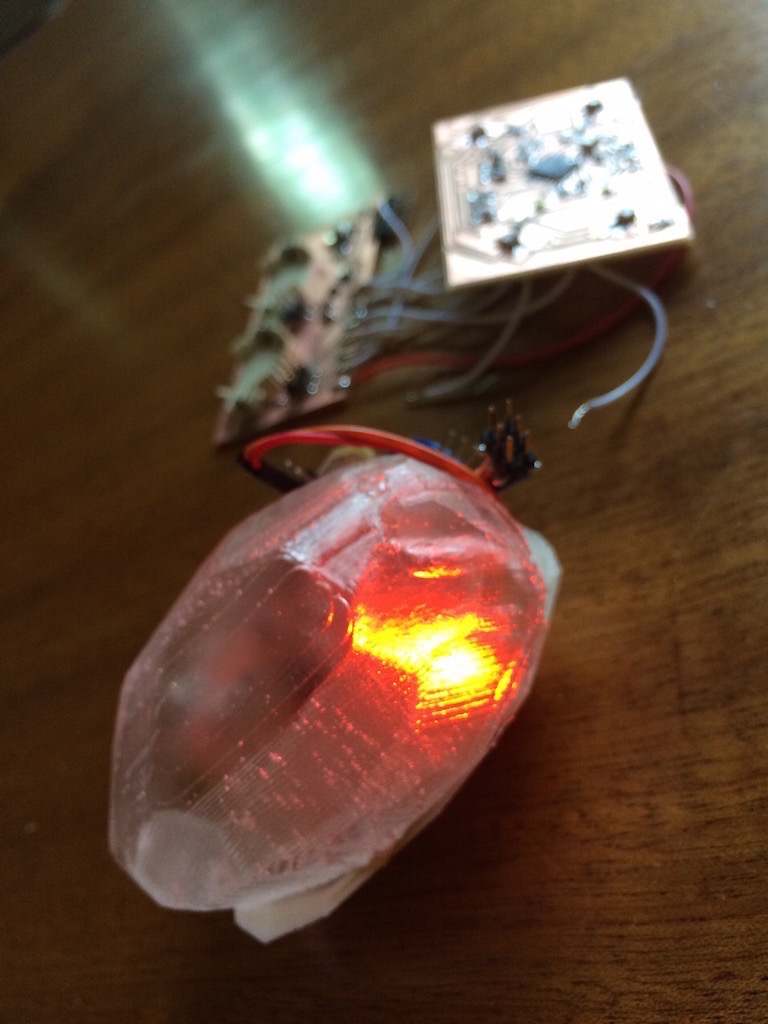
For the presentation I used board 0.1 to demonstrate it. I like how the light is diffused (which is what I wanted - I thought of sanding the casting to get diffused light, but it was not necessary). Wheb you look through the middle, you can clearly see the PCB.
In future iterations, I'd like to work on: