Week 13: Networking and communications
assignment for this week
design and build a wired and/or wireless network connecting at least two processors
This assigment is one of the more difficult ones and even more for me because I experienced already a lot of trouble on the electronic assigments.
So my choice for this moment will be that I want to use Neil's existing designs for serial connection, c-code and make file(s) and hope to get this working.
Links to hello.45.bridge and hello.45.node boards.
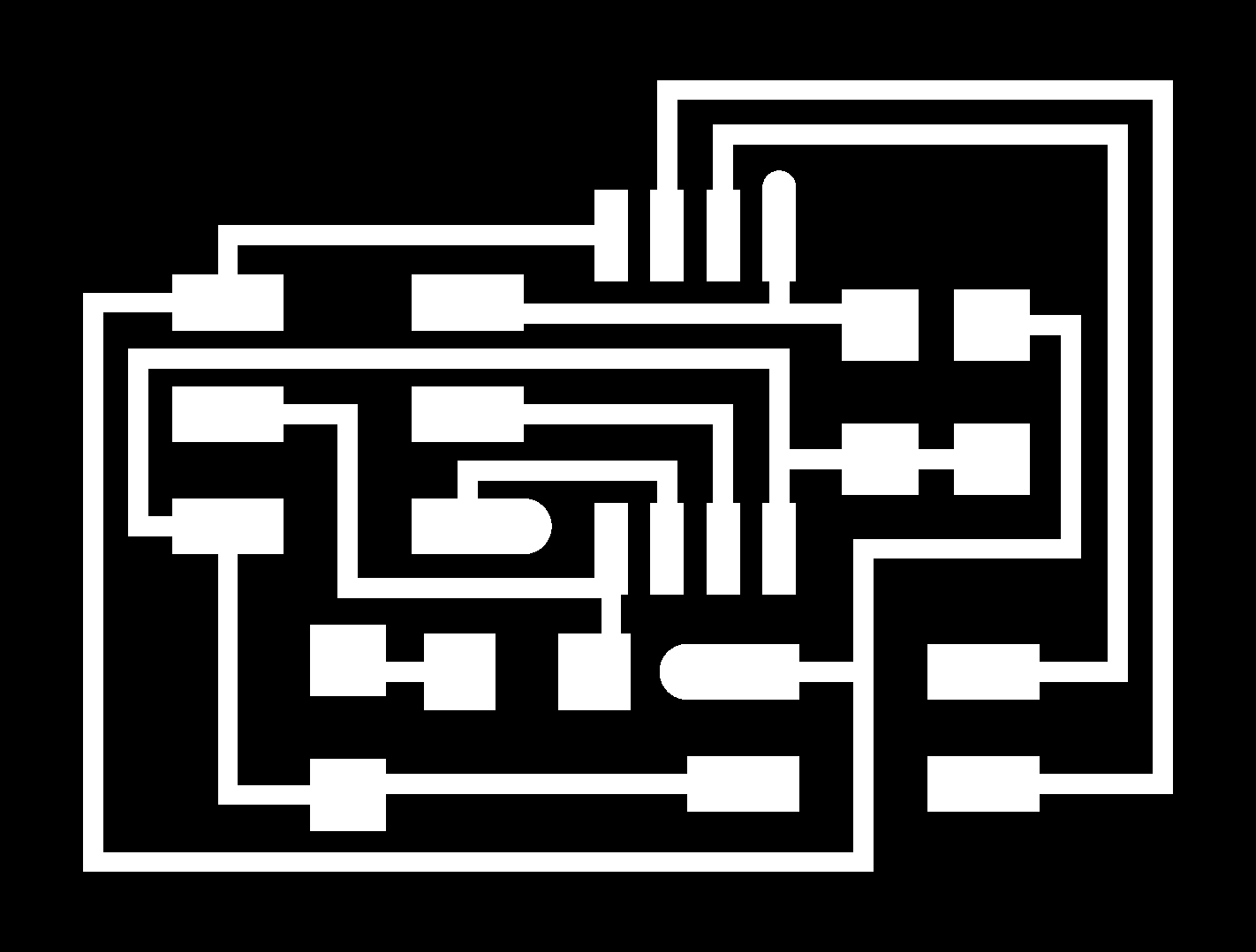
To be able to make one bridge board and two node boards, I made use of the downloadle .png file (traces and interior)
First step is to produce the three boards, starting with the bridge board
For this we will make use ot the Roland Modela and Fab modules software
This is already the third that I made use of this so it already felt familiar.
To recall the right procedure I wrote it down for myself:
Preparation in Fab Modules
Open terminal in Ubuntu
command fab <enter>
This will open up fab modules
select image png
select Roland Modela rml
click make png rml button
click button load.png
select width millbit: milltraces 1/64 inch
Prepation on the Modela
Screw 1/64 inch bit in the spindle (not tight)
Take the Modela out of view mode: button view
Now machine is in run mode to accept commands
On Fab modules:
change values for x en y to a proper position, this will move the spindle
On Modela
Loosen the spindle, allow bit to rest on the pcb
Tighten set screw (now z-axis is set)
On Fab modules
Check all values
make,path (this makes the toolpath)
make .rml (this file will be send to the modela)
Place cover
Begin milling
After milling, click on view button,remove dust
Cut the outline of the pcb
Turn off modela, replace 1/64 inch with 1/32 milling bit
Turn machine back on
Take it out of view mode (view button)
close window, run fab modules again: fab
Same procedure, now load png cutout traces
select 1/32 inch milling bit
On modela:
set same settings for x and y offset
move spindle to the right position
Move z axis around 2 mm above pcb
loosen screw, allow bit to rest on pcb
Tighten screw
move spindle to x en y position
click make path button
click make .rml button
Place cover, begin milling
After milling. remove dust
Cutout outlines of the pcb, both sides
file rough edges, clean surface, use steel rule, rub it across the traces
wash pcb with water and soap
After making some wiring to connect the bridge and two node board this was the result:
Flashing the bridge board
After checking that all connections on the three boards were ok, I connected my bridgeboard to my fabisp
via the programming header.
The FDTI cable I connected to my laptop and my bridgeboard
Following this tutorial I didn't have to change the node numbering because that was already set right to zero (of course I checked if this was the case)
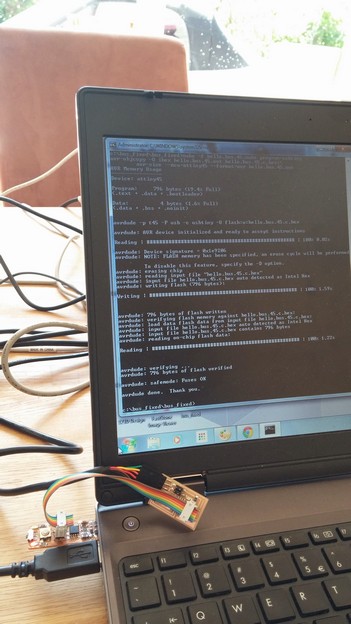
On my Ubuntu laptop I got errors flashing, didn't understand why and than moved to my Windows 7 laptop to see if that would work.
Opening my cmd screen I typed: make -f hello.bus.45.make program-usbtiny
I was very pleasanlty surprised that this worked right away and I was able to flash the bridgeboard.
After flashing the led on the bridge board lit up, I guess that everything is working now.
Flashing node board 1
After a succesful bridge board flash I replaced the bridge board for the first node board
In the c code I changed #define node_id '0' to node_id '1' as said in the instructions manual and saved the file.
After entering the command make -f hello.bus.45.make program-usbtiny this was succesful too and the red led on the node board lit up too.
Flashing node board 2
Now following the same procedure I got an error, so I gues I have to check the soldering on my board again.
Connecting a bridgeboard and one node board to my laptop (via the fdti cable)
Because up till now I got one flashed bridgeboard and one one flashed node board I could already try to make something work.
I connecting bridgeboard, nodeboard to each other and the bridgeboard via the ftdi cable to my laptop
I opened up the Arduino IDE and opened serial monitor from the tools menu
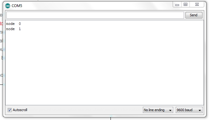
I chose com5 for communication, than I selected from the tools menu: serial monitor.
This opened up a new screen and I type node 0
leds on both boards should flash: they did!
On the sreen I got a response from node 0!
Now I entered node 1, both boards leds flashed again as expected
And the node boards returned an answer with: node 1
So, now everything seems to be working fine in serial communications, much to my relief..:-)
I will repair my second node board and I expect this to be working fine too.
.