This is how not to build a Surf Kayak
Version 0.1
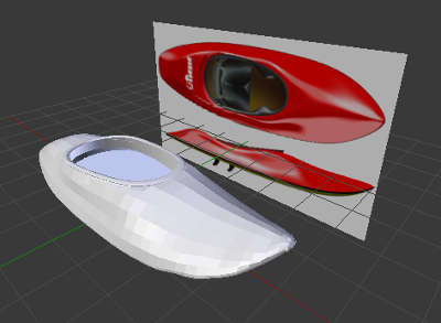
I stared out with classic box modeling in Blender from two images of a surf kayak. However after I got the basic shape I thought it would be more rewarding to design my own, from ground up ...with the risk of it not floating.
Version 0.2
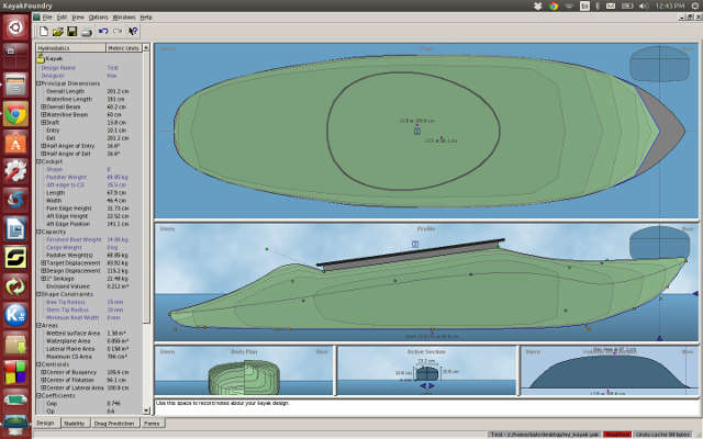
I found a free kayak designing software, KayakFoundry ,yes who would have guessed that existed!
I could quiet easily design a kayak to desired length and the graphs assured me it would float... it even gave me performance curve on water resistant.
The problem however was that it would only allow me to print the design directly on paper (not as a file) or export it as a text file. I had no software that could make any sense of the text file so I ended up exporting (and screen capturing) the shape I needed.
...and then the madness started!
To cut a long 4 day story short:
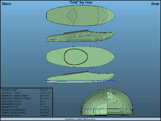
To get a clean image trace in Inkscape I modified the screen shots i took form Kayak foundry in Gimp.
From Inkscape I exported curves i got through trace bitmap to Blender. I had the intersection bits but now needed to ad the rails, I thought it would be simple but as I'm still struggling with Blender, this became a major issue. Some times I got so frustrated that I opened Maya and perform some operations. But I always came back to Blender land as I really wanted to learn it.. For some reason the Boolean command did not work on my objects so I decided to th the intersection cuts as closed objects in Inkscape.
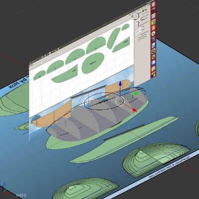
Having finally completed at the modeling majority of the modeling I had to get this back to 2D and Inkscape. I tried many different plug-ins with no success. In the newest version (as of writing) the 2.73a have free style .svg exporter built in to it. It output insane amount of nodes for each curves so I did not use it. In retrospect if I had known then, how well Inkscape simplify curves worked I would have done this.
In the end I went back to Maya (first converting all curves to mesh as Blender and Maya apparently dont talk tha same curve language) vector render it as an Illustator file and form there back to Inkscape.
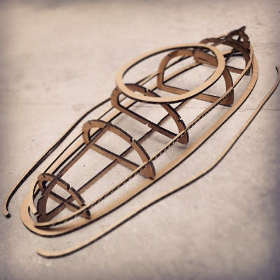
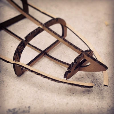
In Inkscape I added the cut outs for the rails and scaled things to proportion and did my first test cut in card board on the laser. Considering the chaos I had been through I was not surprised, although still hoping, to find out that it did not match up... not at all!
I had lost my overview my file structure was a mess, the proportions where no longer matching up and this was as far from parametric design you can get.
Side Project: Cutting Carbon
Two guys in the lab are making a drone and needed a carbon plate for protecting the electronics. I thought this was a good small project to get over my defeat and get some actual machine time.
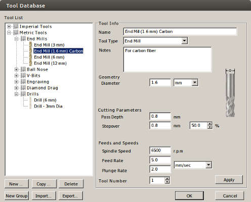
Making tools.
Cutting parameters:
The design file was done but had the following errors.
Problem 1:
The nodes where not align properly in the design file. This weird result when calculating the path.
Solution: In Inkscape snap align all nodes.
Problem 2:
Shapes where not joined in to one single line. This would make the CNC mill each segment all the way through before going to the next segment.
Solution: In cut 2D you can do some edit objects tools one is join open vectors. If you made a tool path for this you need to recalculate.
We exported the file from Cut2D with the Roland - MDX setting this gave us a .rol file. renaming it to .rml and run it through the the fab module with the following terminal command
sudo fab fab_send "filenam".rml
We tried using a small 0.8mm end mill from Dremmel but it turned out that the diameter of the drill was to small so it would not spin around it own axis but do a wobbly motion.
Cutting carbon is very toxic. Its fibers are so short that what you inhale will go to your lungs and stay there for ever. To minimize the health risk we wore masks and used a vacuum cleaner to suck up the dust.
Surf Kayak take two... five!
Re-focus, re-structure and new constraints
I was trying to bend my side rails in two axis, this made it very difficult and probably would not work with the final material. Fransisco suggested that I should do a radial design and let the material constraint, one plywood board, decide how the end design would end up. I did some rough calculations on how many rails I needed and how much I could fit it on one plywood board.
For designing I turned to Rhino, seems like everyone is using it. After half a day of monkeying around with it, without getting any result, I had to face the hard facts. my Rhino/CAD and boat design knowledge is not sufficient enough at this time for me to finish the project. The week had past and I needed to get this project done.
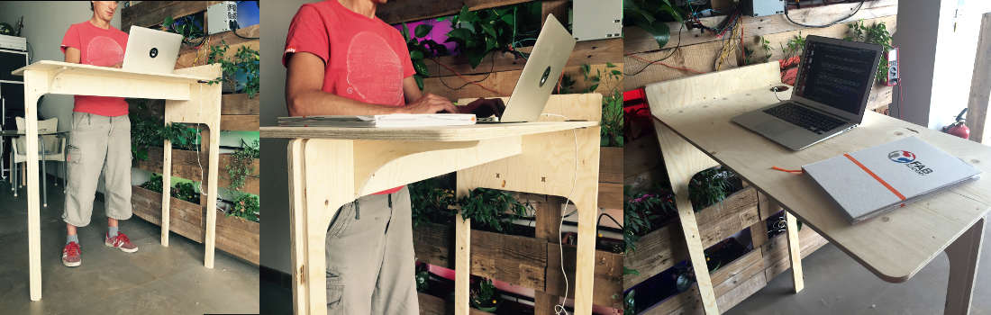
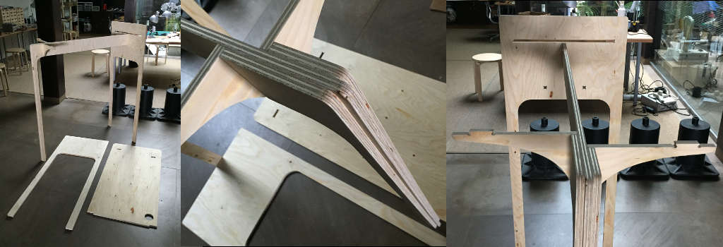
The 3 legged standing work table
I really needed a table for my room. working from the bed sounds great but is in no way practical. I wanted to make it parametric and smart in Antimony, but Antimony kept on crashing on me and crashing hard. So I turned to Inkscape for designing. (later I found out my update script for Antimony was not working properly so I had an outdated version)
I used the clone feature in Inkscape for the tabs and pockets but this later become a problem when I wanted to rotate and re-place my pieces for optimal use of material. Even though they where grouped they would rotate around their own pivot or just "explode" and scatter. I ended up unlinking them all and change them manually. Another "interesting" bug i encounter was that if I used the rotate selection and flip shortcuts Cut 2D would no longer recognize them as line but instead make each line a polygon. Needles to say it took some time for me to figure out the connection.
ShopBoting
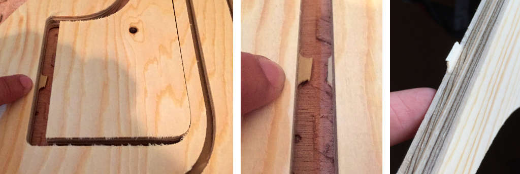
I had made my design on the information that there where a 3mm drill bit for corners and 6mm end mill for cutting. But when we came to Valdaura they had only 6mm end mill, as most of my corners and pockets where going to be hidden so I decided not change the design. I had incorporated a 5cm buffer zone around the edges in my design so fixing the plywood to the sacrificial layer was easy.
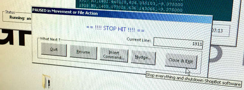
I made a mistake setting up the machine, in order to ensure it would cut the whole way through, as the material was bulging a bit, I increased the material thickness with 2 mm. the result of this was that my tabs got super thin and broke during the milling process.
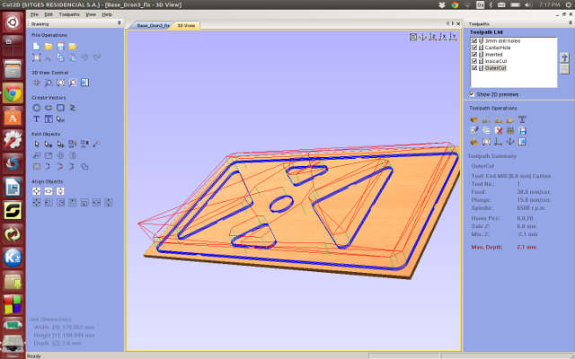
In Cut2D tool settings I had just gone with the defaults but Jonathan at fab lab Valdaura informed us about the optimal speed that he runs the machine at. The job was already running but luckily there where no problems pausing, changing speed setting and continue where we left off
Speed for Shopbot Valdaura
Tool Setting for 6mm End Mill
Cutting Parameters:
Feeds and Speeds
How to adjust speed on the shopBot in the middle of a job.
Assemble
Assembling was pretty straight forward it needed a slight sanding and bit of "sudo" but I was happy to see it fitted together.
 .
.
Unfortunately though the design it self is not very stable. The slim minimalistic style comes at a cost... or maybe just poor design? But put in a corner against a wall it works and I'm very happy to be able to work from home in a comfortable position. Life quality increase: 8%