Designing and milling a Frisbee
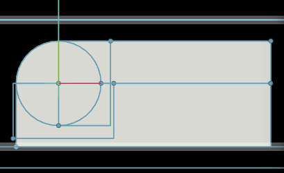
Now with an updated and working antimony I decided to design my frisbee in it. I built a profile curve that I revolved around it self and exported a stl file to Blender for making a two sided mold.
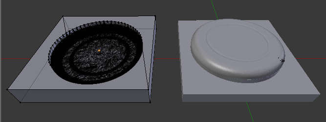
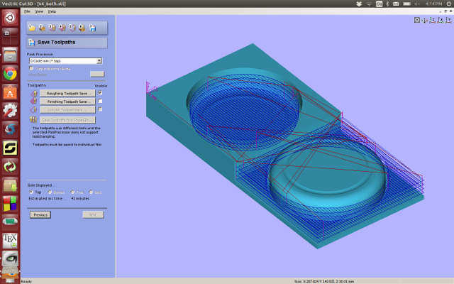
Making the tool path in Cut3D.
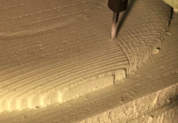
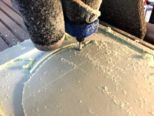
We got a Probotix Fireball V90 CNC machine running with CNC USB controller software. Dimension 50x30x6 cm. After fixing the foam to the bed with double sided tape I checked it the end-mill could reach all corners of the material. It could not, so a quick fix was to loosen some screws for the cutting table to make the small adjustment. Then I set 0 on XYZ and off it went.
The rough pass went fine and I changed the end mill to a 3 mm for final pass and adjusted the Z height for the new end-mill. Running it just in x direction made did not give me a smooth finish so I exported another file for the Y direction. The CNC USB controller software can only export final pass in one direction.(I found out later it can, you just have to find it in the settings)
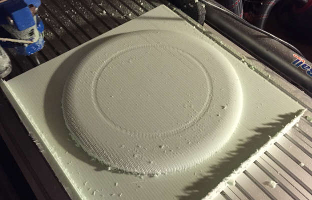 Running the final pass in just one direction.
 Running a second pass in Y direction cleaned up most of it.
This looked pretty good until the CNC decided to dig deep! Stunned at this radical new decision it took me a couple of seconds before I reached for the emergency stop.
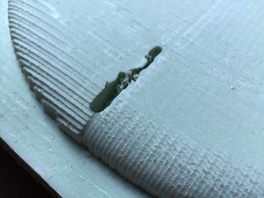 CNC decided to go renegade.
I decided I will fix the rest with sandpaper and cement and charged forward to mill the top mold. But the ghost of the CNC machine was not pleased so at the end of the first pass the end mill just went in to the center of the piece and performed irrational spastic movement, combined with loud ugly sound. (missing steps) It could have been a modern art performing piece if there right crowed where watching, sadly there where no such crowd, only me cursing out loudly. I pressed stop and go to 0, only to find that the the spindle went of in max X & Y and started grinding against the wall for a bit. No need to say but the 0 point was obviously lost. I tried to re-align manually to do a final pass. But the final pass only cut 1 cm down, leaving me with a flat cylinder.
Back to the drawing board
A part from last night freak out the dimension where off. it was compressed and the top mold had no curvature at all. So I started by looking in to why the top mold would not mill to the right depth. I noticed that there where an extra polygon layer, with flipped normals, in the middle of the design, something had gone wrong in the boolean operation in Blender. I went back through my files and tried to clean it up but with the unstructured mesh that comes out of Antimony combine with boolean operators is just a nightmare to clean up. So I unconnected some nodes and started re doing the frisbee in antimony
Still having molding and casting in my head I forgot that for composite I don't need to model the thickness but can make it solid. Changing this also fixed the weird Boolean result I got earlier.
 Running the final pass in just one direction.
 Running a second pass in Y direction cleaned up most of it.
In the end I did both mold half's in Antimony. Combined them in Blender to one single file (could also have done also this in Antimony) and then Cut3D for the tool path.
I decided to set the feed rate down, hoping that was the cause of last nights machine fail. It all looked great to start with, but again after the first layer the machine did a loud twitched and went of in a arbitrary direction.
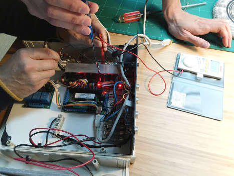
Calibrating the CNC.
Talking with Francisco about all the problems we had over the past days he said that it sounds like a pulse problem. If the pulses are of that would make the motors stall, skip steps and as a result of that have erratic movements
We got the newest software update and download and imported the settings file for the stepper motors. This change a a lot of parameters stepper distance, speed and now the sound of the motors where completely different. What it also did was to inverted the coordinate system and change to the imperial measure system. Plunging 2 units now suddenly become 50.8mm!!! Good thing with an external emergency stop button.
Now for some tests, we did it the hard core way and wrote our own G-code command to drive the steppers 10 cm and then measure it. Turned out that it only went 5 cm, half distance. So we doubled the step size and this time we went even more precise by putting a caliper against the end mill measuring it as it moved down X axis. There where still a 0.18 offset but we decided to stick with the doubling as are not to happy about uneven steps.
Thinking all was fine and dandy my class mate run her job, but again, after the first layer same thing, it missed some steps and went all renegade. So now we tried moving driving the motors while the end mill was submerge in the form, it did not skip any step... what ever we did it would not get it to skip a step. So we offset the spindle in the Y axis and run a "dry" run. It always went wrong when it got to this point where it got to cutting the profile. So removing this option and another "dry" run and all worked fine... or so we thought.
CNC Missing Steps from Anders Haldin on Vimeo.
With the CNC still not behaving we tried to change the acceleration settings thinking that might be the cause of missing step. We also tried wit different feed rates and speed. We dug in to the data sheet for the motors and change the steps from 1/4 steps to 1/2 steps and adjusted voltage for it. On the support web site we found a export plug-in for cut 3D replacing the G-code.tap
Things got better but we could never get it to run a complete job without it skipping steps.
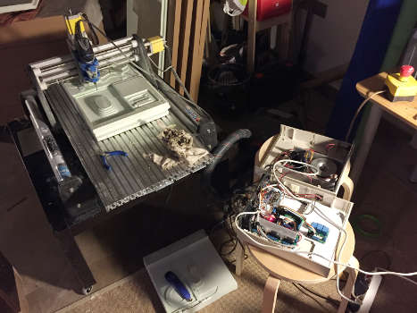 The gutted machine.
 Adjusting voltage after the steppers have been changed.
With all theses problems taking a lot of time, I decided to just do my frisbee with out the top mold and go for a bleeder/breather layers and a vacuum bag.
Cutting the linen.
But first I needed to cut the fabric in the right shape to make it fold nicely over the edge. I could no longer refer to my design file as the uncalibrated CNC had squished and stretched the design.
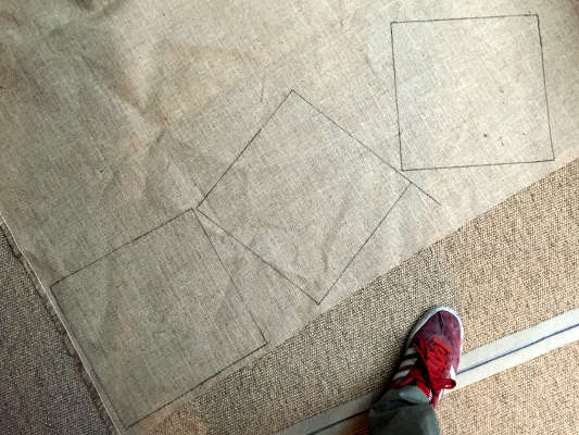
Measuring it to the best of my ability with a ruler and caliper and then using Draftsight to draw out the measurement, trying to make the right calculation for cutting the fabric so it folds nicely over the edge.
 Using Draftsight to get the right angle for my side flaps.
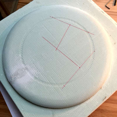 Finding the center.
I did a test cut and tried it on the mold. For some reason it was way to big. Roughly 1.5cm on each side... numbers seemed to roughly add up, and roughly being the important word here. So turning my back on fancy math and cad software I tooke a string measured it across the center and got the diameter for my 2D file.
 Rotating the template to get crossing fibers
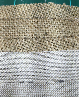
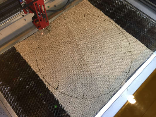 Sweet smell of laser cutting burlap.
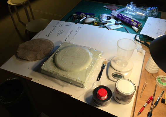
Smelly Cream Cake
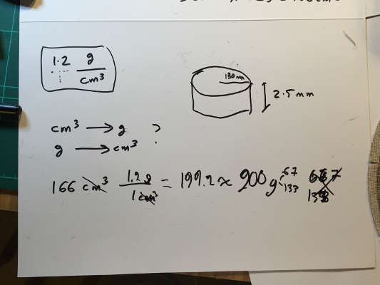
We used SO124 UV resin Epoxy. I wanted roughly the same volume as my fabric plus a bit extra that will stick to my cup. So for calculating the amount of resin I need, I measured my fabric, it had a radius of 130 mm and a depth of 2.5 mm. Using Google to figure out the volume of that cylinder.
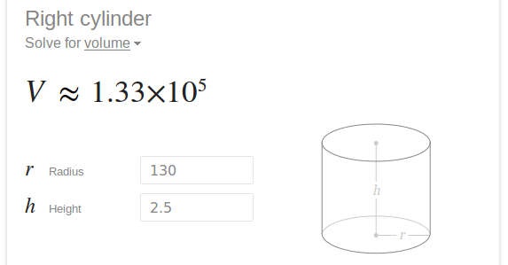
 .
.
Density (g/cm3) for Epoxy is 1.1-1.4 I go with 1.2. The mixing ration is 2 to 1. Giving the end result of 199.2 or 200g.
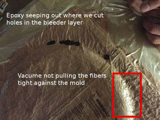
Started with a layer of plastic food wrap on my mold then applying the epoxy to both sides of my fibers and layer them like a cream cake, making sure that the fibers cross in different direction and my side cut get offset from each other. Another plastic food wrap as bleeder layer and a towel for breather. We cut some holes around the mold in the plastic wrap for the epoxy to go out when in vacuum.
 .
.
In the vacuum bag I noticed that there where a "skirt" fanning out. As the vacuum bag lost pressure I pressed the edge in towards the mold and did a new vacuum. I repeated this a couple of times.
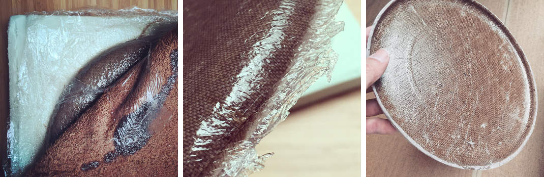
The Result.
Removing it from the mold was easy but removing the plastic food film was impossible, it had merged with the epoxy and gave it a glossy plastic look. I really wanted the natural fibers back so I started sanding.
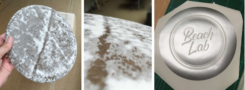
I took the Beach Lab logo and did a vinyl cut for a stencil and started spray painting. I noticed that after about 4 layers of paint the stencil would start to peal off in the edges, probably because of the paint shrinks a tiny bit when drying. Next time I do something similar I would probably cover that mask with a piece of cardboard for it to get less paint on it. Lastly I did clear coat for it to be water resistant..
It is flying!
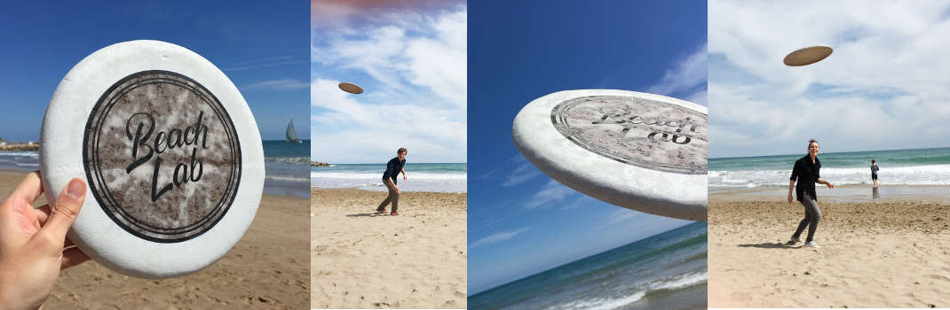 It it s built on the heavy side for a frisbee but it is flying great.