week_07 embedded programming
Tasks
- read a microcontroller data sheet
- program the board to do something
programming the board

software: Arduino 1.6.1
library: attiny-ide-1.6.x
location: Green FabLab Valldaura (BCN)
how to:
- at first you need to know the corresponding pins between the attiny44 and the arduino
- download library from github > create a folder "hardware" in the sketchbook folder of arduino (check preferences for location) > paste the attiny folder into the hardware folder

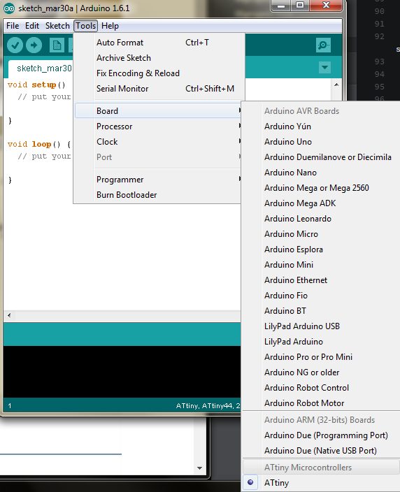
- start arduino ide > tools > board > attiny
- tools > programmer > USBtinyISP
- tools > clock > 20 mhz
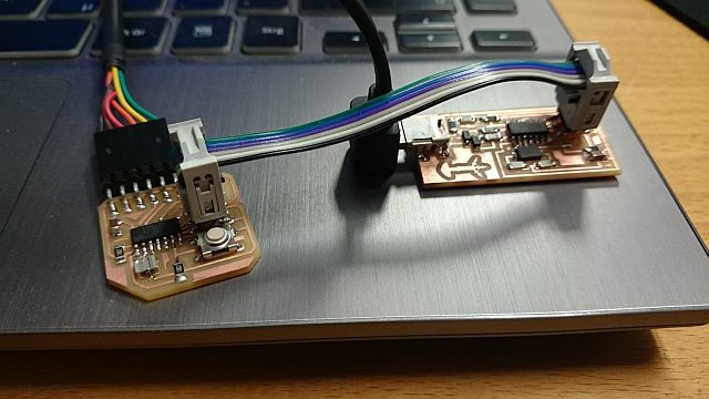
- connect the fabisp with the board via a isp cable, make shure the
ground goes to ground!!!
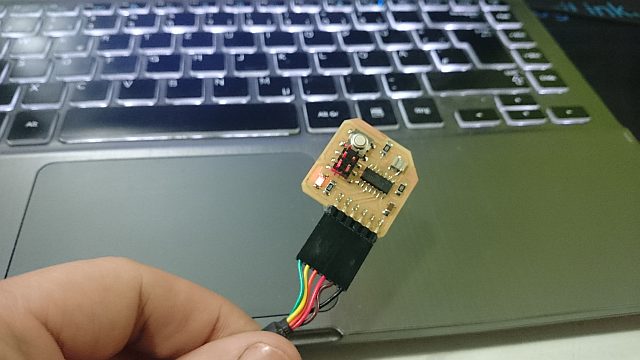
- connect a ftdi cable to the board, make shure the ground is in the right place!!!
- once the board is programmed, the fab isp is not needed anymore, a communication to the board directly should be possible.
- i made the LED blink with the examples in arduino
/*
  Blink
  Turns on an LED on for one second, then off for one second, repeatedly.

  Most Arduinos have an on-board LED you can control. On the Uno and
  Leonardo, it is attached to digital pin 13. If you're unsure what
  pin the on-board LED is connected to on your Arduino model, check
  the documentation at http://arduino.cc

  This example code is in the public domain.

  modified 8 May 2014
  by Scott Fitzgerald
 */


// the setup function runs once when you press reset or power the board
void setup() {
  // initialize digital pin 13 as an output.
  pinMode(13, OUTPUT);
}

// the loop function runs over and over again forever
void loop() {
  digitalWrite(13, HIGH);   // turn the LED on (HIGH is the voltage level)
  delay(1000);              // wait for a second
  digitalWrite(13, LOW);    // turn the LED off by making the voltage LOW
  delay(1000);              // wait for a second
}