This week's assignment is similar to the input devices one, but instead of designing a board to receive data from the outside, a board with output devices must be built. Some examples are: screens, buzzers, RGB leds, engines, etc. must be designed.
The first prototype of the incubator will include two boards that match with this assignment:
Control panel
The control panel will consist of:
- Joystick + button: this input device will allows the doctor/nurse to interact with the incubator. For example, changing the temperature.
- RGB led: output device to tell if everything is OK (green), may be checked (yellow) or if attention is needed (red).
- LCD screen: will display the incubator status.
- Buzzer: output device to improve the user experience. For example, if a button is clicked, the incubator will "buzz", indicating that the action has been read.
Continuing with last week's strategy, I designed a new shield for my modified version of the FabKit board.
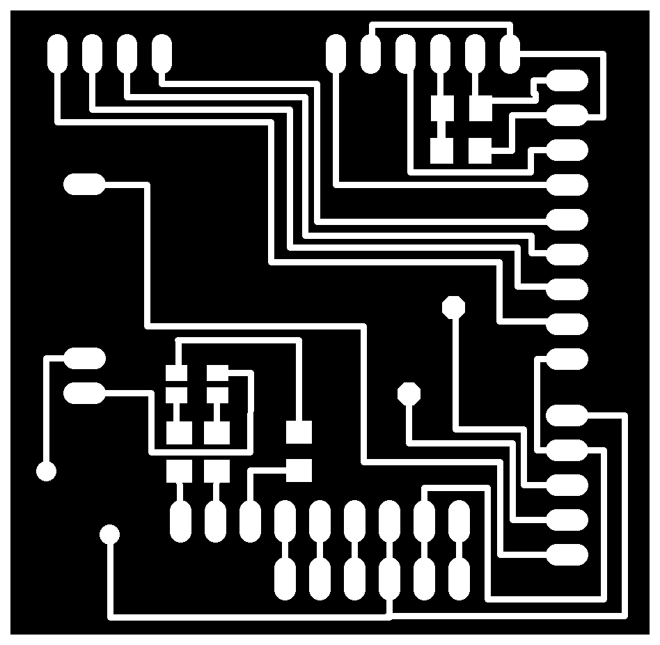
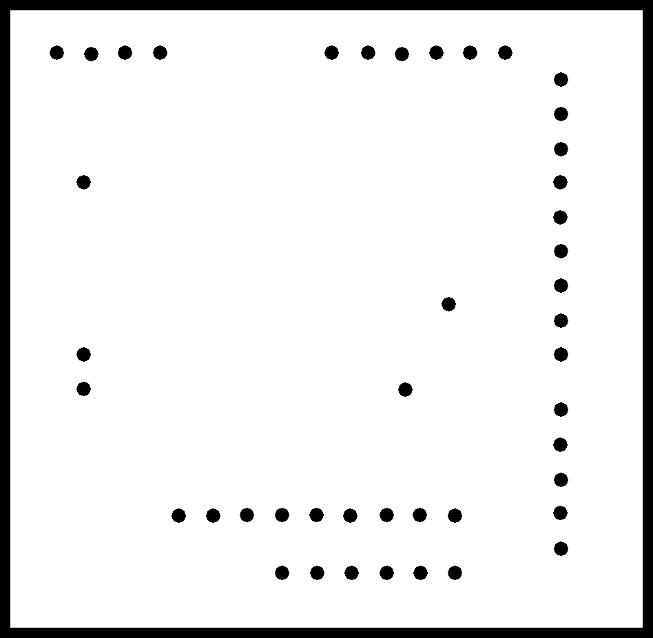
Once cut and welded is ready to be programed.
The code below is a demo which displays [using the LCD display] the position of the joystick (0-1023) for the x and y axes, buzzes when the button is pressed and changes the RGB led color depending on the position of the joystick.
Building FabKit shields is great for testing and learning how to program each device, but I am not sure if it is the best approach for the incubator. For example: this board requires almost every pin of the ATmega168A. Therefore, I wont be able to manage a NTC thermistor, a humidity sensor, water sensor and an engine. Probably, the final prototype will consist of several independent circuits (each one with its own microcontroller) communicating through serial port, I2C or any other protocol.
Power supply
The incubator will be able to tilt the bed using one or two stepper motors and its corresponding gears. I'd also like a first prototype pluggable to a 12V car battery. This means that the final circuit of the incubator will need middleware circuit to prepare the input voltage to feed the electronics (5V) and the stepper motors (12V).
I decided to design an independent board that, given a 12V power source, it can feed 12V and 5V systems.
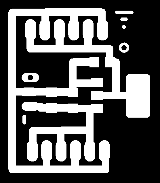

As seen, it has 2 pin input for GND and VCC, 3 pair of 5V+GND, and 3 pair of 12V+GND pins.
In3
The incubator has several output devices.
The ones we are most used to deal with are the LCD display and the RGB led. Both of them have already been described. This devices are placed in the control panel board.
The temperature board is a little bit more tricky. It has 2 different types of output devices(in fact it has 3, but only 2 of them working right now):
- Relays to turn on and of the Peltier module.
- Fans to dissipate the cool or heat produced by the Peltier module.
The third output module is a pump to increase the humidity inside the incubator.
The boards and code of this input devices can be found in the final project page.