The design
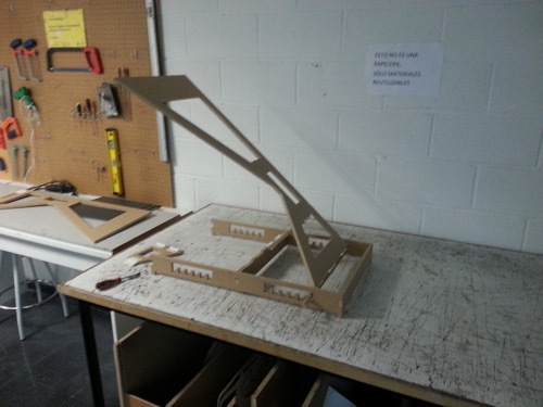
A few weeks ago, using the laser cutter, I built a scaled version of the tilting legs. That design let me find its weakest points that needed to be redesigned.
Those errors took me to a second and more robust design.
Preparing the design
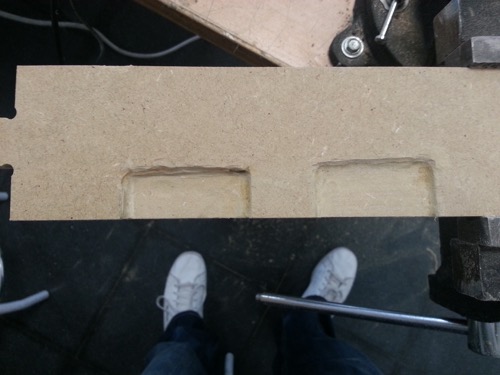
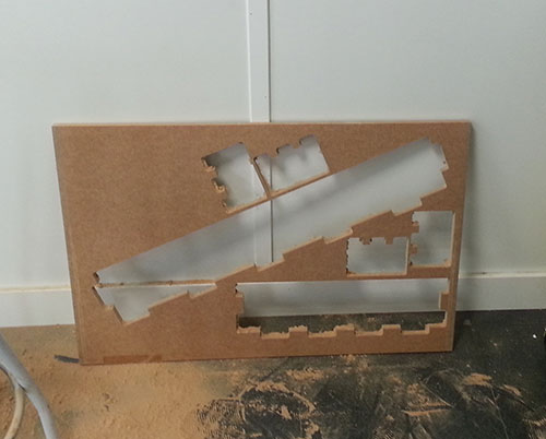
Before exporting the design I shaped a template to define the clearance between the different pieces to do a press-fit construction.
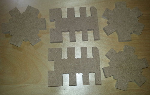
As seen, I cut more than once the template. I made a mistake designing the notches of the rectangular piece. The first notch had the exact same with than the board but, the other ones, instead adding extra space to fit the pieces I was decreasing the notch size. The same issue was detected on the hexagon. Once I redesigned the piece, everything was O.K.
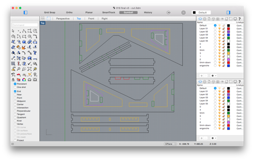
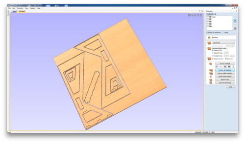
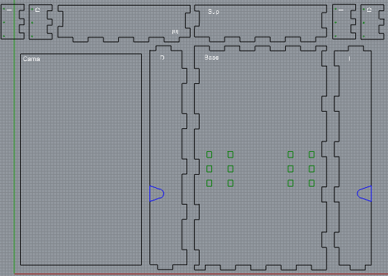
The next step was exporting the polylines in a "*.dxf" file and, using VCarve, import that file to prepare the design to be cut using the CNC machine.
Once in VCarve I could fillet the corners, rearrange the elements to maximize space utilization and define the milling path.
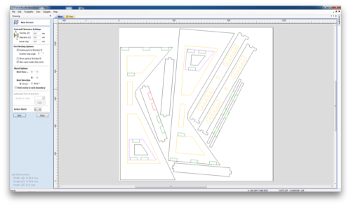
Nesting vectors
Despite I tried to maximize the space usage using Rhino, I decided to give a chance to the rearranging tool of VCarve. I started changing the parameter until I got the expected result:
- Clearance: 6mm
- Tool Diameter: 6mm
- Rotation step angle: 5 deg.
- Allow parts inside other parts: yes
Filleting corners
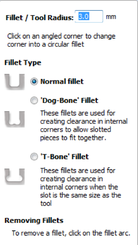
Designs with right angles are not recommended to be cut by a CNC machine. A right angle will cause the machine to stop completely and start a new movement.
Instead, if the right angles are defined as very small curves (0.1mm radius), the machine will decrease its speed to change de direction before increasing it again. The result will be smoother and the machine won't suffer that much.The mill shape is cylindrical, which means that the machine will not be able to create perfect right angles, instead we will get a small curve on every corner. This might be a problem sometimes, but if we want to do a press-fit or match two pieces, the joints won't match. In order to fix that we can use a 'Dog-bone' or 'T-bone' fillet. This fillets will add an extra space that allows two pieces to fit perfectly. I have used the same radius than the mill.
Defining the paths
I defined a different path for each layer. The cut must be performed from the inner paths to the outer ones, preceded by the recesses for the notches.
I am going to use an end mill cutter with two lips and a diameter of 6mm for every path.
The notches path was defined using the 'Pocket Toolpath' tool using this configuration:
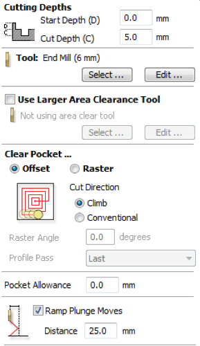
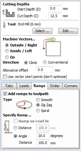
Finally, using the '2D Profile Toolpath' I defined the properties of the path. I added some tabs to the vectors and defined the 'Ramp'. I also chose the depth of each milling pass to make it a little bit lower than the mill diameter. Finally, depending on the piece to be cut, the path should be done form the inside or the outside of the vector.
Milling
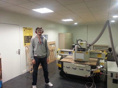
Once I learnt the basics about the CNC machine (parts, commands, parameters, security tips), I attached the 6mm two lips flat end mill and started milling the legs of the incubator. The speed of the mill is 3,000mm/s.
A few minutes later I realized that the design was wrong. Instead of rotating 180º the second pair of pieces that shape the legs, I mirrored them. The result was having two pieces with the notches in the wrong side.
Also, as the crosspiece had notches on both sides of it, I had to use a Dremel to make those recesses. The result was far from perfect.
I solved those problems and improved the design of other pieces. Finally I milled the redesigned pieces.
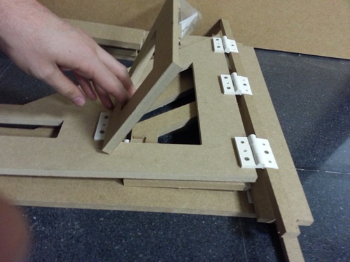
Assembling
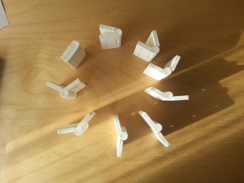
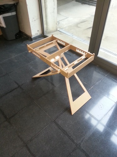
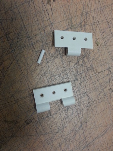
Using the hinges designed a few weeks ago, I assembled all the milled parts.
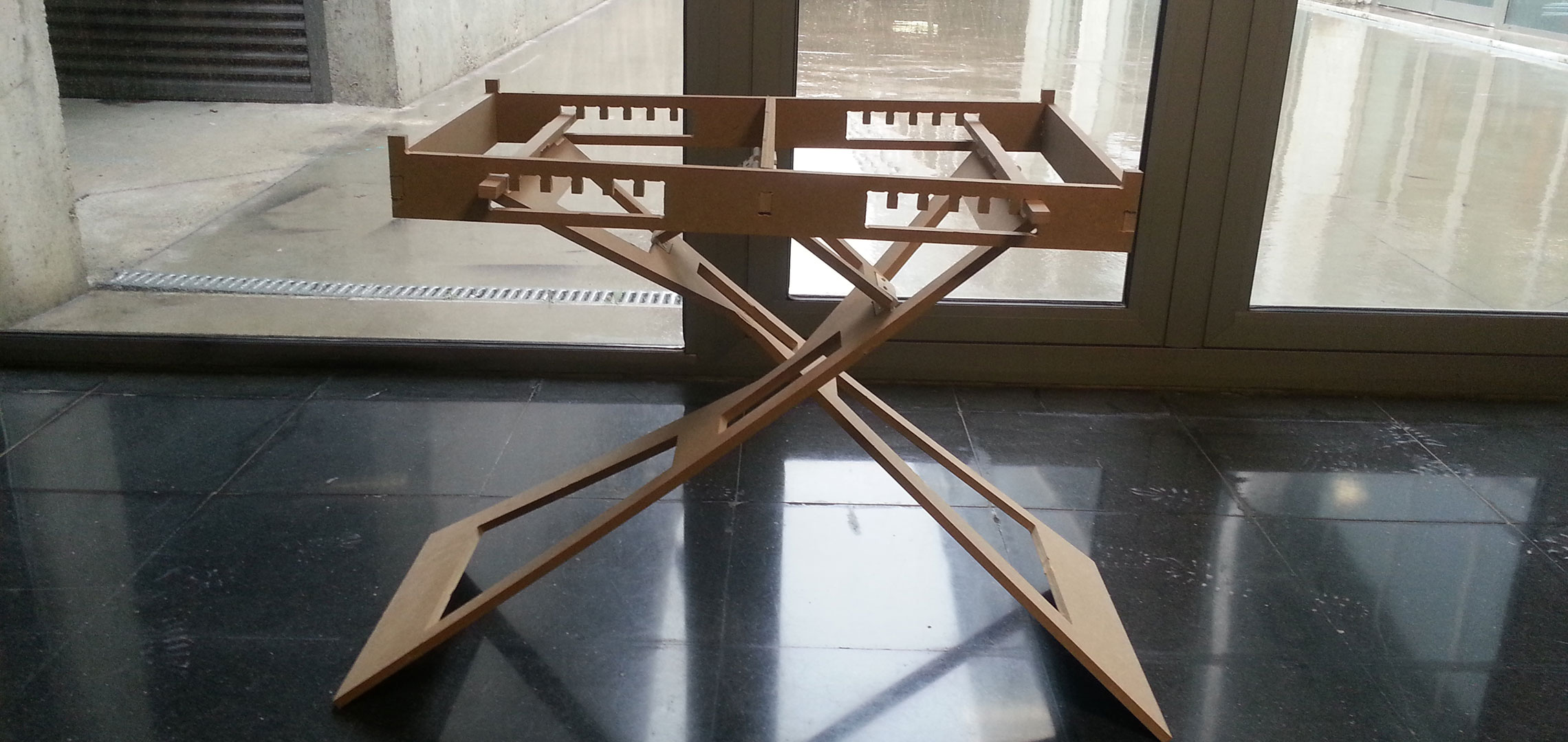
While I was changing the height and the inclination of the structure, one of the hinges broke. Once replaced, the same hinge on the oposite leg broke. This issue is making me rethink the design to reduce the moving parts while maintaining the tilting feature and reducing the effort of that hinge. Anyhow, I realized that a diameter of 2mm for a plastic rod, is not the best option. For the next design I am planning to replace the printed hinge with metal hinges.
Besides that problem, I realized that the structure load should be better distributed in order to increase the stability. Currently the legs angle tends to increase dramatically when extra weight is being supported.
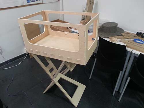
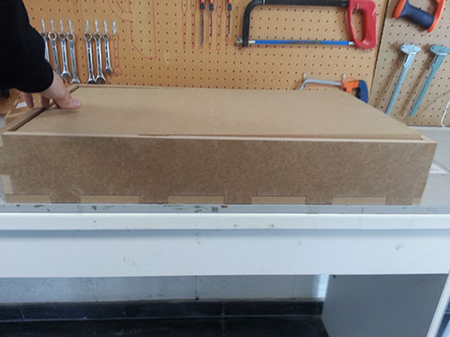
Box
Additionally I decided to build the first prototype of the incubator box. This structure will have the box to fit the electronics and the tilting bed. Taking into consideration that this week assignment was creating something using molding and casting techniques, I designed the box mixing both approaches.
This time, instead of using MDF of 12mm, I am using 16mm and almost every joint of the box are using press-fit.
But the tilting axis will be done by fitting a plastic piece inside a rounded notch on each side of the box.
This is the end result.
The final prototype will not be made of MDF, but it is cheap enough to iterate through the different designs, allowing me to build and test as many designs as possible.
Final design
Those designs lead me to a new [3rd]iteration of the box and legs design. Separating both parts could look like a good idea at first, but the stability of the device was not as good as it should be.
The new design provides the incubator with a better (not perfect yet) load distribution, reducing significantly its momentum.
The legs are cut using 1.75 cm plywood. The box walls using 1 cm plywood and the box base with 3.5 cm plywood.
I did the 3.5 cm thick board sticking two 1.75 cm thick boards and milling it two days after.