Fab Academy 2015
Fab Academy
How to Make Almost Anything...
How to Make Almost Anything...
This weekly assignment consist in read a microcontroller data sheet (attiny44) to understand the functioning of our microcontroller and program my board (hello world) to do something, with as many different programming languages and programming environments as possible.
This assignment it's the continuation of Electronics Design Assignment and also need FabISP so to perform the task, it will be necessary:
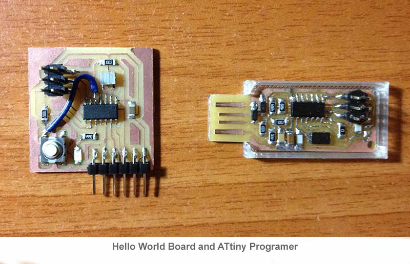
You need an in-system programmer (ISP), I use the FabIsp made in class. You also need the board to be programmed, in my case I'm going to program "Hello World Board".
I'm going to program the board using Arduino IDE Software, so the first thing I have to download is the Arduino programming environment, installation instructions are available for Windows and for Mac OS X.
Arduino doesn't work with the Attiny by default, so it's necessary download the ATtiny Board Files you can do it here.
Make sure you have the FTDI Drivers installed, if you don't have installed, you can download here.
To work with the ATtiny, you must install the corresponding libraries, for this:
With these changes, the next time you restart, you should see in the Arduino IDE Software ATtiny's boards
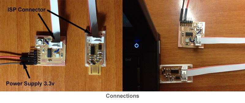
You'll need to provide power to the ATtiny and connect it to your programmer (FabISP). to provide power to the board, I'm going to use the FTDI connector pin (Vcc and GND), should be supplied 3.3 volts to these pins. For ISP connector must be matched MISO, MOSI, SCK, RESET, VCC, and GND on both sides of the cable.
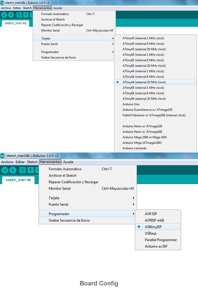
First thing to do when programming with Arduino IDE is select the board to program (ATtiny44 with external 20 Mhz clock), the programmer that we will use (USBTinyISP) and the USB port where we connect the programmer.
Before scheduling the board I read the most important parameters of the datasheet to understand the functioning, know a little better the chip and know things like the equivalence between pins, something very important when programming with Arduino IDE since the equivalence between pins is totally different. Through the datasheet I could also find MISO, MOSI, SCK, RESET... in addition to the pins function as PWM or analogies inputs
The pinouts on the ATtiny are not the same numbers in the Arduino code, this is the corresponding between Arduino and ATtiny pins.
| ATtiny 44A Pin Number | Corresponding Arduino Pin Number | Details |
| 1 | - | Vcc (+) |
| 2 | Pin 10 | 94 |
| 3 | Pin 9 | 94 |
| 4 | - | RESET |
| 5 | Pin 8 | PWM |
| 6 | Pin 7 | PWM, Analog Input 7 |
| 7 | Pin 6 | MOSI, PWM, Analog Input 6 |
| 8 | Pin 5 | Analog Input 5, PWM, MISO |
| 9 | Pin 4 | Analog Input 4, SCK |
| 10 | Pin 3 | Analog Input 3 |
| 11 | Pin 2 | Analog Input 2 |
| 12 | Pin 1 | Analog Input 1 |
| 13 | Pin 0 | Analog Input 0, AREF |
| 14 | - | GND (-) |
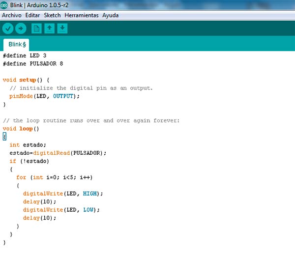
The program I'm going to do is very simple, when you press the button, the LED will blink 5 times. This is the code: