Fab Academy 2015
Fab Academy
How to Make Almost Anything...
How to Make Almost Anything...
This week we have to build our own ISP programmer, for that I have to learn to use the milling circuit machine, soldering the components to the PCB and load the firmware to the chip.
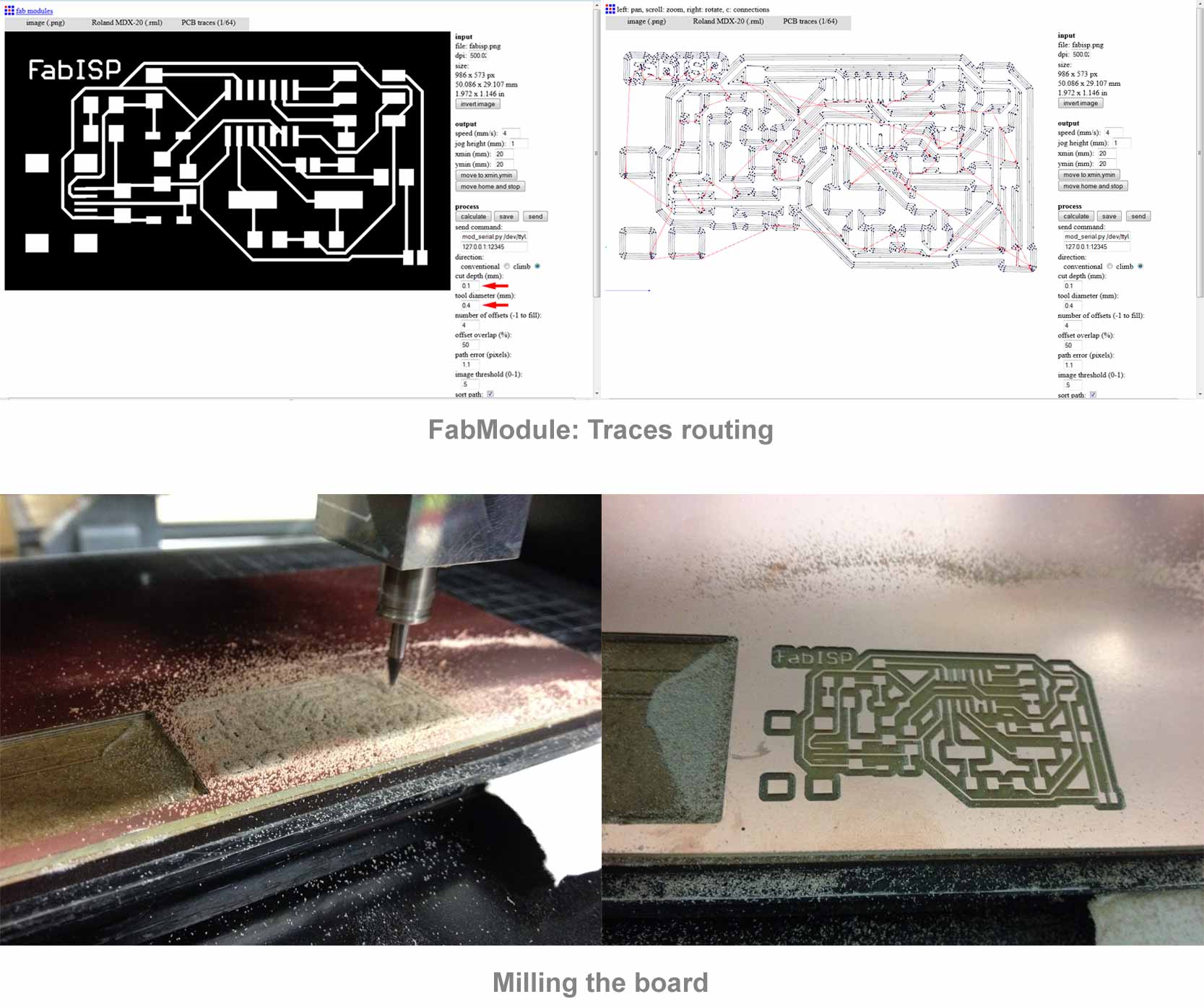
For milling the circuit I used a Roland MDX-20. Milling work is divided into two phases, milling the PCB traces and the out line, each of these phases has a milling cutter and different settings. Between the 3 options, I chose to make the ISP programmer of David I think it's a good design and I like the USB connection.
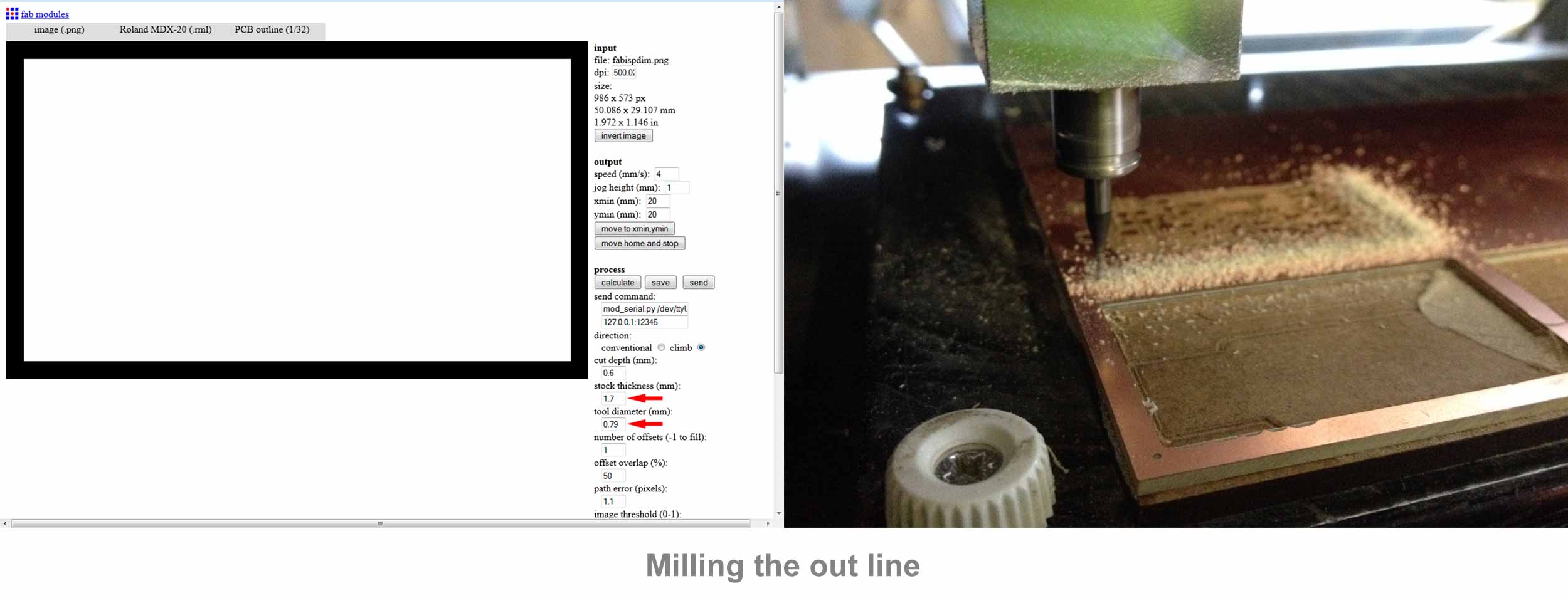
For milling the circuit I used the FabModule, I loaded the image in .png format and then I've selected the tool Roland MDX-20, the next step is to indicate if we are to mill the traces or the out line.
For the traces I used a 0.4mm milling cutter and I set the FabModule to go down just 0.1mm (copper thickness) in this way only removed copper without cut the board.
To mill board is necessary to change the milling cutter for a larger diameter (0.8mm) and set the depth of cut to 1.7mm in this way we ensure that the milling cutter will completely cutting the board.
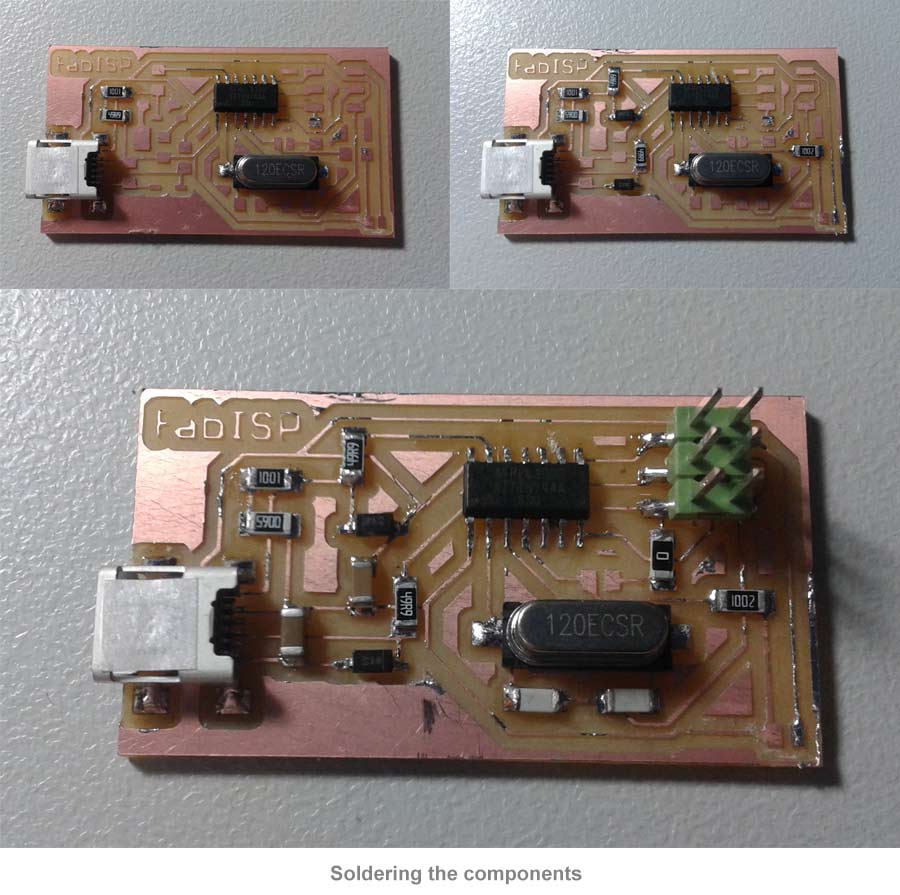
After milling the board and clean it to remove traces of glue and copper shavings, it's time to solder the components, for soldering SMD components, I use a low power soldering with fine tip. Something that also helps to make the welds is FLUX.
To sold the board I have chosen to put first the most complex components of welding (the chip and USB connector), followed by the components who don't hindering the following soldering.
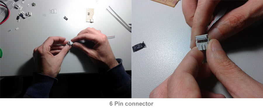
Another thing that I have to build is the ISP cable, for this I need only 20 cm flat cable connectors and 2 connectors. These connectors are crimped by pressure.
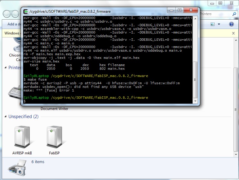
Programming the ISP programmer was not easy to understand at first, I found many and varied information some of which are contradicted, but at the end I found a very good tutorial here. Basically we must follow these steps to load the firmware to our AVR programmer:
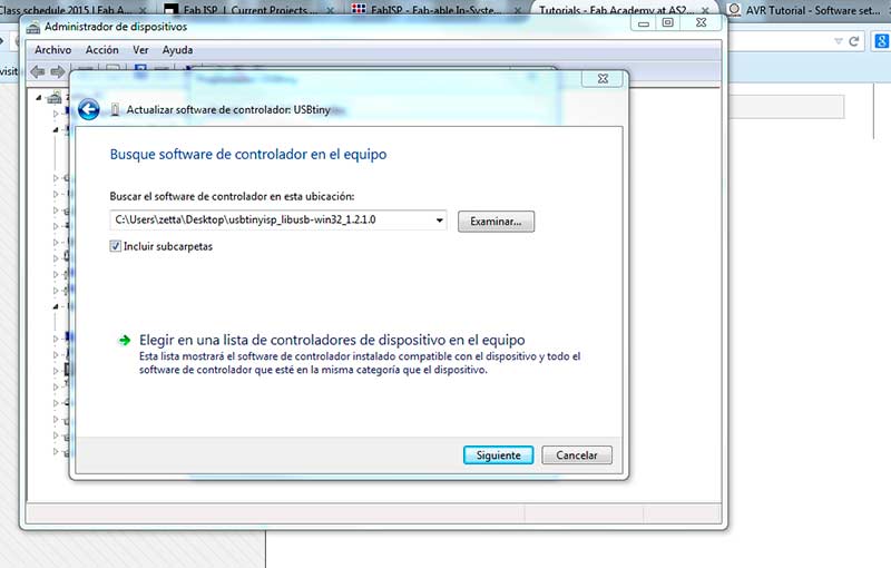
The first thing to do is install the drivers for our computer to recognize programmer, this is essential as we are going to use another programmer to program our programmer and our computer should know that we are connecting.
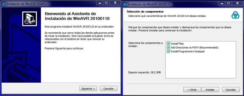
To load the firmware into the AVR programmer, You'll also need to install the development tools for AVR microcontrollers.
Once all the above steps are done, we just load the firmware. To do this, we must first be sure to join the jumpers on the board we want to program, if we do not, the plate will be write protected.
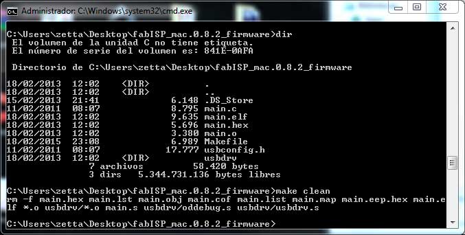
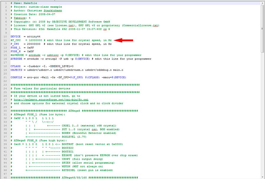
To load the firmware, unzip the folder to the desktop,Open the Makefile with Notepad++ remove the "#" in front of the line with "usbtiny" and add a "#" to beginning the line with the "avrisp2" in it to comment it out (save the Makefile).
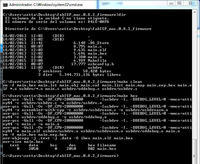
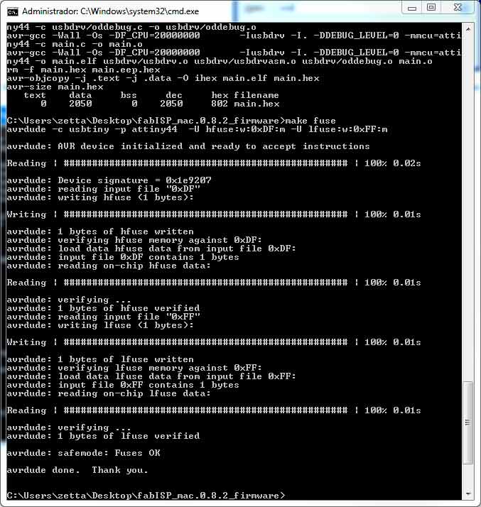
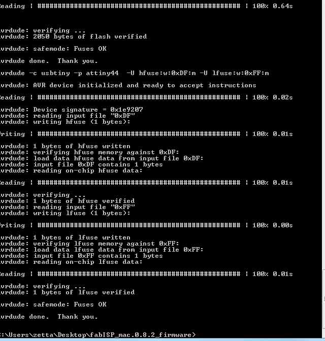
Before save the Makefile in it open the console and navigate to the location, then we just have to run these commands: