
My bird kit on MAKE! Sweet :)
Makezine covered my projects in an article about FabAcademy, wheyyyy! That's really cool hey.
http://makezine.com/2015/03/09/fab-academy-adventures-7-press-fit-construction-kits/We are getting 3mm heavy duty cardboard to work with this week. So first I made a test connection in Inkscape to find the right sizing for my model with this material. I made some models for 2.5-2.8mm wide notches so I could try some different fits in one go. For 3mm carboard, 2.5mm notches worked for this guy .
I tried doing some work with Inkscape. However after two clones Inkscape started guzzling up 99%-100% (thank you Acitivity Monitor) of my CPU which made it crash. I updated it to the latest version 0.91 (comes after 0.48 apparently).
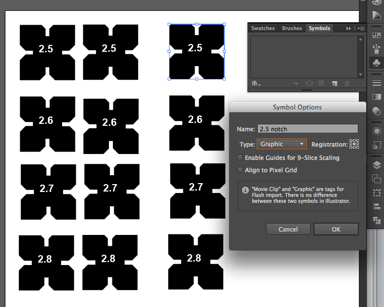
While Inkscape was reinstalling I tried working some more in Illustrator. Illustrator does have an option that resembles the "cloning" function Inkscape offers. You can transform an object or a group of objects into a symbol and then you reproduce instances of it. Modifying the root symbol later on consequently changes all instances of it.
The update solved the CPU problem and eventually I did my test pieces in inkscape. I used the blocking method and then when I was finished I created differences for all the elements to make it one shape. And then changed stroke to 0.001 pt and no fill. I had to do this because it turns out that our local lasercutter only likes files that consist only of 0.001-0.003pt outlines, if lines are thicker the machine will start engraving rather than cutting lines. It won't take black and white shape images, there's no fabmodule for ours unfortunately, so you have to deliver clean outline designs.
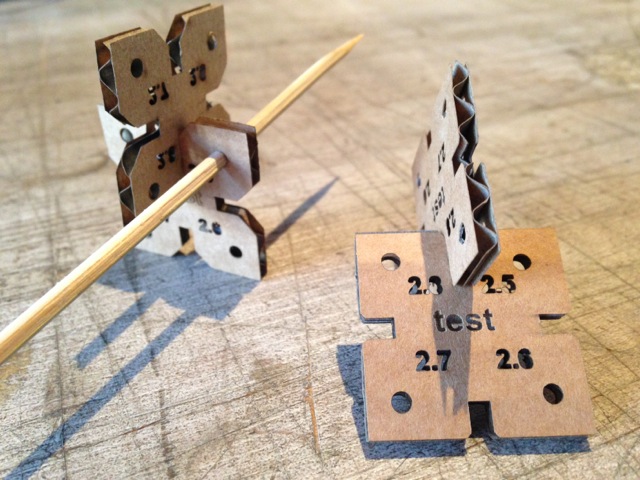
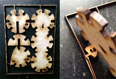
This whole process was very frustrating because my basic skills in Inkscape and Illustrator are near zero. Best vendetta to frustration is perhaps to them into a dummy tutorial: designing a testcut for your snapkit out of it!I created a connection with a deeper cut and one with a shallower cutout. I made pairs of squares where each side has a different width for the cutout (top=2.5mm, right=2,6mm, bottom=2.7 mm and left is 2.8mm) so I could test different widths efficiently. And I wrote these numbers on the piece itself - and outlined them - so I don't get confused afterwards.
I did test with notches as well as round cutouts for my skewers. Settings like speed=8 and power=100 were a good start. This worked beautifully, I set my notch to 2.5mm in my design and started designing some different basic elements.
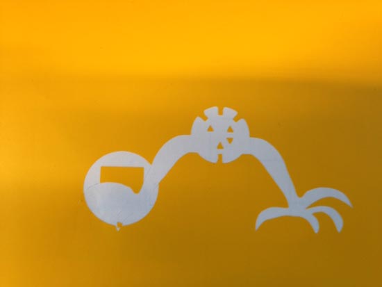
I used this fantastic construction kit by PenfoldPlant on Instructables for inspiration this week to create a whacky modifyiable construction kit with strange limbs.

I thought it would be wise to keep some symmetry in the distances so I also used a circle with a notch at every 45 degrees as a default that could be added to in different shapes and forms and extenstions. I used this tutorial to do it.
I wanted to test the designs of my basic elements as well, to see how they work together. But the machine did not laser anything, we tried a gazilion times. I cleaned the file, changed the colors, simplified the drawing. Made a test run. But each time my vectors weren't being cut. The machine just wanted to engrave something that wasn't there. Restarting the pc and the lasercutter didn't help. Drama. No test run for me....It's friday evening now and I out of options. Until Zaerc says: do you have the opacity on 100% for all shapes? Well yes, I think. But it's worth to take a look. Somewhere deep down in one of the paths (when you double click on shapes to go into the paths) indeed, all of them have some paths with 83% opacity, which is in fact GREY, so the lasercutter will want to engrave it.
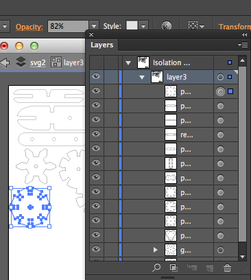
I cleaned up my entire file and tried to look for the mistake in Inkscape: it offers you many points where you can modify the opacity, not just for layers (like ILlustrator does), but also for each stroke, and each fill you apply to a path. This it where it went wrong once and the setting stayed that way for everything that came after Don't use opacity ever people! In the end I got it done though. Thank god. Everything fit, also with a 2.5mm notch. I decided that the wear of constructing and deconstructing can be compensated a bit with a narrower cut.
After all that I could finally focus on some creative designs. Rather than go deeply into technical fits for more elements I focused my time on creating weird shapes and additional decorative cutouts to achieve my desired steampunk look!
I made and saved several versions of the final design just in case something goes wrong in the manufacturing process: I can rule out some things quickly without losing machine time. I've made:
Inkscape on Mac is missing a few standard Windows controls like Alt. If you open the X11 preferences and enable Option keys send Alt_L and Alt_R it will recognize alt as alt so you can use Paste in Place quicker. Very useful for filling up your sheet with elements, and keeping them neatly aligned.
Inkscape has its own idea of default settings. David Mason sent these steps to the fabclass on how to change default settings of your inkscape files. Werk.
What I also found a super useful feature is the combination of the Freehand Lines tool (pencil), together with the simplify command (Ctrl+L). When you draw freehand lines you can simply close them by ending at the square that marks the starting point to create a closed line. Then when if you simplify it recreates the drawing with less control points each time you run the command. This makes your lines smoother and easier to manipulate. Great for dummies!
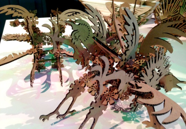
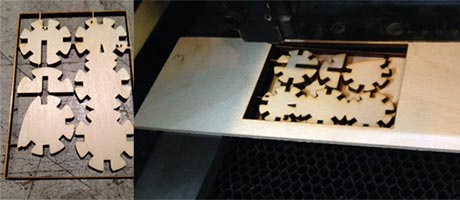
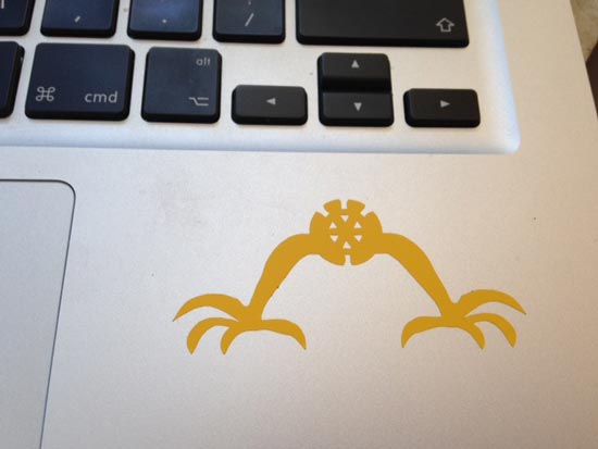
This is the final product (I made 4 bird war machines out of my kit). My settings were speed 6.6/power 100, and it took 1.5 hours.
While I was constructing I noticed two things: the detailed decorations weakens the cardboard and it's easy to break pieces. You have to work very patiently and try not to add too much pressure. Lasering it from plywood would be better for this.
Second is that some pieces didn't work at all, because they weren't symmetric with the other elements. Like the longer thick bars, the sizing was all off to make it fit with the round pieces. I also tried to make some moving parts as a bonus, with gears, using skewers as axis, but I didn't really think it through on how to construct that, and the holes for them were slightly too narrow so I really had to squish the elements onto them. Not so elegant and not so snap fit. Would be nice to do in the future, but anyways the basic snapfit kit works.
is the link to the svg file (decorated version) It will look blank but the content will show in inkscape if you set the > view to > outline.
My bird machines are sitting in the fablab right now and apparently they're catching quite some attention. So I decided to act on some encouragement and further develop the bird kit.
I made a small test using MDF (notches of 2.8mm are perfect for 3mm MDF, lasersettings speed 1.0, power 100) and found the following, I'm not entirely happy yet.
This also burned...I can sand the individual pieces and they looks great (see pic). But I will break the bridges of the sheet if I sand it while still together. Hmmm....Need to find another way to eliminate the burns.
Success! Beautifully clean backside without sanding. Speed 1.0, power 100.
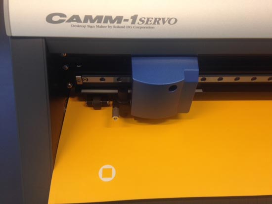
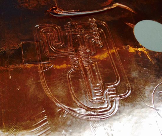
Where I work we have a Roland vinylcutter but with different software so I tried different methods as well. Here they work on a windows machine with a plugin for illustrator called CutStudio Plugin. This sends the vector file to the CutStudio software from which you can send the cut job. It's nice because Cutstudio has a pretty terrible interface that only allows you to handtrace bitmap files or draw very simple vector shapes.
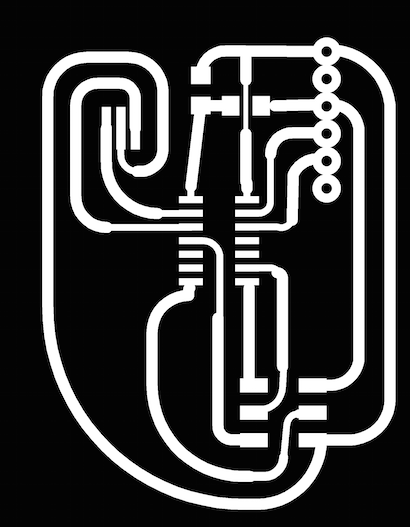
I was intrigued by the idea of making flexible circuits so used in week 6 I caught up with the vinylcutter to try it out. I used these resources to find out how and what:
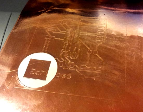
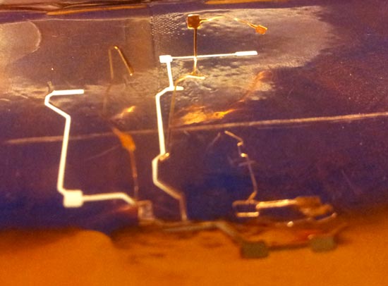
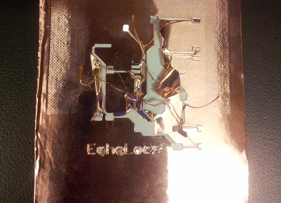
The last thing I tried was to redraw it AGAIN. I got rid of the button and the LED for the purpose of the exercise. Added a 0ohm resistor bridge (this resulted in an airwire but ok). And I rerouted all traces with 1mm, except where the clearance became a risk, there I had bits of 0.6 or 0.8mm but kept to a minimum. This will be my last shot at fame...here goes nothing.
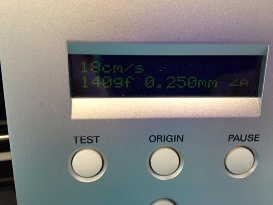
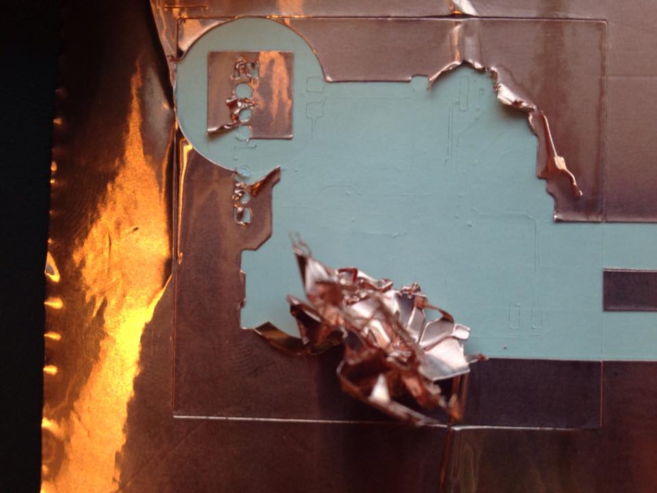
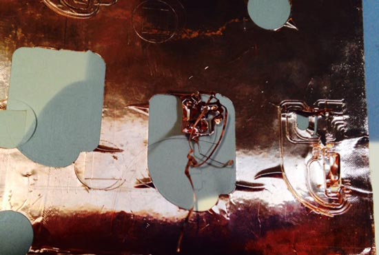
No successes later on either. I tried loads of settings, high low, fast, slow, everything. Cut on the left of the machine, cut on the right. Did multiple runs on the same route. Not of it worked. Either it didn't cut through or it flew up and wrecked the circuit. Zaerc is looking up his documentation to see how he did his successful vinylcuts and I'll take it from there..
