About my Final Project

This is the place that I will document everything about my final project for Fab Academy 2015.
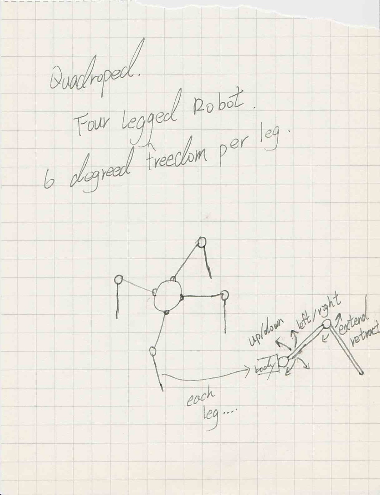
For my Final Project, I would like to mimic the art of Marionette (String Puppet) with a pair of Quadropods. Each of the Quadropod will have four similar legs, each leg will have 3 degrees of freedom.
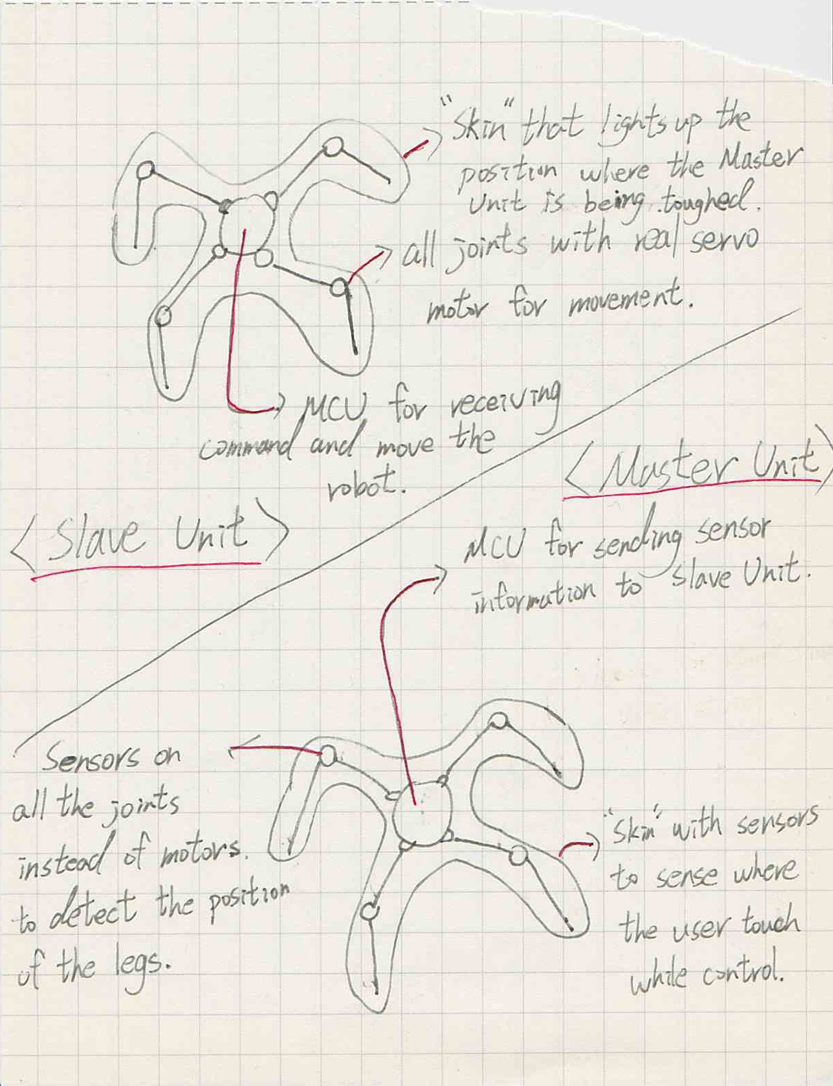
One Quadropod will be the control Unit, which represent the control stick and strings of a string puppet. Users manipulate the control Unit to send command to the other Quadropod to follow. For this to work, the control Unit will need sensors on each joints to sense the movement of the legs, and also a way to send command to the Performing Unit.
The other Quadropod with be the Performing Unit, which represent the puppet. The Performing Unit will receive the command send by the control Unit, and mimic the control Unit's movement. Enable for the Perofrming Unit to mimic movement, it will need servo motors, MCU, and battery.
One more thing I want to achieve is I have enough time, let the Performing Unit shows audiences where the performer is touching the Master Unit when controling it. For now, my idea is to have an array of touch sensors on the Master Unit, and have an array of LEDs on the Performing Unit. Whenever a touch sensor has been touched on the Master Unit, the LED that correspond to the location of the touch will light up on ther Performing Unit.
Extra Ideas, Design the control Unit a little different in a way that users can move it easily:
-like friction locking joints
-hooks on the bottom of the legs so its can stick to the ground when need to
-or maybe even attach points on legs for actual string control!
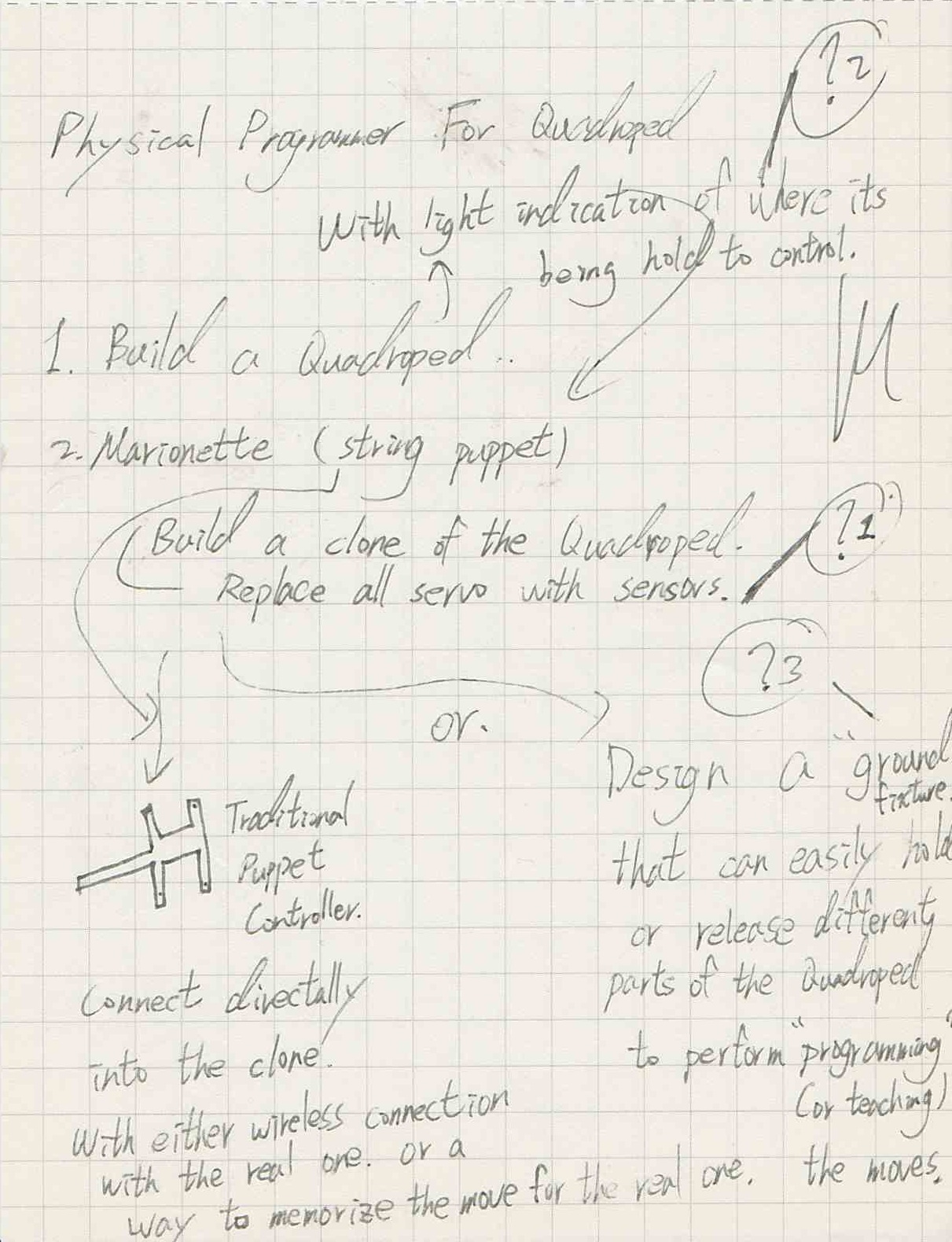
Final project proposal Sketch
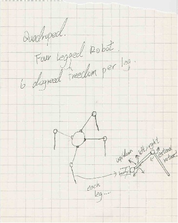
sketch of 6Dof Quadroped I had in my mind
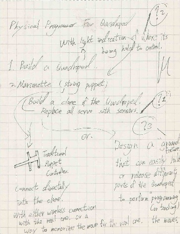
Brain storming of the control method to mimic string puppet
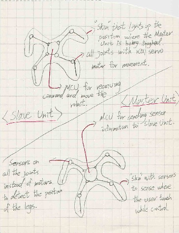
The differences between the two quadropeds
Pictures
A bit more about the project (May 16)
So far, I'm sticking with my original final project idea, an electronic marionette quadrope. To be more clearly, it's a quadroped with a wireless controller that looks like another quadroped, but with sensors on where the motors should be to measure angle of each joint.
I go the idea back when I was programming my friend's hexapod using an usual hexapod computer programmer. The process is more like making a stop motion animation: you move all the joint to the next posture, press record, next posture, record..... and play all the posture in the order you recorded, kinda boring. With my identical looking controller, control and program the quadroped became more like puppetry. Live interaction of the quadroped with the envirement became possible, more organic, and easier to do.
The components for my projects are pretty straight forward, one quadroped with 12 servos, 3 on each legs, a microcontroller, and another quadroped (the controller) with 12 potentiometers, 3 on each legs, a micrometer.
The main parts (legs) of both quadropeds will be 3D print and laser cut, but the shell of the body will be made out of either carbon fiber or glass fiber. (Carbon fiber will conduct electricity, which might be an bad idea for housing the electronic uless I insulate it first.)
The servos are xl-320 servo, which have 300 degres of movement, and controlled by TTL communication. To measure the angles of each joints on the controller, I decided on potentiometer bacause of their ease of use. However, I need to figure out an way to measure more than one potentiometer on one analog pin. So far, multiplaxing seems the way to go. All the parts roughly coast about 200usd since I got all the motors second hand.
The microcontroller on both quadroped and controller will be similar in components to the one I used in networking week, and use bluetooth to commnicate.
Right now, I roughly finished the programming of both microcontroller. Next thing in order is to design the dedicate PCB baord for both the uadroped and controller. After that, I just need to design the mechanical parts and make them into reality.
My goal is pretty simple, build the quadroped and controller, have the quadroped react acording to the movement of the controller. With enough time, I will make the controller with record and play back function.
BOM (May 16)
Puppy Quadroped:
- XL-320 Servo *12 (200USD)
- Bluetooth Module *1 (10USD)
- Microcontroller (with servo power distribution, servo signal, bluetooth connection, battery connection.)*1
- Battery *1 (5USD)
- 3D Printed Structure *1
- Molded Electronic Case *1
Controller Quadroped:
- Potentiameter *12 (12USD)
- Bluetooth Module *1 (10USD)
- Microcontroller (with potentiameter power distribution, Multiplexing pins, bluetooth connection, battery connection, buttoms for record/stop/playback.) *1
- Battery *1 (5USD)
- 3D Printed Structure *1
- Multiplexing chip *1 (5USD)
Things to do (May 16)
Done -Writing programs for both controller side and quadroped puppy side.
Half way there -Design the PCBs
-Test the servos, and bluetooth connection, and PCBs.
-Design the structure and 3D print it.
-Assemble both puppy quadroped and controller.
-Design electronic case and mkae it.
-Record a video of the projectworking.
electronics
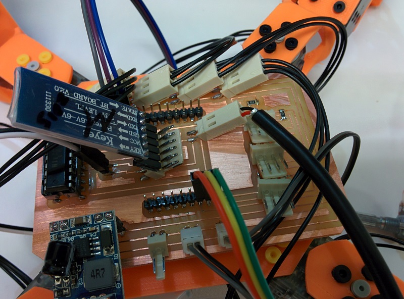
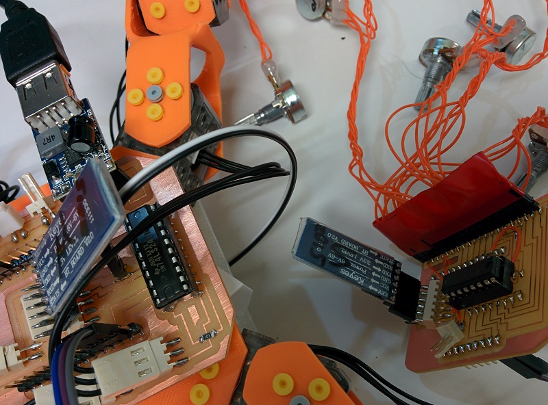
Both controlor unit and performing unit have a mcu main board, and a secondary shield for their own specific use. The control unit have a angel sensing shield that use analog multiplexer to read angle data from 12 potentiameters. The performing unit have a xl-320 servo shield that change the board signal into half-duplex signal for the servo motors to receive. Both shields have a bluetooth module, batteries, and a voltage regulator for powering the mcu.
I design both main board and shields using eagle, and milled them out a CNC mill.
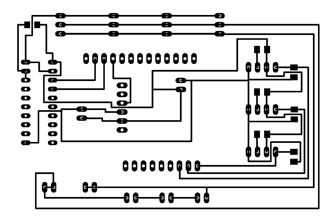
Angle shield schematic file!!!
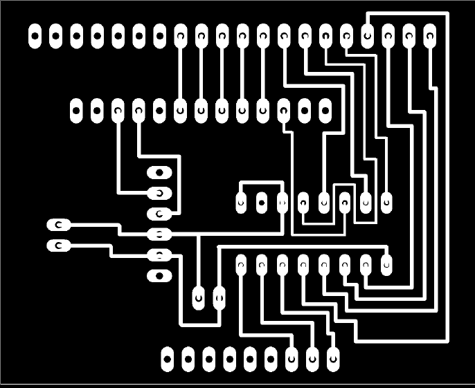
Xl320 servo shield board file!!!
Xl320 servo shield schematic file!!!
 Angle shield.
 Xl320 servo shield.
Programming
Programming of the boards are relative easy, since I already figured the hardest parts, aka motor control and bluetooth connection.
Both's board's programming is done in Arduino IDE.
Quadropod body design
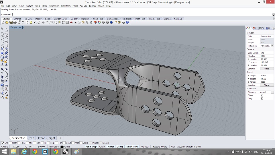
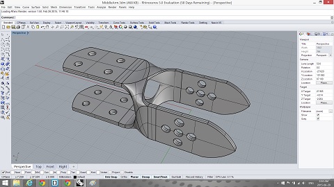
To design the performance unit's body, I use Rhino and try to draw some organic shape to chalange myself. The result is not bad considering it's my first time drawing shape like this. The body is than 3D printed out.
As for the control unit, I did it in 2D, and laser cut it out with wood. The reason is because the shape of potentiameters. Since potentiameters are not designed to use in this application, so the shape is not easy to be used as joints. Therefor I just made some simple wooden plate and hot glue to the potentiameters
Middle arm plate Rhino file!!!
Control unit laser cut file!!!
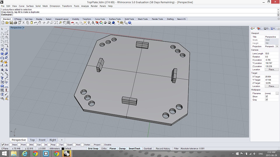
Top plate. The small tab is for holding the main mcu board and carbon fiber shell at the bottom of the quadropod for protection.
Upper ar
Middle arm
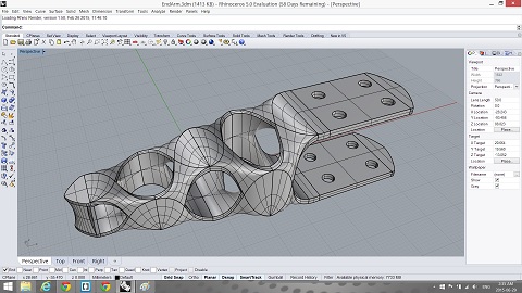
End arm
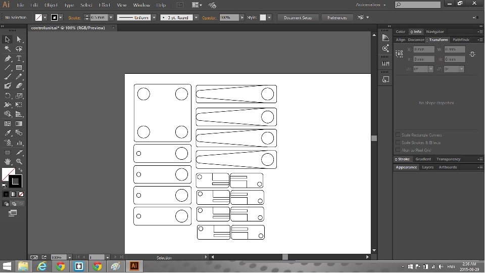
Control unit Drawing
Assembling!
"I love it when a plan comes together"
-John "Hannibal" Smith
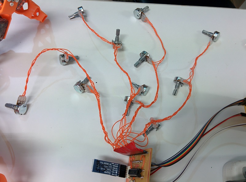
Soldering and cleaning the wires and potentiameters of the angle board.
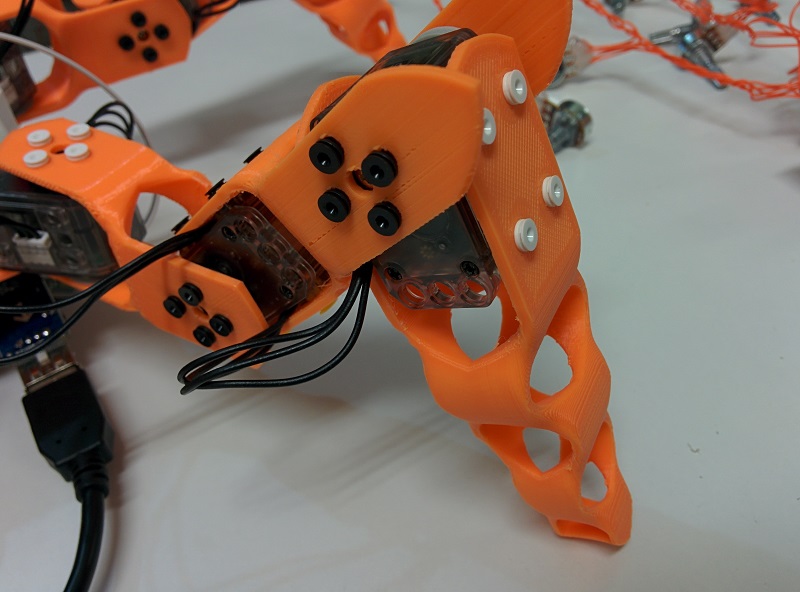
The performing unit's body is designed to be assembled with plastic revit I found is my part drawer. It's a bit fiddly, but works quite well to reduce the weight of the quadropod.
Fully assembled performing unit's body.
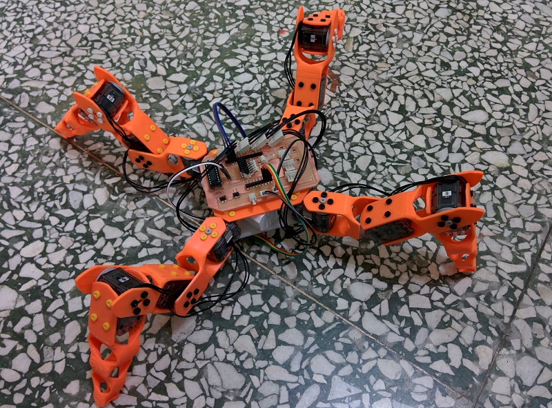
Wiring and connecting the xl-320 servo board, the main mcu board is on the botton side of the quadropod.
Doing a last minute check of the connection between bluetooth.
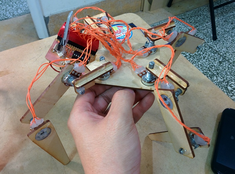
Fully assembled control unit. The wiring takes more space than I originally thought it would, hence the mess on the top. Main MCU board is also on the botton side of the body.
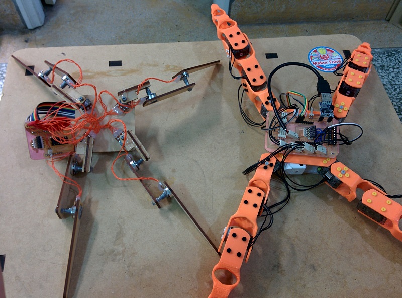
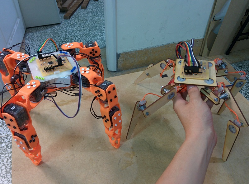
Performing unit (right), and control unit (left) doing a side by side comparison.

This is the bottom of the quadropod. The snap on carbon fiber shell protect the main mcu board from rubbing against the floor when performing.
Also, the batteries can be seem stored in the middle of the main plates.
The good, and the bad.
Here is the actually test of the synced movement.(Seriously, during this project, I constantly wish I have more than two hand...) Let's talk about the goods first. I found out by tweeking the delay between each motor commends, I can change the movement of the quadropod from really shakey to robot dance like. This is actually a really fun thing to control during performance, I just need to add an input to control the delay amount.
Also, I sort of figured out how to control the quadropod without the half-duplex circuit. Although the motor will constantly missing commend if controled in this way.
Here's comes the problems I encounterd. First, the battery is not powerful enough the move all 12 motors at once. Due to the nature of my control method, all 12 servos are constantly moving, and the fact that the weight of the quadropod are not always equally balanced on all four legs certaintly doesn't help. I'm looking into RC lipo batteries as alternate solutions right now, hopefully that will give the quadropod enough torque to totally mimic the movement of the control unit.
furthermore, I'm really not satisfied with the way I manage all the wires, especially the control unit. in fact, control unit is the first part of this final project that's gonna get redesigned after I'm ready to get back into it.
One last thing, enev though doing documentation has become less and less a trouble for me, I still need to improve doing this a great deal. I'm goin to try forcing myself to document all my projects from now on.
Final thought!
Well, this surely is a really challenging project for me. Not just I learned a lot of new skills during the process, but also chanllenge my time managing skill. Although there is a little accident of me frying the half-duplex conversion chip due to reversed battery polarity, most of the project comes along nicely. (And I will remember to add polarity protection everytime I design a PCB from now on.)
I managed to use as many skills I learned during the course as possible. Other than interface, this project contain almost every fabbing skills from fab academy.
For this project, I'm planning to further refine the electronics, and also add movement record ability to the performin unit. After that, a friend of mine will help me give it a puppet look and use this as part of his marionette performence. Than I will be able to see if this can actually add any new element to marionette interaction with audience. Which is the goal and reason of choosing this topic.
Anyway, this year's Fab Academy has being an wonderful ride for me. Looking forward to finally see all you awesome people in Fab 11 at Boston!
My Journey just begun. Cheers~
Ta~Da~