Wooden Structure
The plan is to modify the file for the wooden maze from week 8. I will need to use a thinner wood because now it is too heavy. Also there needs to be a place for the motors and a way to attach them to the board.
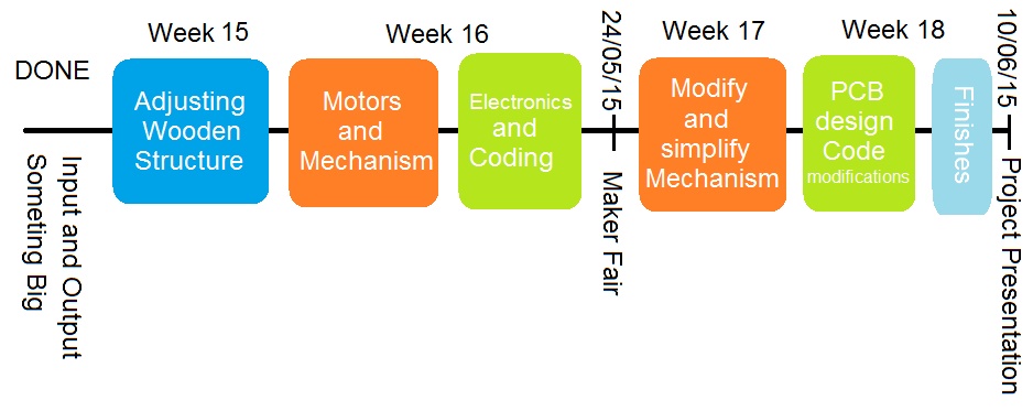
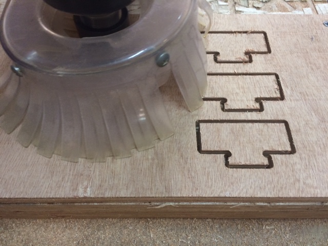
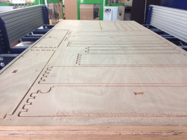
I made more test mills for the connectors to the board to find the exact size.
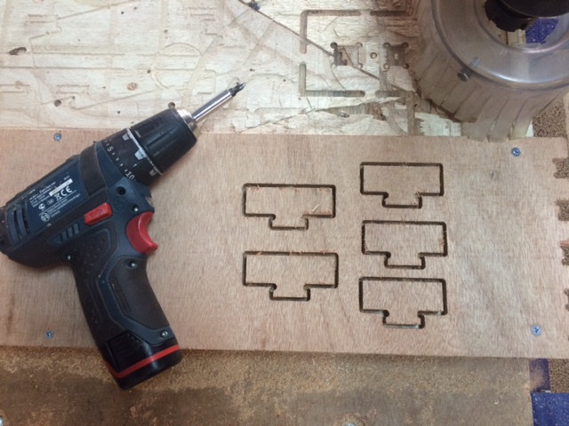
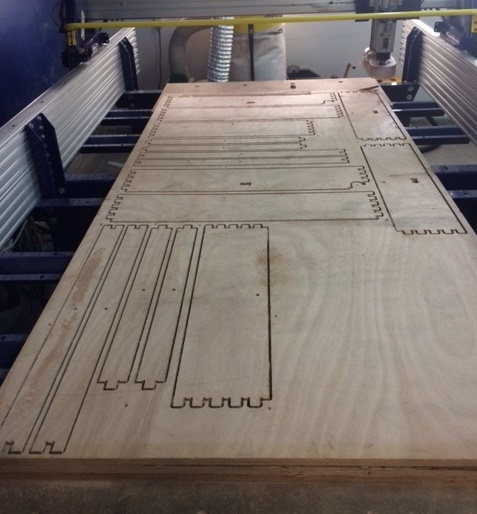
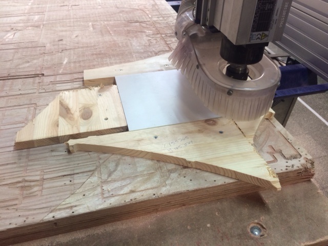
I milled the maze again and assembled it.
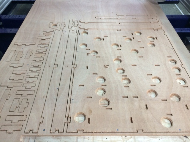
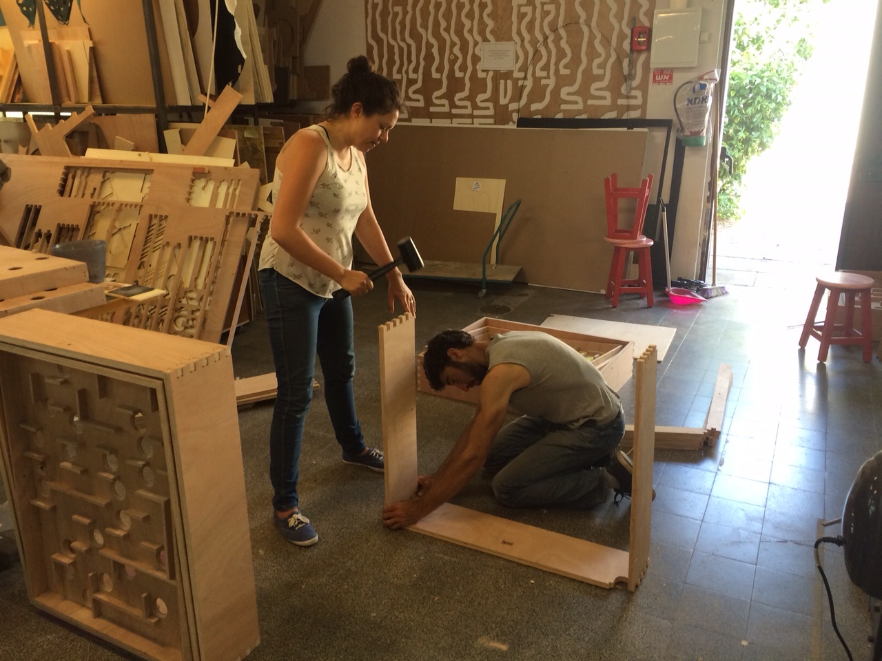
The outer frames turned out too thin so I decided to mill them again out of the 20mm plywood. For that to happen, I needed to modify the file again and make the connectors bigger.
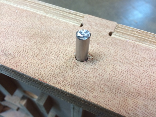
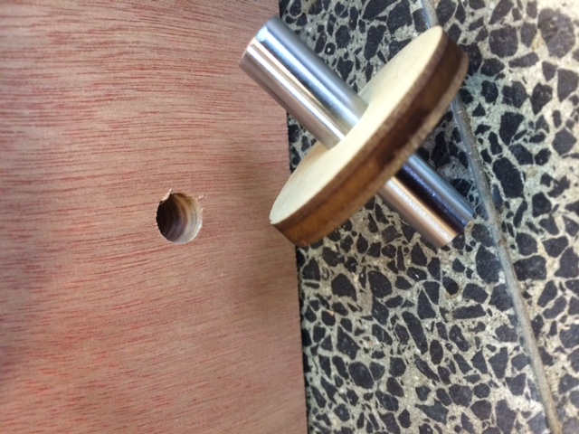
As bearings I used a 10mm steal rod like the one from week 8. For the inner bearings I cut them 35mm long and for the outer ones 45mm long, each rod has a 5mm wooden disc to operate as a spacer between the frames.
Mechanism
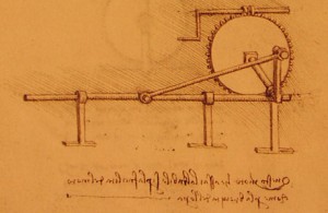
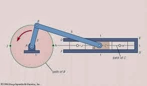
For the servo to move the board I needed to build a mechanism that changes circular motion to a linear one. Here are a few ideas I had:
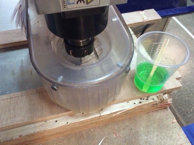
I used the Shopbot to mill aluminum arms for the servos. When milling aluminum you need to put some soap on it to reduce the friction and avoid heating of the endmill.
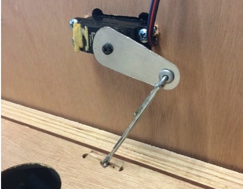
Connected the aluminum arms to the servos, used a metal rod from an old umbrella as another arm and connected it to the board. In the video you can see the maze controlled by an Arduino and performing the Sweep example for the two servos.
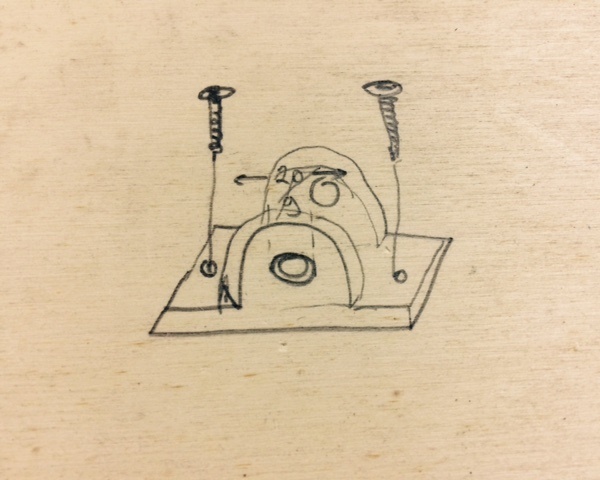
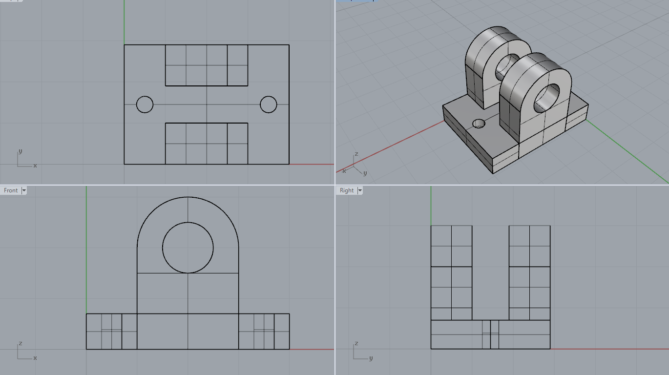
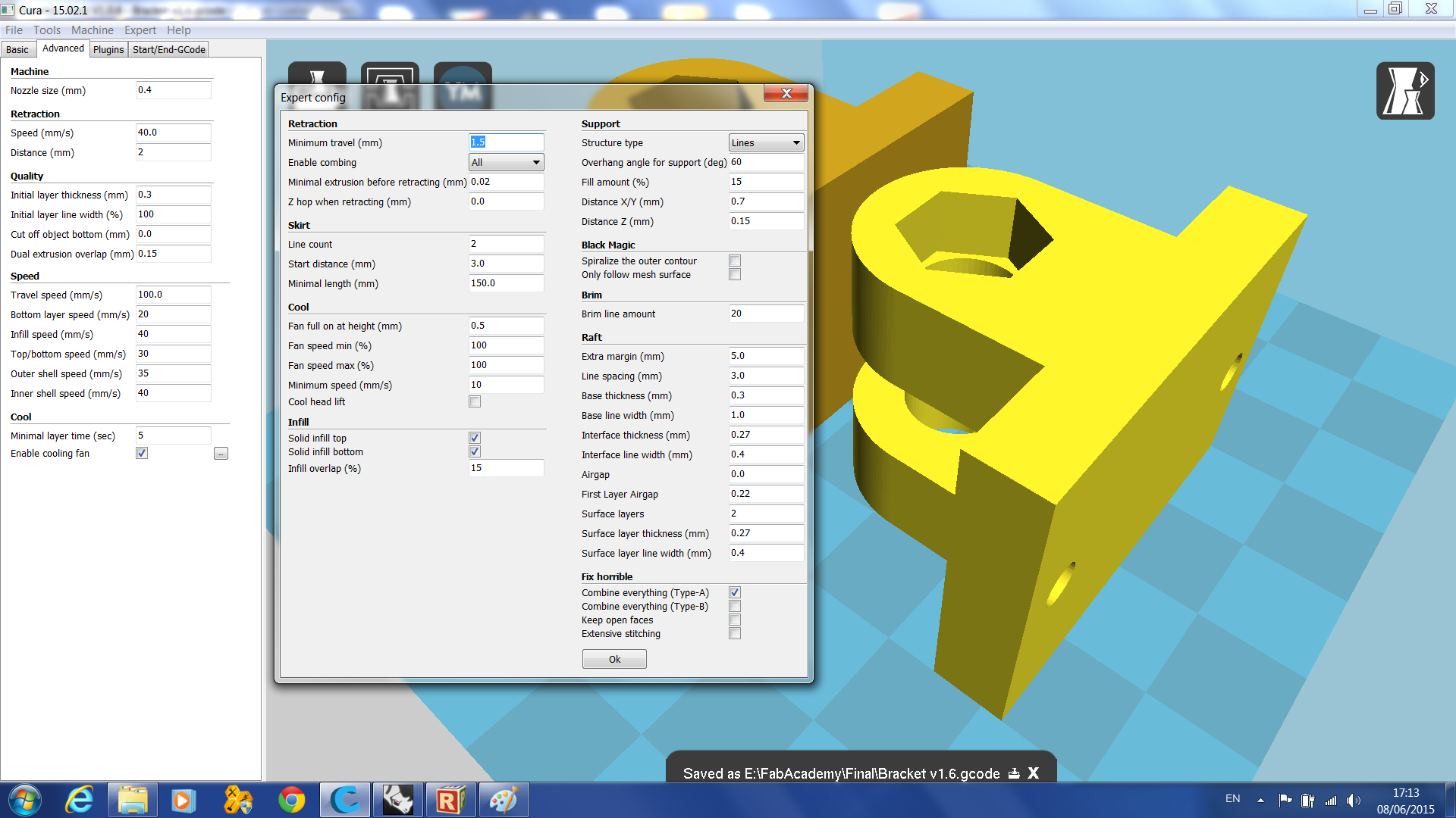
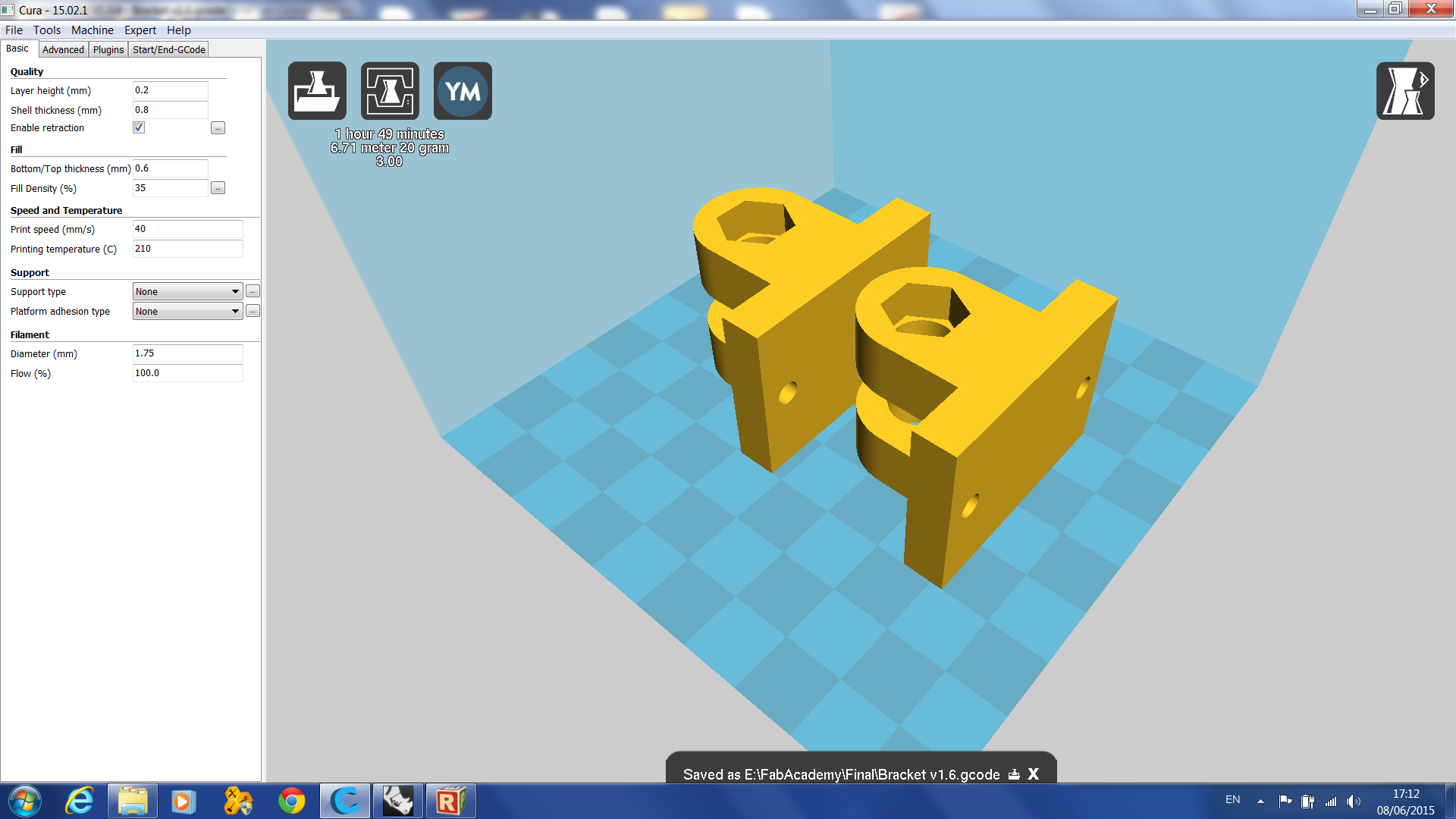
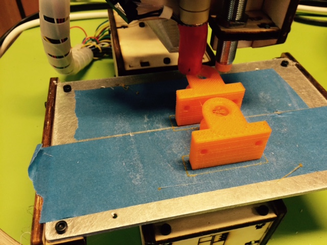
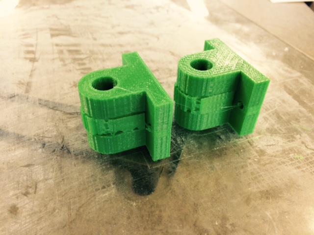
Next I needed to make the mechanism more durable, efficient and easy to fabricate. I printed a Bracket for the wooden plate.
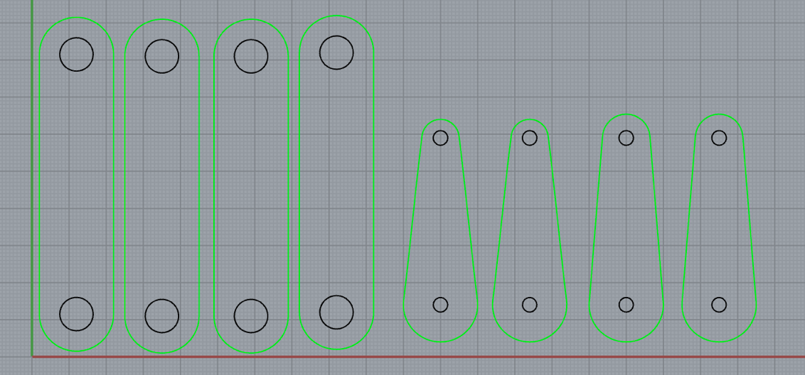
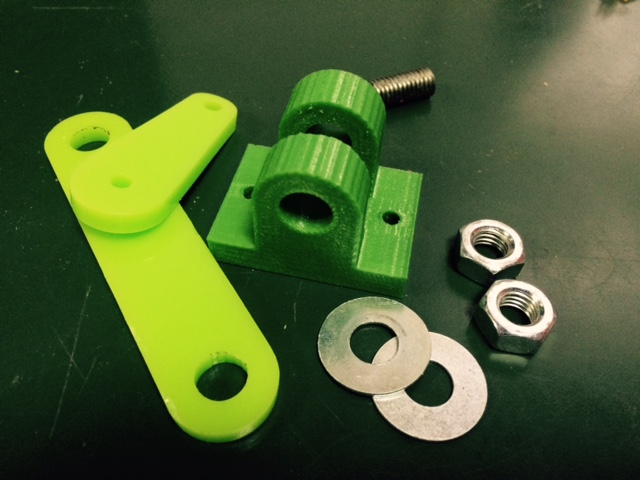
I replaced the aluminum arms with laser cutter 5mm plastic ones. These are the .DXF and .3dm files.
And used threaded rods, bolts and washers to assemble everything together.
Electronics
For the electronics I started with an Arduino Uno. I made a shield that connects to the Arduino with places for the wires to the servo motors and controllers. The Shield is soldered with 4 10K Resistors and one 0 OHM Resistor. This is the board I used for the maker fair. I had a problem with the power of the Arduino and had to keep it connected to my computed for it to work.
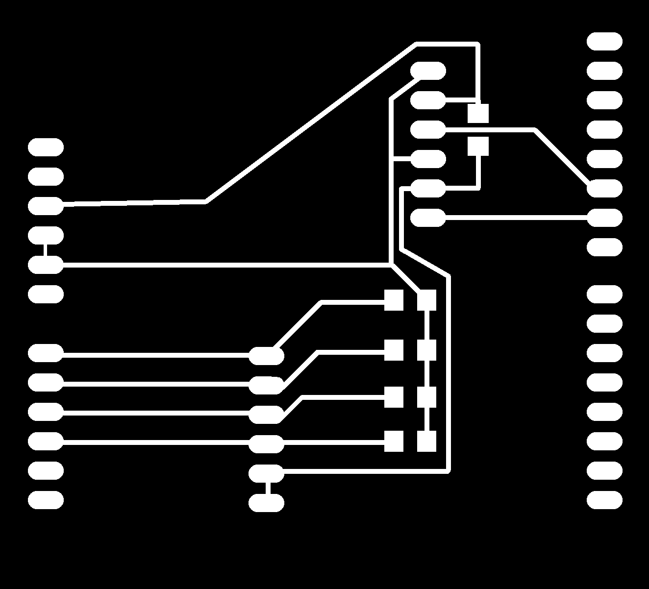
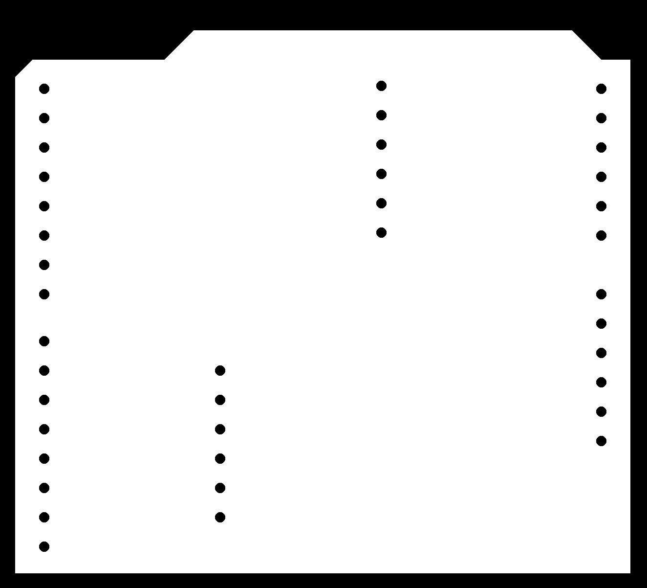
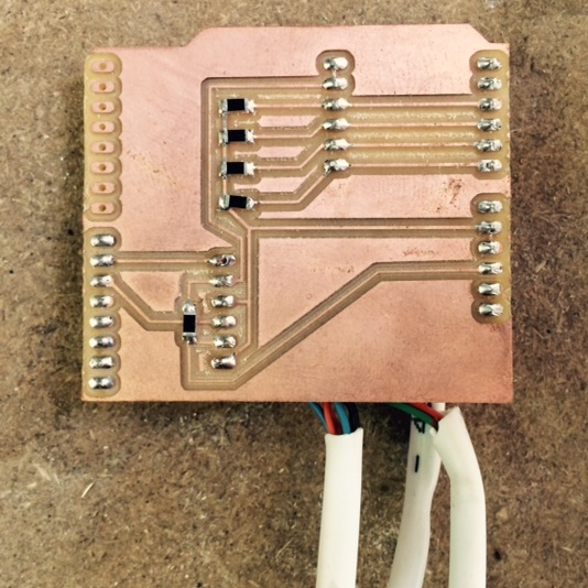
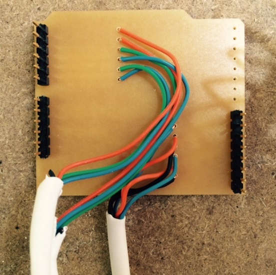
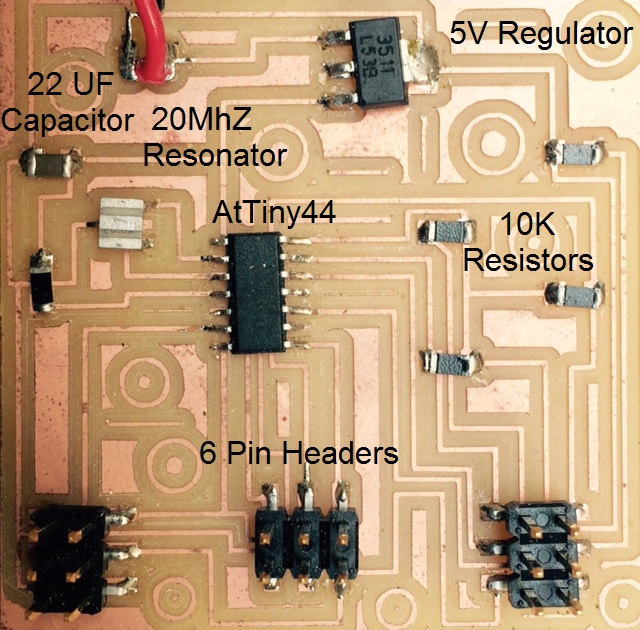
Next I made I made another board based on the AtTiny44 micro-controller. It has a 5V regulator and pin headers for the servos and controllers. You can download the Traces and Interior files
Programing
Generally the Code for the game is very simple. Each motor is has a range of 180 degrees. When positioned at 90 degrees the maze is leveled and the tilts back and forth are around that point. The input of each controller is from two photo-resistors. The difference between the two is the data needed to be translated to the angle between 0 and 180 degrees.
It took a while playing with the sensors and the serial monitor to determine the specific inputs. Using the Map function I translated the difference to angle. This is the Code for the Arduino.
Now I need to modify the code to work on the AtTiny44. In order to program the AtTiny44 with Arduino code you need to install the Tiny for Arduino. Download the attiny-ide-1.6.x ZIP file and install according to the tutorial in the High-Low link
The code for operating a servo motor with the AtTiny44 Chip is a bit different. Instead of using the regular servo.h library I used the SoftwareServo.h. After downloading the .zip file I opened the Sketch menu->Include Library->Add .ZIP Library and browsed to the downloaded zip file.
When using the SoftwareServo library you need to also use the SoftwareServo::refresh() function. This is the Code for the AtTiny44.
- © Or Shoval. All rights reserved.
- Design: HTML5 UP