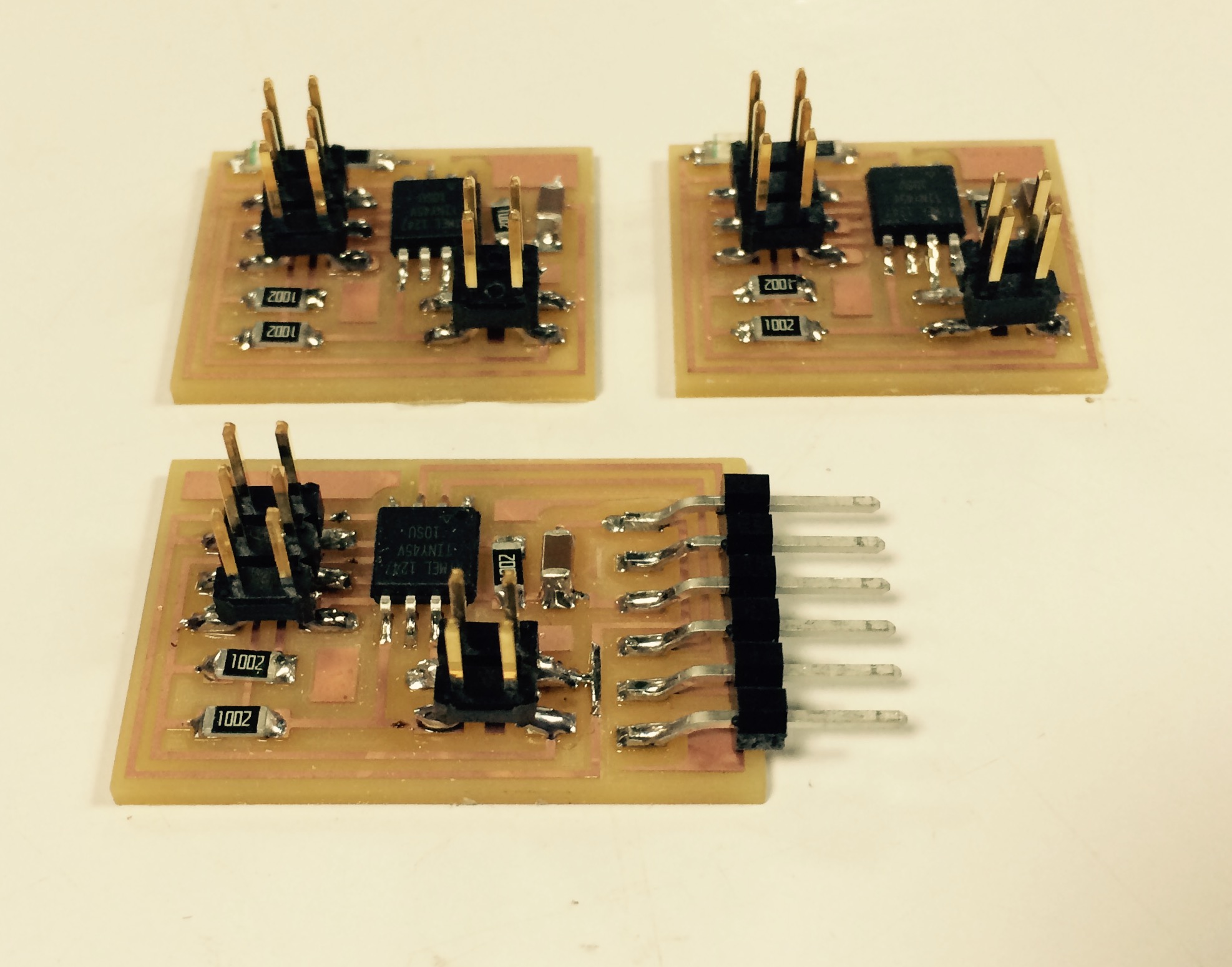
I started by milling and soldering three boards.
One board to operate as the bridge
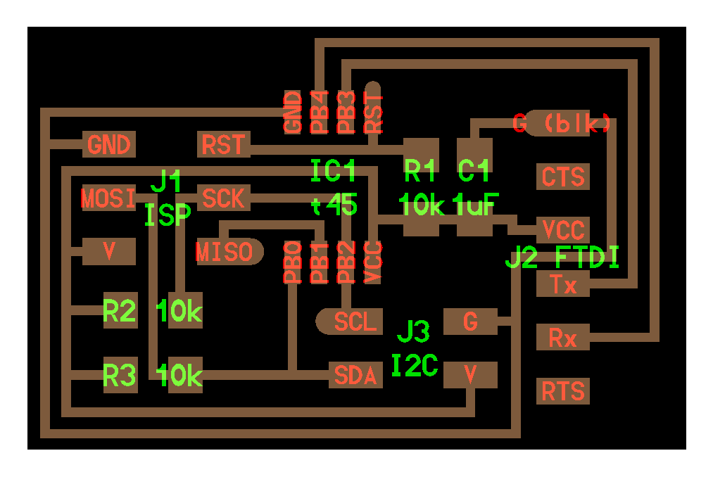

Two boards to operate as nodes.
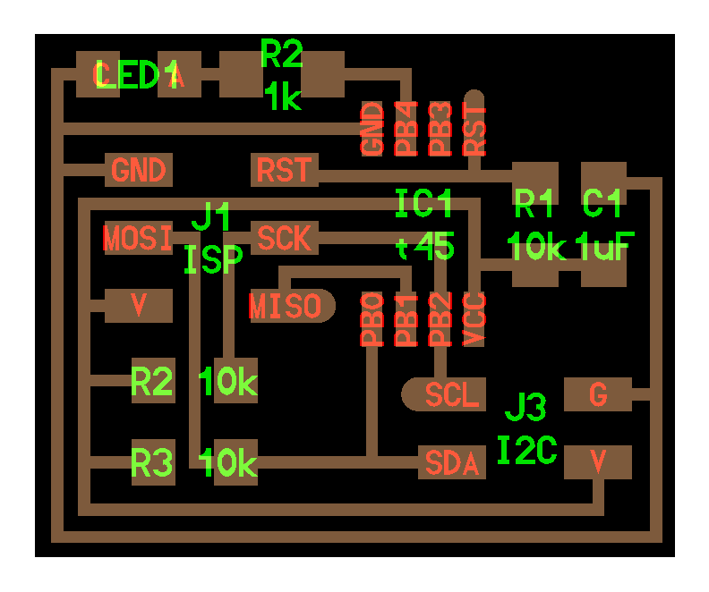

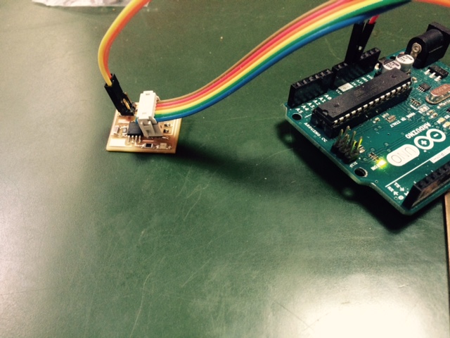
I used Arduino UNO as ISP to program. First step was to check and identify the pins for communication and LED and the second step was to perfect the code and get a response from the serial port.
I programmed the nodes to blink for a second when called upon by ID numbers 1 or 2.
Serial communication needs a special library for the AtTiny44 micro-controller. I used the SoftwareSerial.h after downloading the .zip file I opened the Sketch menu->Include Library->Add .ZIP Library and browsed to the downloaded zip file.
The codes for the two nodes are similar with one difference of ID. This is the code for Node 1.
In the first/left video is the board just after I programmed its LED to blink. In the second/right video is me controlling the LED with the Arduino Tx Rx pins.
For the bridge I used the SoftwareSerial function twice. Once for the communication between the computer and the bridge and again for the communication between the bridge and the nodes.
It took a while to get the pin numbers correct but eventually it worked. This is the code for the Brigde.
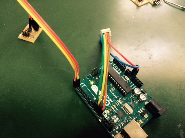
I made a 3 connector bus cable for power and communication, connected the two nodes and bridge and used an FTDI cable for serial monitor communication. In the next video you can see me turning on the LED of each node by calling on its ID on the serial monitor.