{ Fab Academy 2015 : Koichi Shiraishi }
{ Home } { Final project } { Class } { Fab Academy }
- Week 13: Networking and Communications -
Weekly Assignment
- design and build a wired &/or wireless network connecting at least two processors
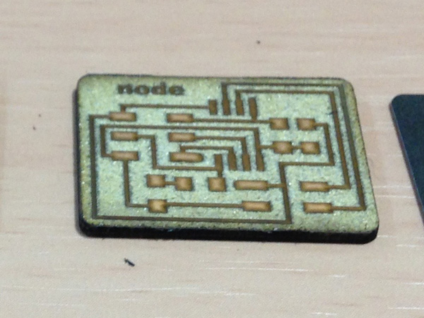
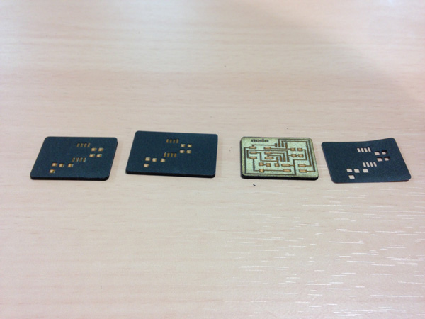
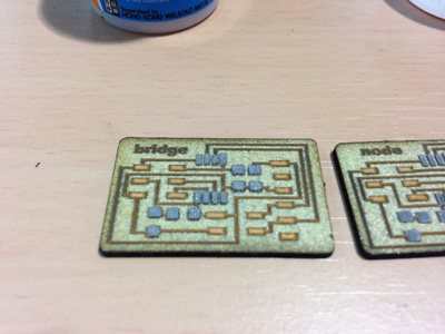
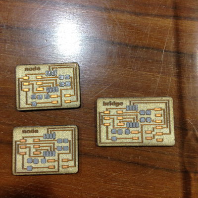
1: Engraving boards
I used the laser again to make the boards. I wrote How to generate a circuit board by laser. You can use “my site (Week 10)” as reference.
It was easy and smoothly by past parameter.
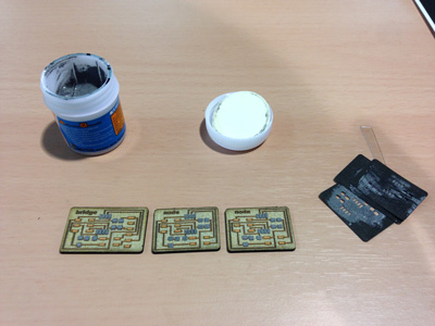
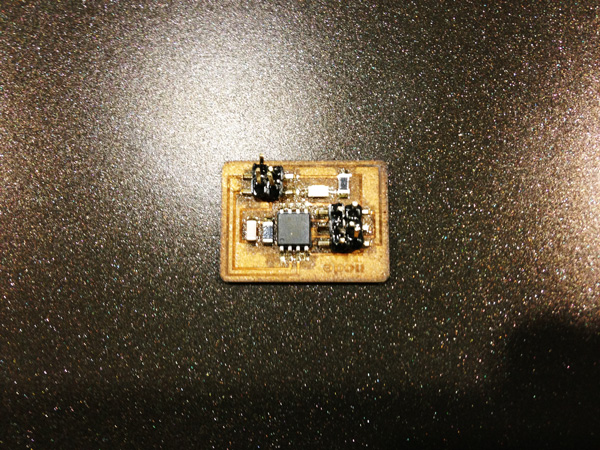
2: Soldering
I need to make few same boards in this week, therefore I decided to use the cream solder. But I do not have reflow oven. Consequently, I utilized a “Hot plate” which is used in cooking. It is very cheep one(about ¥2,400).
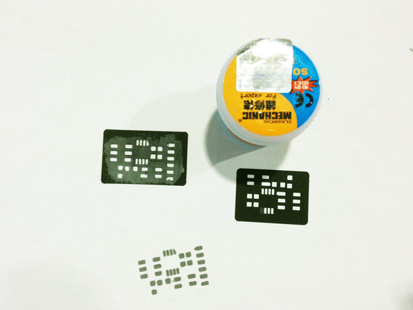
MAKING MASKS
Masking data is generated by eagle. Generating method is explained in this site(in Japanese).
The mask usually is made by vinyl cutter, however I think using laser is better way for delicate pattern. Consequently, I tested a few materials by laser.
1)synthetic paper
I used the “YUPO(???mm).” I tried several Parameters again to again. However it was not finished well. Principal ingredient of “yupo” is Polypropilene. It has high coefficients of thermal contraction. Consequently, I changed a material.
2)cotton paper
I tested the cotton paper(t???mm). It was finished better than a “yupo.” I decided to use this.
| Processing | Laser type | Power | Speed | Frequency | Path |
|---|---|---|---|---|---|
| Pattern cutting | C)2 laser(60W) | 10% | 1% | 6000Hz | 3 times |
| Outline cutting | CO2 laser(60W) | 12% | 1% | 1000Hz | 1 time |
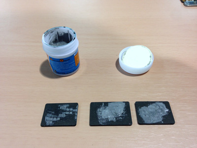
SQUEEGEEING
I used the video below as reference.
- Spray a spray adhesive to back of the mask for fixing.
- Take slight solder from the bottle.
- Squeegeed carefully. Fill The mask hole by cream solder.
- Replace the mask slowly
- Put the parts. Be care orientation of the parts.
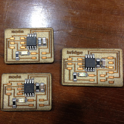
HEATING
I used the diagrams below as reference.
I did not have a thermocouple. therefore I adopted as a simplified method in this case, I measured the time.
I checked short circuit around a IC.
Failure case
The pins melted on the Hot plate. Consequently, I soldered the pins by a iron after a reflow.
3: Burning the program
I downloaded the "hello.bus.45.c" and "makefile" code from here.
I used this site as a reference.
I need to change the line below in the hello.bus.45.c code. In my case, I defined the bridge as '0', one node as '1', and another node as '2'.
#define node_id '0'
I used “AVR ISP” to burn the code.
I connected the FTDI header to the bridge boards, and made the serial connection between the boards with a 4-pin serial cable. After then, I connected ISP to each circuit. I burned the code which was saved each address.
terminal
Move to "hello.bus.45.c" and "makefile" directory. And Type below.
sudo make -f hello.bus.45.make program-avrisp2
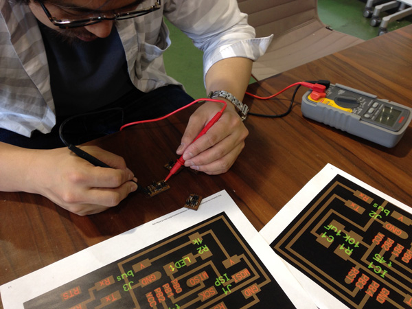
Testing
After burning the code, I tested network communication.
- Open a Arduino IDE
- Open the serial monitor from the "Tools" menu > serial monitor
- Make sure the baud rate is set to 9600.
- Enter number of a note (pick a number) into serial monitor - press the "enter" key or the "send" button on the serial monitor.