{ Fab Academy 2015 : Koichi Shiraishi }
{ Home } { Final project } { Class } { Fab Academy }
- Final project -
desktop documentation device
Project proposal(May/2015 wrote )
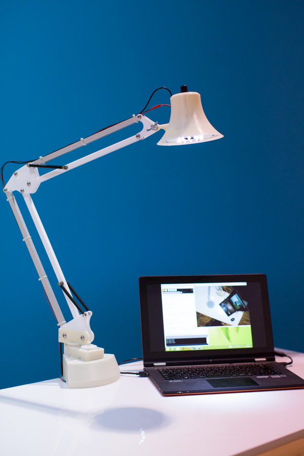
I will make "desktop documentation bot."
It looks like “adjustable light” on desktop. It records pictures automatically by camera device which assembled at hood.
Making motive
Weekly documentation is very important. It needs many pictures.
However, I often forgot taking pictures while focusing on my assignment.
Therefor, taking pictures each step is too difficult for me. Because, my arms are busy to making.
I look up to my partner take fully recording on my desktop.
It is my solution.
System
1: motion detection sequence
DDB(Desktop documentation bot)detects motion by a camera device inside hood. A program elicits center of motion from comparing previous situation with current situation.
2: Moving light sequence
DDB expand or contract and rotate for following the center point. The light adjust the point to center of the screen. After then, it takes pictures.
The users only turn on a switch, the documentation is made automatically.
Drawings
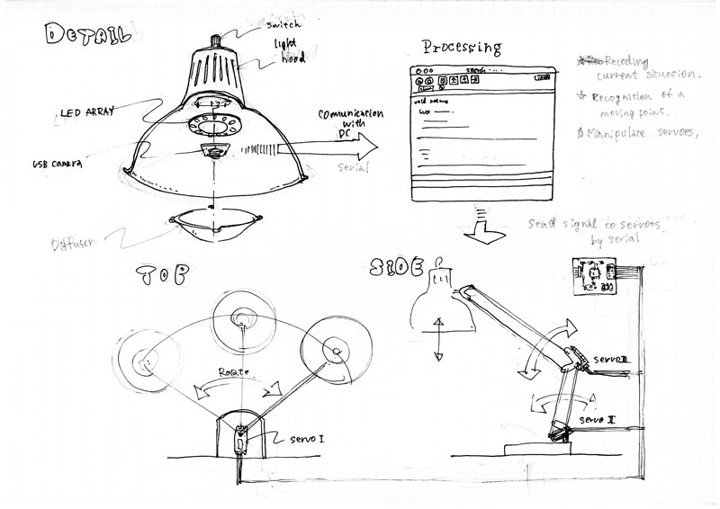
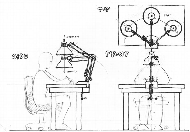
Check a scale
I studied scaling by 2D model.
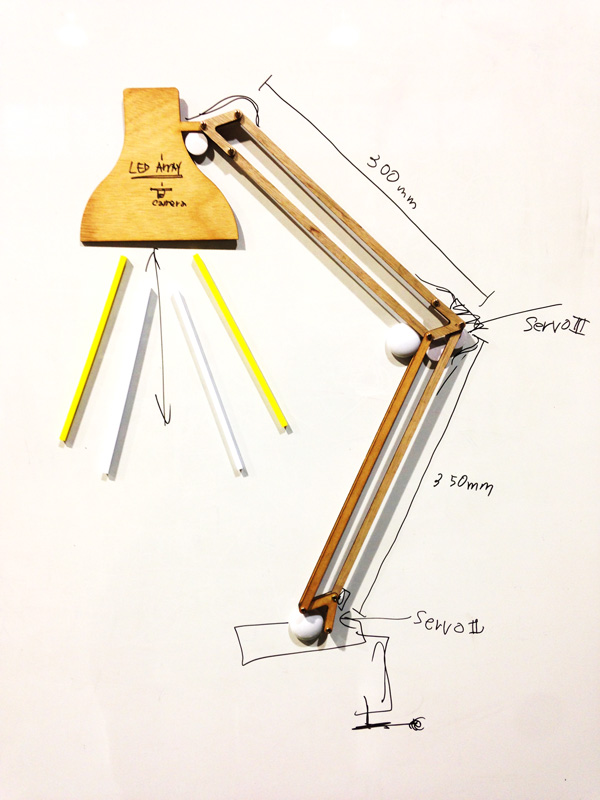
Developed motion detection
I developed motion detection code by Processing. It detect a center of motion balance.
Processing code
						import processing.video.*;

						String TARGET_CAMERA = "name=USB_Camera #2,size=960x540,fps=30";

						int WIDTH = 960;
						int HEIGHT = 540;

						float alpha = 0.03;
						int mPrevX = WIDTH / 2;
						int mPrevY = HEIGHT / 2;

						// Variable for capture device
						Capture video;
						// Previous Frame
						PImage prevFrame;
						// How different must a pixel be to be a "motion" pixel
						float threshold = 50;

						void setup() {
							size(WIDTH, HEIGHT);

							// cameras
							String[] cameras = Capture.list();

							if (cameras.length == 0)
							{
								println("There are no cameras available for capture.");
								exit();
							}
							else
							{
								println("target: " + TARGET_CAMERA);

								for (int i = 0; i < cameras.length; i++)
								{
									println("cameras[" + i + "]: " + cameras[i]);
									if (cameras[i].equals(TARGET_CAMERA))
									{
										// The camera can be initialized directly using an
										// element from the array returned by list():
										video = new Capture(this, cameras[i]);
										video.start();
										println("i can find the target camera.");
										break;
									}
								}
							}

							//video = new Capture(this, width, height, 30);
							// Create an empty image the same size as the video
							//prevFrame = createImage(video.width,video.height,RGB);
							prevFrame = createImage(WIDTH, HEIGHT, RGB);
							}

							void draw() {

								// Capture video
								if (video.available()) {
									// Save previous frame for motion detection!!
									prevFrame.copy(video, 0, 0, WIDTH, HEIGHT, 0, 0, WIDTH, HEIGHT);
									// Before we read the new frame, we always save the previous frame for comparison!
									prevFrame.updatePixels();
									video.read();
								}

								loadPixels();
								video.loadPixels();
								prevFrame.loadPixels();

								int sumX = 0;
								int sumY = 0;
								int countBlack = 0;

								// Begin loop to walk through every pixel
								for (int x = 0; x < video.width; x ++ ) {
									for (int y = 0; y < video.height; y ++ ) {

										int loc = x + (y * WIDTH);            // Step 1, what is the 1D pixel location
										color current = video.pixels[loc];      // Step 2, what is the current color
										color previous = prevFrame.pixels[loc]; // Step 3, what is the previous color

										// Step 4, compare colors (previous vs. current)
										float r1 = red(current); float g1 = green(current); float b1 = blue(current);
										float r2 = red(previous); float g2 = green(previous); float b2 = blue(previous);
										float diff = dist(r1,g1,b1,r2,g2,b2);

										// Step 5, How different are the colors?
										// If the color at that pixel has changed, then there is motion at that pixel.
										if (diff > threshold) {
											// If motion, display black
											pixels[loc] = color(0);

											sumX += x;
											sumY += y;
											countBlack++;

										} else {
											// If not, display white
											pixels[loc] = color(255);
										}
									}
								}

								updatePixels();

								int aveX;
								int aveY;

								if (countBlack != 0) {
									aveX = sumX / countBlack;
									aveY = sumY / countBlack;
								}
								else {
									aveX = WIDTH / 2;
									aveY = HEIGHT / 2;
								}

								//println(sumX, sumY, countBlack, aveX, aveY);

								int mCurX = (int) ((1 - alpha) * mPrevX + alpha * aveX);
								int mCurY = (int) ((1 - alpha) * mPrevY + alpha * aveY);

								fill(255,0,0);
								ellipse(mCurX, mCurY, 10, 10);

								// set previous point
								mPrevX = mCurX;
								mPrevY = mCurY;

							}
Make stepper circuit
I made a stepper circuit to connect laptop by ftdi.
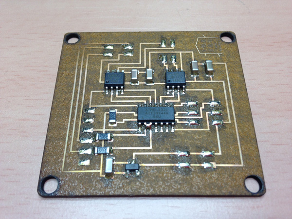
Engraved data
Direction control test with Processing & Arduino IDE.
I developed two codes. The first one is sending simple protocol by “Processing.” The other is receiving protocol by “Arduino IDE.”
Protocol
Right = 0 Left = 1
It had problem. The 8 port did not work. I changed the port number, and checked it. After burning a new code, It worked.
The code was not fault. I guess It was broke when I soldered wire.
Tested codes
1: Processing
					import processing.serial.*;

					Serial myPort;  			// The serial port

					String command = "";

					void setup() {
  												// List all the available serial ports
  						println(Serial.list());
  												// Open the port you are using at the rate you want:
  						myPort = new Serial(this, Serial.list()[5], 9600);
					}

					void draw() {

						 text(command, width/2, height/2);
					}

					void keyPressed() {
 						if (key == CODED) {
    						if (keyCode == RIGHT) {
      							command = "Clockwise";
      							println("Clockwise");
      							myPort.write(0);
    						} else if (keyCode == LEFT) {
      							command = "Counter clockwise";
      							println("Counter clockwise");
     							myPort.write(1);
    						}
  						}
					}
2: Arduino IDE
					#include
					#include

					const int rx=9;
					const int tx=8;

					int rotate = 0;

					SoftwareSerial mySerial(rx,tx);

					const int stepsPerRevolution = 25;  // change this to fit the number of steps per revolution
														// for your motor

														// initialize the stepper library on pins 0 through 4 except 2:
					Stepper myStepper(stepsPerRevolution, 0, 1, 3, 4);

					void setup() {
  														// set the speed at 60 rpm:
  						myStepper.setSpeed(60);

  						pinMode(rx,INPUT);
  						pinMode(tx,OUTPUT);
  						mySerial.begin(9600);
					}

					void loop() {

  						if (mySerial.available() > 0){
    					rotate = mySerial.read();

   							if (rotate == 0){
      							myStepper.step(stepsPerRevolution);
      							delay(15);
   							}else if (rotate == 1){
      							myStepper.step(-stepsPerRevolution);
      							delay(15);
   							}

  						}

					}
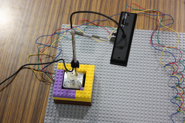
Control stepper with Processing
I tried to control a stepper with Processing. It is a super rapid prototype.
processing code
					// For video capture.
					import processing.video.*;
					// For serial communication.
					import processing.serial.*;

					// Screen size
					int WIDTH = 640;
					int HEIGHT = 480;

					// Capture device
					Capture video;

					// Camera name
					//String TARGET_CAMERA = "name=USB_Camera #2,size=960x540,fps=30";
					//String TARGET_CAMERA = "name=USB HD Webcam,size=640x480,fps=30";
					String TARGET_CAMERA = "name=USB_Camera,size=640x480,fps=30";

					String portName = "COM8";

					// Previous info.
					PImage prevFrame;
					PVector prevFocus = new PVector(WIDTH / 2, HEIGHT / 2);

					// Serial connection
					Serial serial;

					// Parameters.
					// Threashold for the motion detection
					float thColor = 70;
					// Threashold for moving
					// Center of the moving should be farther than thDistance from the center of screen.
					int thDistance = 100;
					// Threashold for moving
					// Moving pixel should be more
					than thCountMove.
					int thCountMove = 1000;
					// How fast the focus moves
					float moveRate = 0.03;

					// Serial setting.
					// Interval (ms) for sending orders.
					int sendInterval = 300;
					// Previous time (ms)
					int prevSendTime;

					void setup() {
					  // Screen size
					  size(WIDTH, HEIGHT);

					  // Set current time
					  prevSendTime = millis();

					  // Setup serial port.
					  serial = new Serial(this, portName, 9600);
					  serial.clear();

					  // Initialize and start video
					  if (!initVideo())
					  {
					    exit();
					  }

					  // Initialize the previous frame
					  prevFrame = createImage(WIDTH, HEIGHT, RGB);
					}

					void draw() {

					  // If video is not avairable now, just skip all.
					  if (!video.available()) {
					    // This happens many times.
					    return;
					  }
					  // Read the current video.
					  // The video works as a PImage.
					  video.read();

					  // Show current video image.
					  image(video, 0, 0);

					  // To calculate the center.
					  int sumX = 0;
					  int sumY = 0;
					  int countMove = 0;

					  // Loop to walk through every pixel
					  for (int x = 0; x < WIDTH; x++) {
					    for (int y = 0; y < HEIGHT; y++) {
					      // Calculate the index of the pixcel from x and y
					      int idx = x + (y * WIDTH);
					      // Capture the color to compare
					      color cColor = video.pixels[idx];
					      color pColor = prevFrame.pixels[idx];

					      // Compare colors
					      float cRed = red(cColor);
					      float cGrn = green(cColor);
					      float cBlu = blue(cColor);
					      float pRed = red(pColor);
					      float pGrn = green(pColor);
					      float pBlu = blue(pColor);
					      float diff = dist(cRed, cGrn, cBlu, pRed, pGrn, pBlu);

					      // If the colors are different enough, the pixel indicates movement.
					      if (diff > thColor) {
					        // Calculate the center of the movement.
					        sumX += x;
					        sumY += y;
					        countMove++;
					      }
					    }
					  }

					  // Focus point.
					  PVector curFocus = new PVector(WIDTH / 2, HEIGHT / 2);

					  // Center point of the movement.
					  PVector mCenter = new PVector();

					  if (countMove != 0) {
					    // Get center.
					    mCenter.x = sumX / countMove;
					    mCenter.y = sumY / countMove;

					    // Focus point
					    curFocus.x = (int) ((1 - moveRate) * prevFocus.x + moveRate * mCenter.x);
					    curFocus.y = (int) ((1 - moveRate) * prevFocus.y + moveRate * mCenter.y);

					    // Send order to microcomputer
					    int t = millis();
					    //println(countMove);
					    if ((prevSendTime + sendInterval <= t) && (countMove > thCountMove)) {
					      if ((WIDTH / 2 - curFocus.x) > thDistance) {
					        //int base = 10000 + (int) (WIDTH / 2 - curFocus.x);
					        sendControl(1, 0, 0);
					        println("send base-left");
					        prevSendTime = t;
					      } else if ((curFocus.x - WIDTH / 2) > thDistance) {
					        //int base = 20000 + (int) (curFocus.x - WIDTH / 2);
					        sendControl(2, 0, 0);
					        println("send base-right");
					        prevSendTime = t;
					      }
					    }

					  }

					  // Show center of the movement with red circle.
					  fill(255, 0, 0);
					  ellipse(curFocus.x, curFocus.y, 10, 10);

					  // Keep the previous PImage.
					  prevFrame.copy(video, 0, 0, WIDTH, HEIGHT, 0, 0, WIDTH, HEIGHT);

					  // Keep the previous focus point.
					  prevFocus = curFocus;
					}


					// To initialize video.
					boolean initVideo()
					{
					  // Avairable cameras
					  String[] cameras = Capture.list();

					  // Find the target camera
					  if (cameras.length == 0) {
					    println("There are no cameras available for capture.");
					  } else {
					    println("target: " + TARGET_CAMERA);
					    for (int i = 0; i < cameras.length; i++) {
					      println("cameras[" + i + "]: " + cameras[i]);
					      if (cameras[i].equals(TARGET_CAMERA)) {
					        // Target camera is found
					        video = new Capture(this, cameras[i]);
					        video.start();
					        println("i can find the target camera.");
					        // Success
					        return true;
					      }
					    }
					  }
					  return false;
					}

					void sendControl(int base, int shoulder, int elbow)
					{
					  serial.write(base);
					  serial.write(shoulder);
					  serial.write(elbow);
					}
Make Light circuit
I made light circuit based on commercially available LED array.
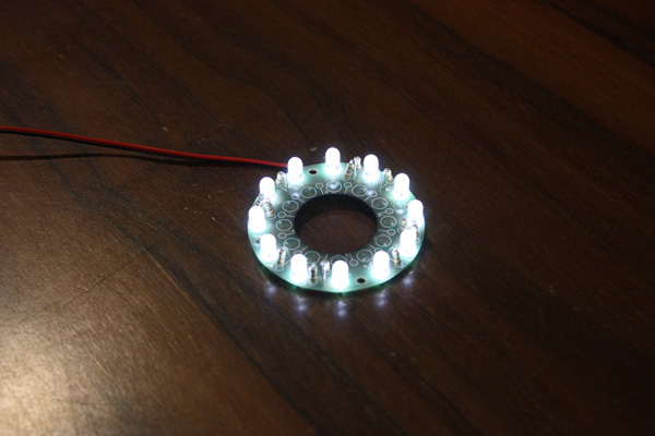
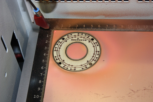
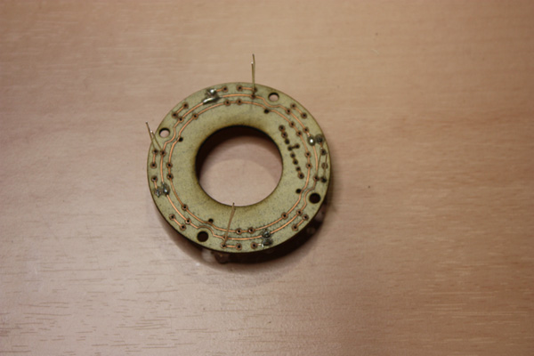
Engraved data
Make housing and hood
I designed by Rhinoceros. I made housing by 3D print
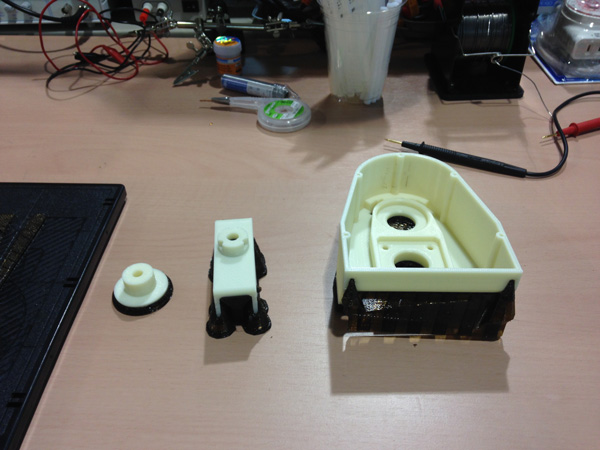
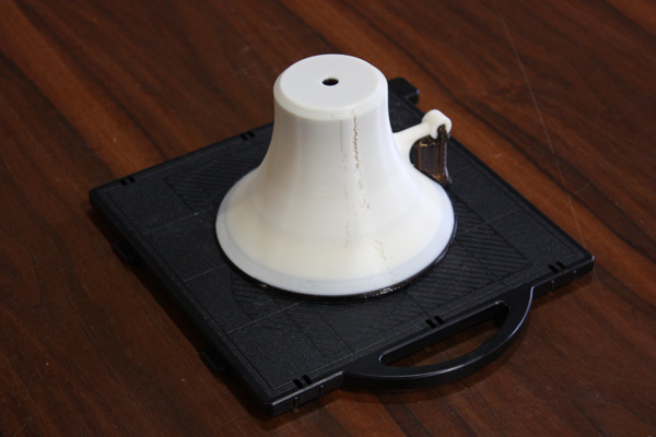
Design mechanism
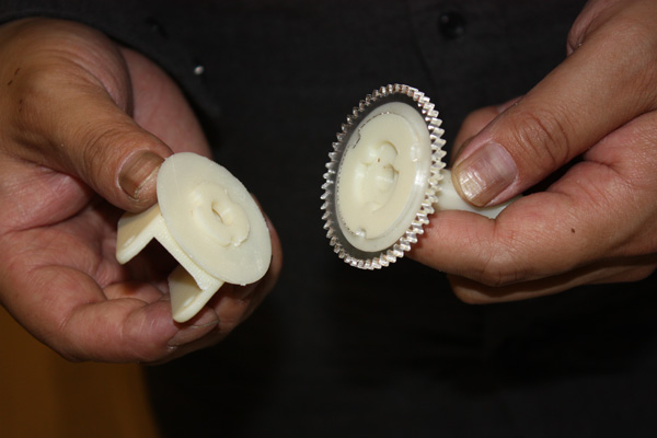
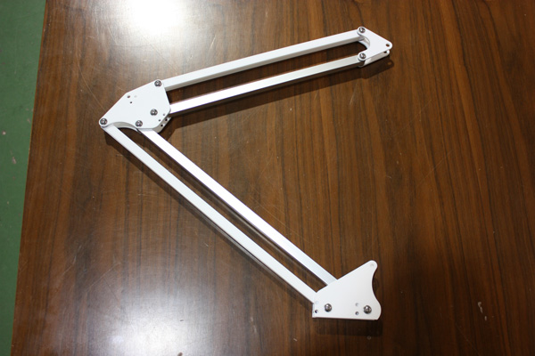
The light arm moved by gear. I assembled thrust needle bearing for smooth moving.
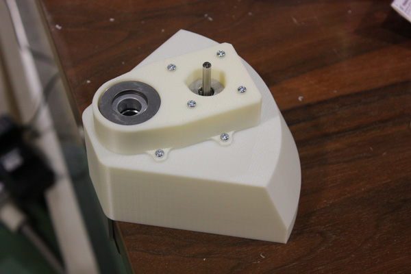
Desigh deta
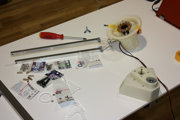
Assembly
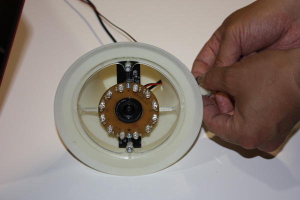
"Creative scaning / Extreme scaning"
Project proposal(Mar/2015 wrote )
I was excited to see the pulpy data generated by 3D scan system while I did week 5 assignment.
I think it is not the right decision only correctly output.
3D scanning have potential for creative field. If I know the generated scheme, I can catch invisible anything.
I intend to start the “Creative scanning.”
Results
“streaming data driven fabrication machine”
Project proposal(Jan/2015 wrote )
For my final project, I want to make a “streaming data driven fabrication machine”.
Currently, all the fabrication machines need complete modeling data. I call this type of fabrication machine as “download data driven machine.”
Instead of this type of machine, I propose the “streaming data driven machine”.
The streaming data driven machine makes an output model with getting data generated by user behavior at that time.
The streaming data driven machine can physicalize your performance.
If you sing in front of the machine, the machine reflects it on the output model.
Not only singing, but also the following performance can be accepted.
- singing
- dancing
- playing instrument
- gymnastic exercises
- cooking