- Logged in as: fablabtaipei (fablabtaipei)
- Recent changes
- Media Manager
- Sitemap
- Admin
- User page
- Update Profile
- Logout
User Tools
- Logged in as: fablabtaipei (fablabtaipei)
- Admin
- User page
- Update Profile
- Logout
Site Tools
Table of Contents
Input Devices
Input Devices
Goal
measure something: add a sensor to a microcontroller board that you've designed and read it
PCB
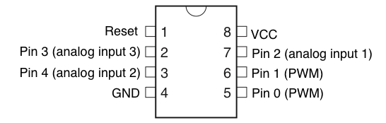
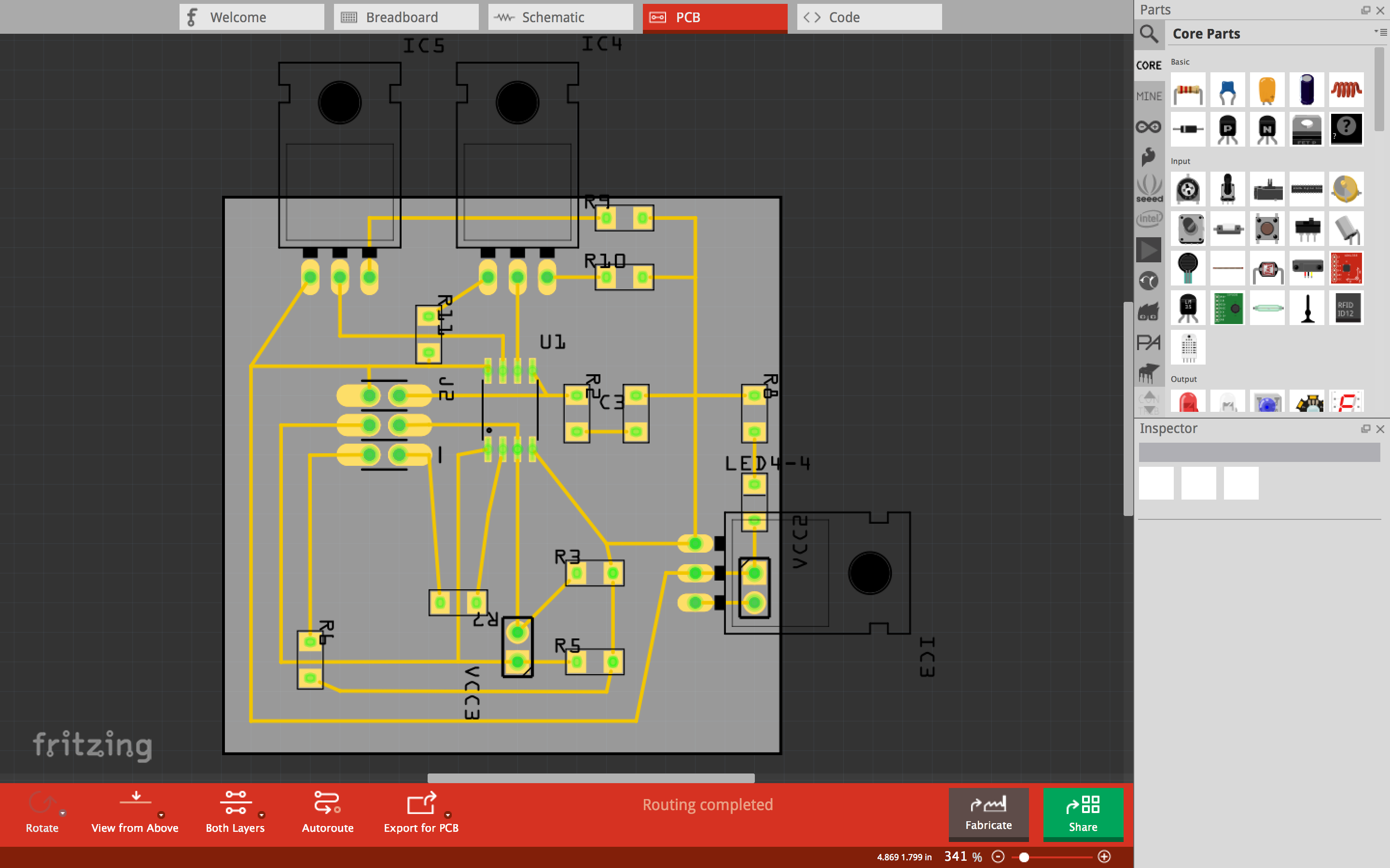
In my design there are two analog inputs and two pins for I2C. It's important to refer to the specs of Attiny 45 before drawing the layouts because pins serve certain purposes. At first I did not notice the difference of analog input and digital input and fortunately the pins I used could be used for both and only different in pin numbers ( this was another trap.) so I only had to changes in software. Some constraints are in hardware and require changes in layout. For example, pins for I2C are specifically pin 0 (SDA) and pin 2(SCL).
You may download the fritzing layout: week11_i2c_input.fzz
Sensor
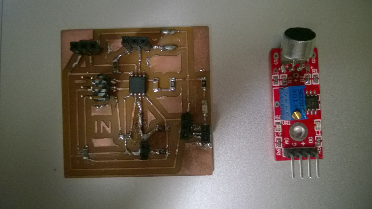 The sensor I use here is a sound sensor to detect amplitude of audio inputs. It has a pair of analog and digital output pins and I use only the analog one which is generally sufficient.
Connection
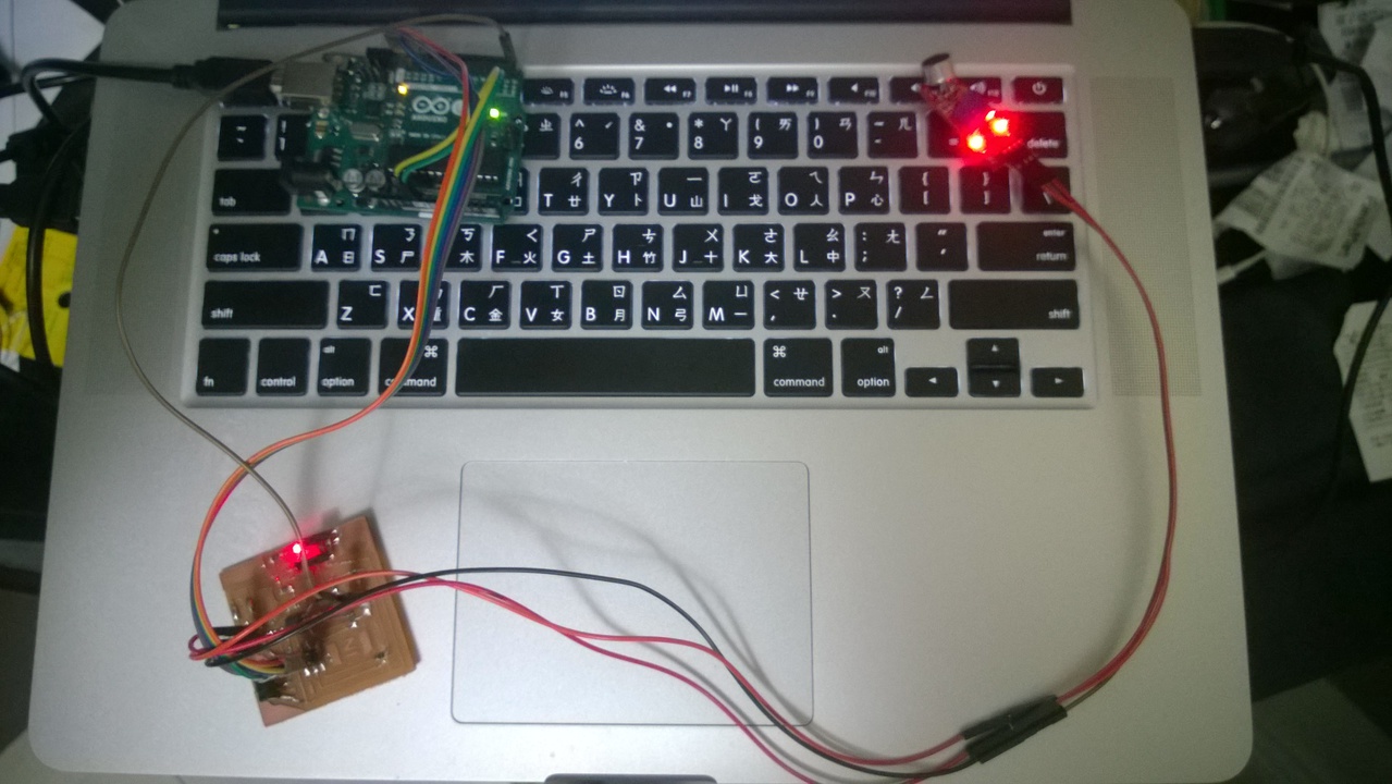
As before I use Arduino Uno as ISP, but it also serves the connection between Attiny 45 and my laptop this time. Whenever Attiny 45 receives a signal from sound sensor, it transmit a byte to Arduino via TX. Then Aruduino transmits a message in ASCII code to laptop via USB. Here are a few things to note.
There were a few different functions and optional arguments you could use in serial networking. I did not make clear how they worked and keep seeing wrongly-encoded text on my laptop. Here are some tips:
- Serial.write: send data in bytes (When sending a byte 0, it send 8 bits of 0.)
- Serial.print: send data in ASCII code (When sending a byte 0, it sends a char 0 in ASCII, which is 48 in decimal.) Optionally you can give a second argument such as DEC, HEX or BIN for representation.
- Serial.read: read in one byte.
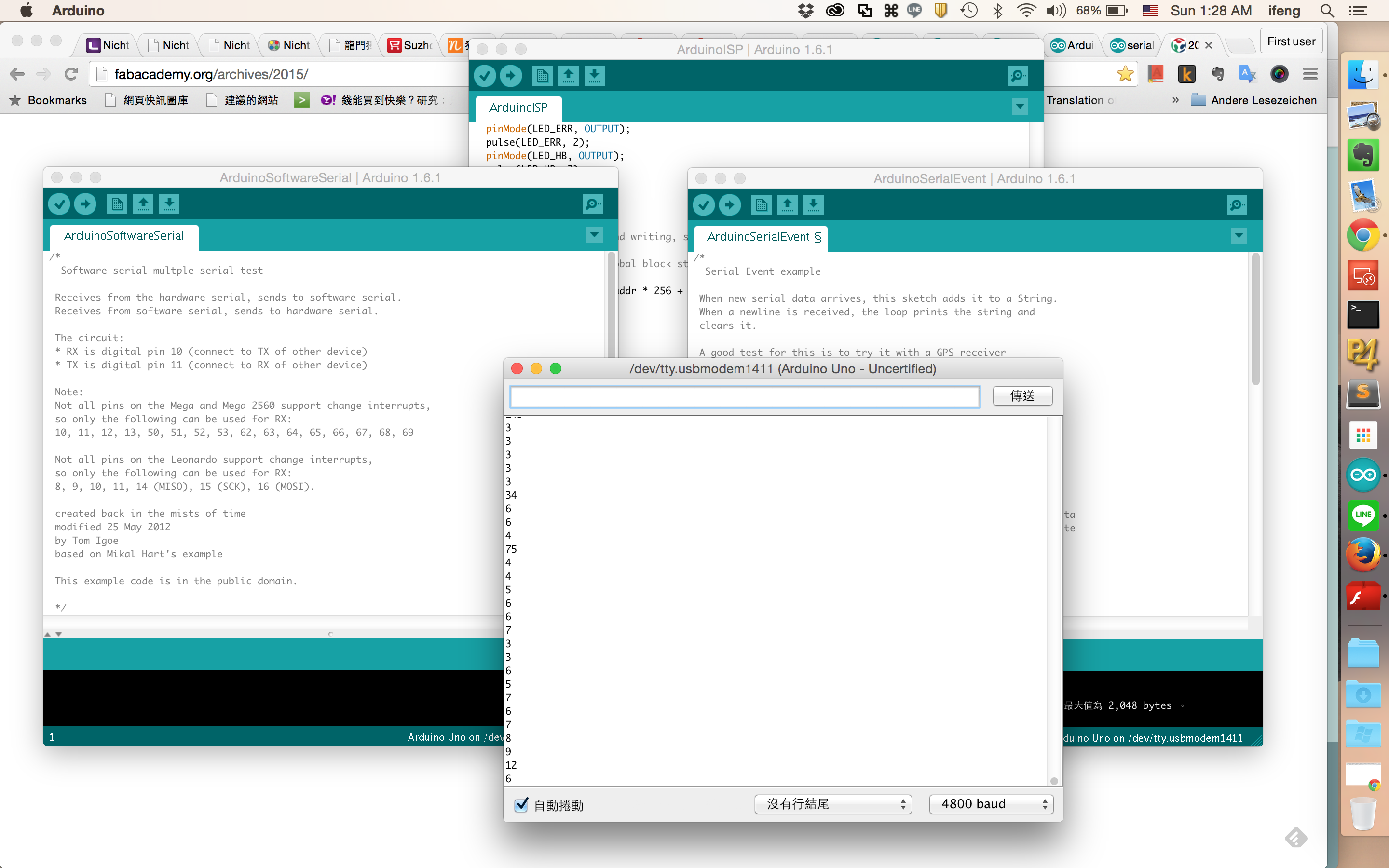
Thumb of rules: Always use Serial.write and unless the message is for humans to read. To test for connection, Arduino has a serial monitor that is very handy for debugging.
Programming
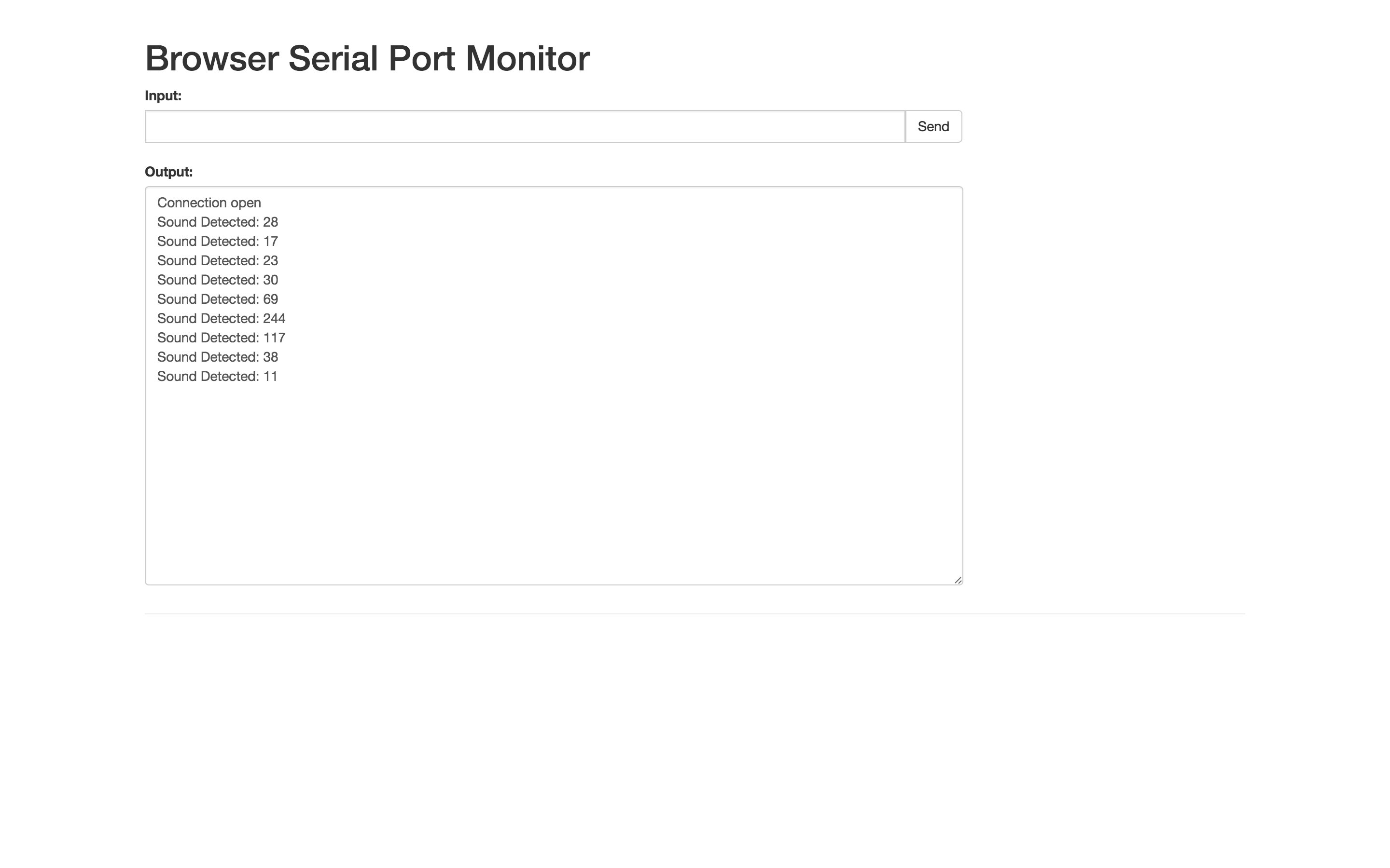
Sound sensor outputs a value ranged from 0 to 1023 which is larger than one byte. To make it simple, the output is divided by 4 to fit in one byte. In this case, the signal of “quietness” is about 8 or 9, so Attiny 45 is programmed to send out a byte only when the input is larger than 10. It has a delay of 100ms after the sent message to avoid repeating. On Arduino, it prints out what ever it receives with a human readable message. This time I use Serial Monitor in Chrome Apps to receive what the messages. It works very well.
The following code is for Attiny 45 to receive a analog input and send it via SoftwareSerial:
//SOUND Sensor
#include <SoftwareSerial.h>
SoftwareSerial mySerial(0, 2); // RX, TX
int sensorPin_A = 3;    //Microphone Sensor Pin on analog 3
int sensorValue_A = 0;
byte sensorValueA_scaled = 0;
void setup() {
  mySerial.begin(4800);
}
void loop() {
  // read the value from the sensor:
  sensorValue_A = (int)analogRead(sensorPin_A); // sensorValue_A ranges from 0 to 1023
  sensorValueA_scaled =  (byte) (sensorValue_A /4) ; // divided by 4 to fit in a byte 0 ~ 255
  if ( sensorValueA_scaled > 10 ){  //The 'silence' sensor value is about 8 or 9
      mySerial.write(sensorValueA_scaled);
      delay(100);
  }
}
The following code is a modified SerialEvent example for Arduino to print whatever it receives:
String inputString = "";         // a string to hold incoming data
boolean stringComplete = false;  // whether the string is complete
char buff[4];
byte inByte=0;
int inInt=0;
void setup() {
  // initialize serial:
  Serial.begin(4800);
  // reserve 200 bytes for the inputString:
  inputString.reserve(200);
}
void loop(){
}
void serialEvent() {
  while (Serial.available()) {
    inByte = Serial.read();
    Serial.print("Sound Detected: ");
    Serial.println(inByte, DEC);
  }
}