
Electronics Production
Make the FabISP in-circuit programmer
download (firmware, rml files)
Milling the PCB boards
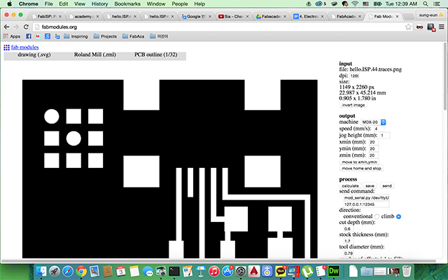
I used the Fab Module program with Linux OS at Fab Lab, and Roland SRM-20 Milling Machine.
-
Have to prepare 2 kind of files. the first one (hello.ISP.44.traces.png) is for engraving the pcb traces, and the second file (hello.ISP.44.interior.png) is for cutting Outline.
-
Using different endmills for Each files. the 1/64inch one (0.4mm) is for engraving, 1/32inch (0.8mm) is for cutting.
-
Check the setting for the milling machine. I set lower speed than usual for saving endmill. It is easy to break when it goes fast and make pressure.
setting for cutting (1/32’’) : speed=0.5mm/s, cut depth = 0.6mm, thickness = 1.7mm
setting for engraving (1/64’’) : speen=3mm/s, cut depth = 0.1mm, offset overlap = 50% -
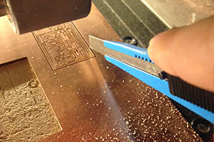
Changing the mill, settle the board with double-sided tapes. When zeroing, have to careful for not braking the mill, and touching exact surface.
 |
 |
 |
 |
Failures
-
It didn’t engraved entirely because of the bad zeroing. It doesn’t touching exact surface. when I pushed down surface little bit, I can cut deeper.
Soldering the components
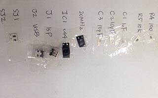
prepare and understand each components, solder it.
-
setting up the components. Wrote the part names and fix the components with adhesive tape. It was useful because the components are very small so I can easily lose them.
-
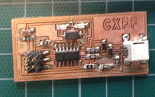
soldering. Flux was very helpful to soldering.
-
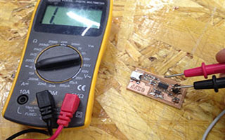
Testing. First, visual inspection of the board. make sure every solder joints is shinning. Second, check all the connections using multimeter.
 |
 |
 |
 |
Failures
-
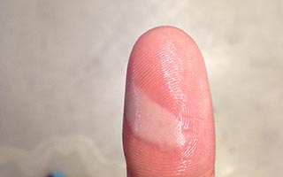
I got burned by soldering iron.. I was being careless. I just grabbed it. there are some safety warnings of soldering
-Take care of your soldering tool.
-Do not work on electrically live parts.
-Remove the power plug from the socket before opening the unit.
-Use a soldering vapor suction device. I soldered Diodes wrong way. I should have to check the Diode's polarities. Diodes only allow current to flow in one direction, and they are always polarized. The positive side is called the anode, and the negative one is called the cathode. Usually the diode will have a line near the cathode pin, which matches the vertical line in the diode circuit symbol. When I changed the polarities, then It works.
Don't forget to power to the both boards; programmed one and being programed one.
Programming
I followed the tutorial link below
http://fabacademy.org/archives/2015/doc/programming_FabISP.html
-
install avrdude / GCC software
-
Power the FabISP board
I programmed this board with my instructor’s FabISP board. first time I failed because I didn’t power the both two boards. -
Edit the Makefile
I programmed with another FabISP so I changed the lines like below.
AVRDUDE = avrdude -c usbtiny -p $(DEVICE) # edit this line for your programmer
#AVRDUDE = avrdude -c avrisp2 -P usb -p $(DEVICE) # edit this line for your programmer -
Program it (terminal)
go to firmware folder -> make clean -> make hex -> make fuse -> make program
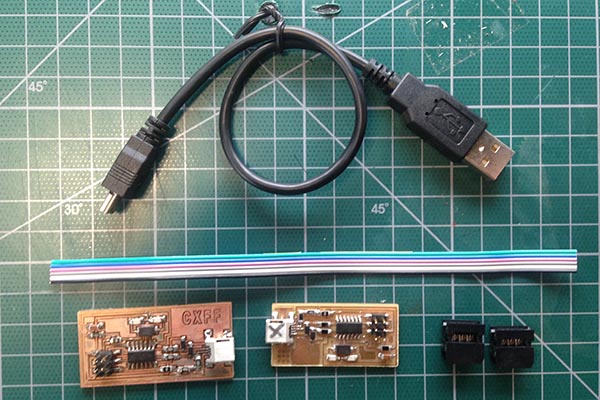
Needed parts for programming : a USB to mini-USB cable, a working FabISP board (pre-programmed), FabISP board what I'm going to program it, two 6pin connectors, and cable.
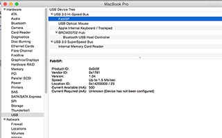
When it was programmed well, I can find the USB device named "FabISP" in System reports in MAC OSX.
About this MAC -> System report -> Hardware -> USB -> USB Hi-Speed Bus -> FabISP