
BRITOV DENIS
FINAL PROJECT NEW EDITION
What will it do?
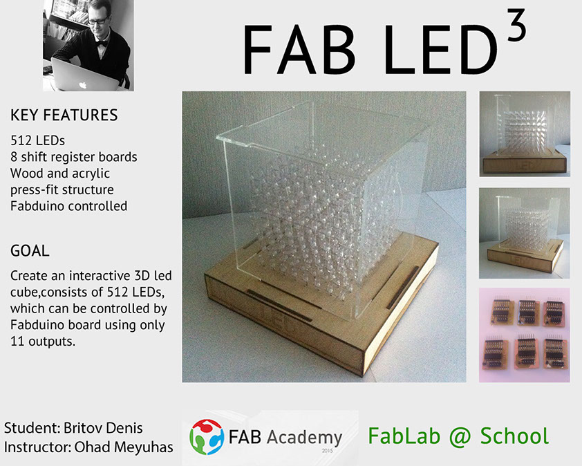
My final project will be a 3D 8x8x8 LED cube controlled by fabduino board.
Consist of 512 LEDs, it can display some kind of 3D signs.
What materials and components will be required?
- 512x LEDs
- 64x 100 Ohm resistors
- 8x 74HC595N ICs
- 8x transistors
- Fabduino board
- Acrylic
- Plywood
Step 1: Soldering a LED cube
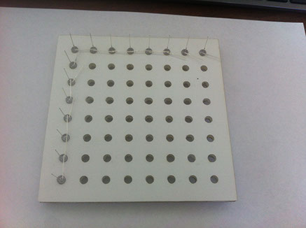
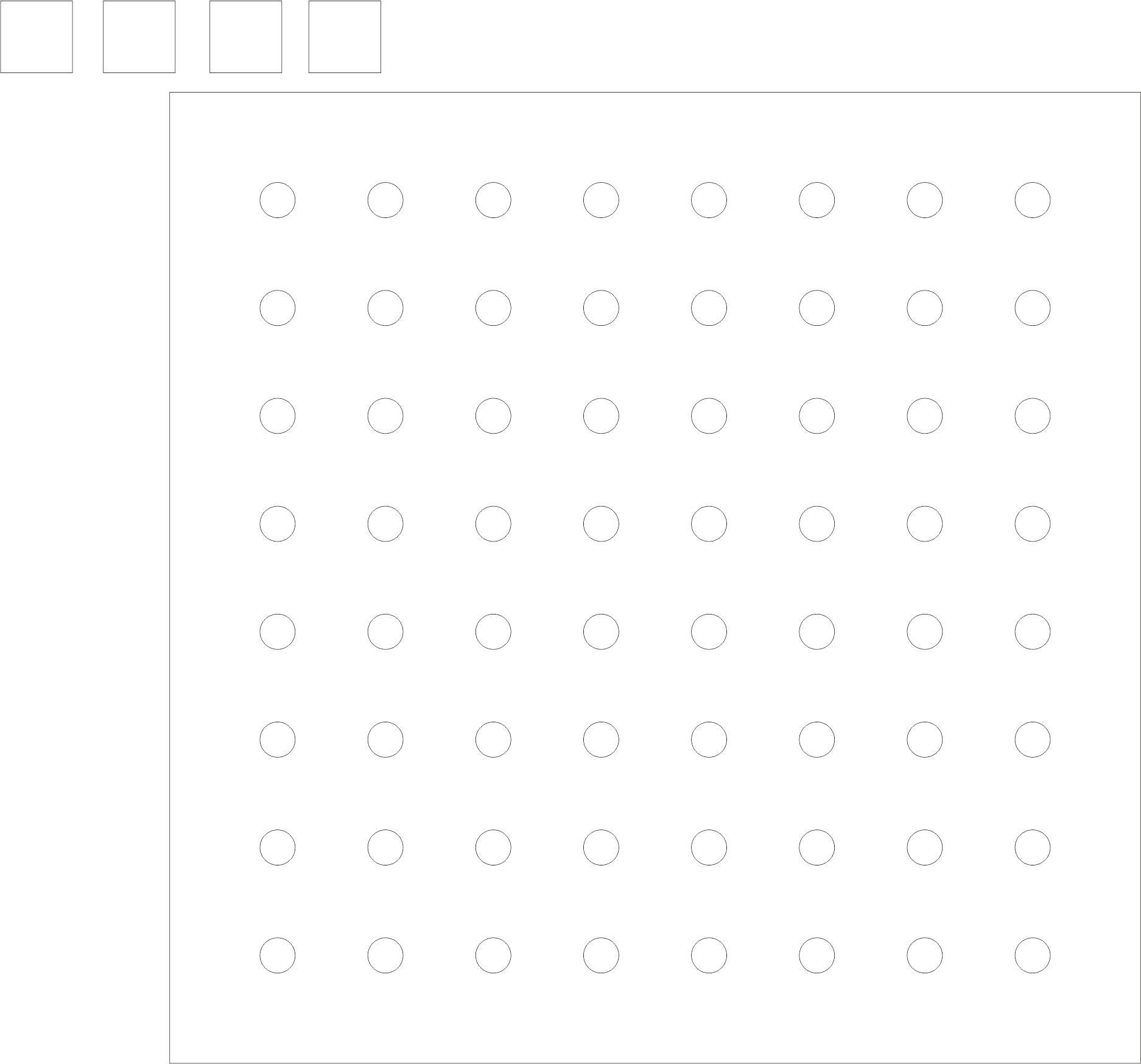
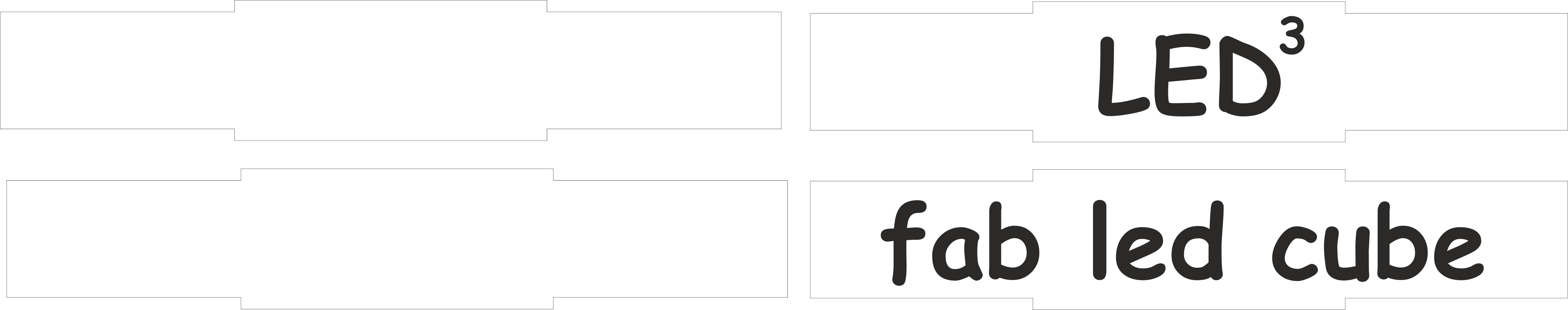
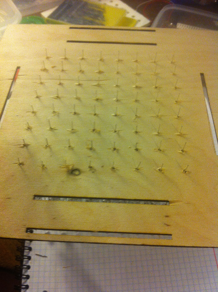
It`s huge, boring but very important part of this project. To simplify the production,
i cutted a template for the LED matrix. It looks like:
You can download template HERE.
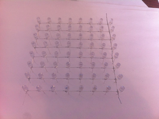
This template helps to solder one LED to other. As you can see on the photo firstly you should bend cathode of each (them 512) LED to 90 angle. Then:
- Sorder one horisontal row
- Solder 8 vertical rows
- Check LED matrix, some of LEDs may be demaged, and it`s the best time to replace it.
- As you can see the construction is very fragile, so solder wire at the bottom side
The result shoul looks like:
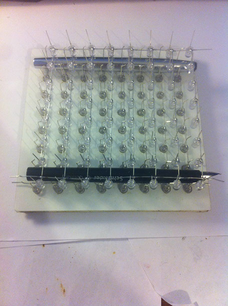
Good, now you should bend each anode like this. It help to connect one layer to another one.
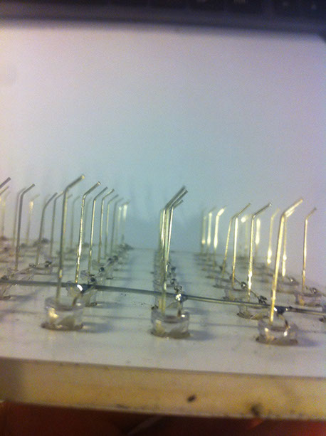
Next step is soldering layers to each other. It`s very difficult process, so be carefull.Use something to devide layers. I used simple pen.
So, you have a cube. Let`s create an electronics.
Step 2: Electronics production
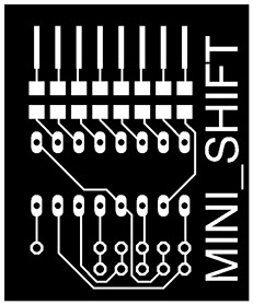
Now we should create the board, that can controll all 512 LEDs. It was not possible to produse one big board, so i create a universal little board, number of such boards can be connected togather. Each board have 8 outputs, so we need 8 boards to controll 8*8=64 anodes. Another one board needed to controll 8 cathodes, which controlles the layers of our cube.
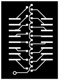
Mini Shift board:
Components:
- Shift registor 74HC595N
- Resistors 100 Ohm x 8
- Headers

Output board:
Components:
- 8 n-chenell transistors
- Headers

Here is eagle files for this boards: led.zip
The result after soldering looks like:
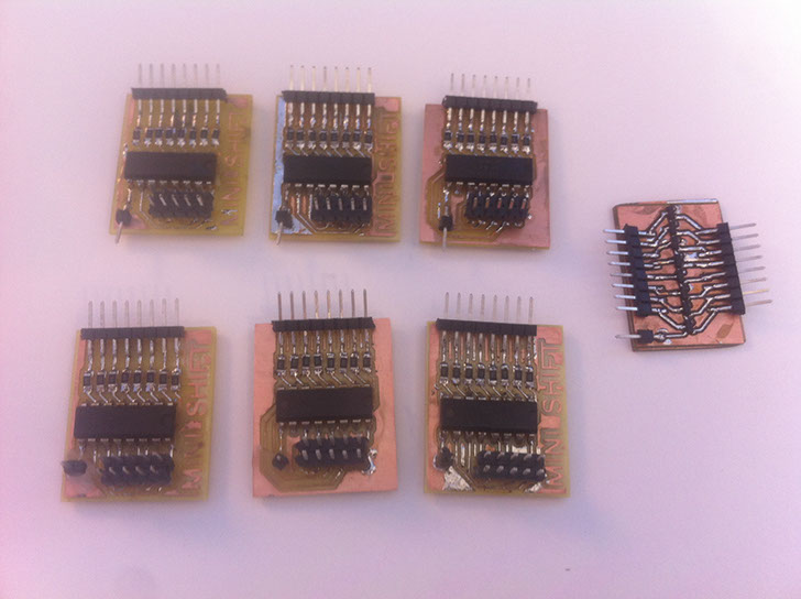
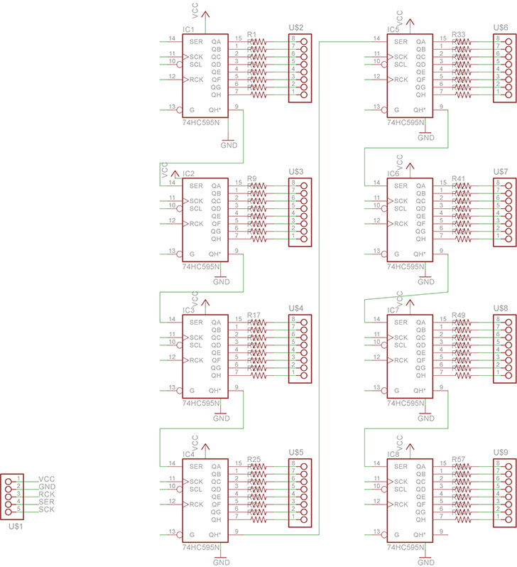
To understand how them should be connected use this picture, i created to my big bourd:
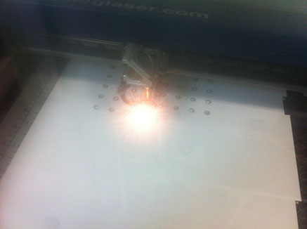
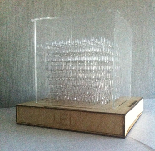
Step 3: Case building
The case consist of 2 parts: bottom - there will be all electronisc, i cut it from plywood.
top - transparent part to protect LED cube
I cut all parts using Laser cutter, so here is files to do this: Top Bottom Fronts Box
Step 4: Final assembly
First - take top part of bottom box and insert all LED wires into the holes.
Bend them and solder the wires to connect the LED rows to the Shift boards. Solder 8 wires - one to each layer - they will be connected to OUT board.
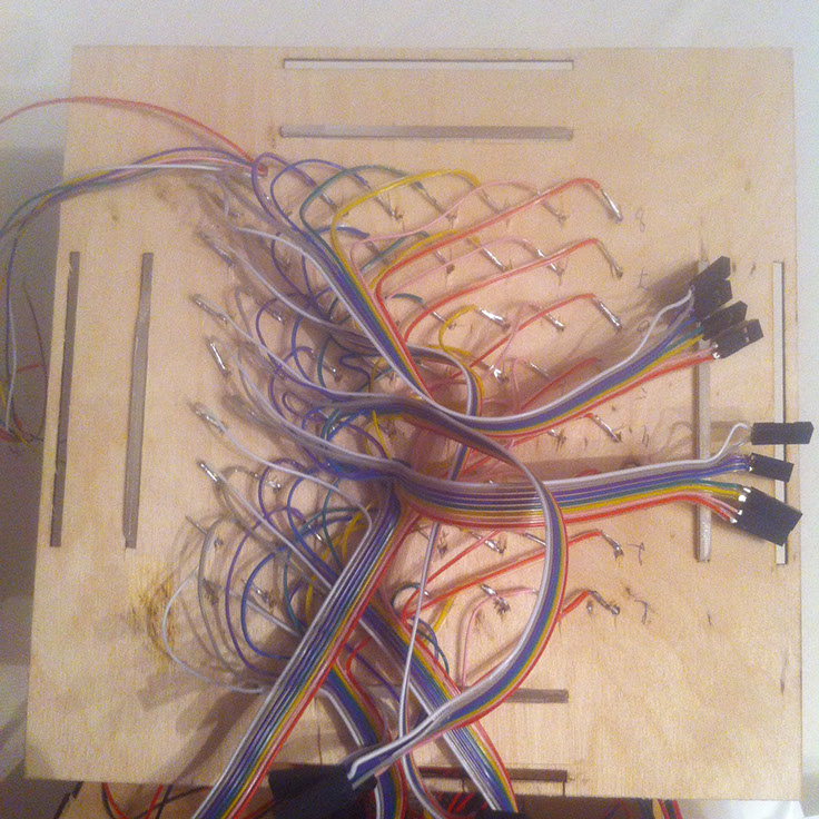
Connect all boards to each other, connect fabduino to the first Shift board and connect LED cube to the boards.
Assemble all other parts. I fix my boards in the bottom box with double side tape.
It`s ready!
Step 5: Programing
Here is a test program to control LED cube:
int latchPin = 8;
int clockPin = 12;
int dataPin = 11;
void setup() {
pinMode(latchPin, OUTPUT);
pinMode(clockPin, OUTPUT);
pinMode(dataPin, OUTPUT);
}
void loop() {
for (int numberToDisplay = 0; numberToDisplay < 256; numberToDisplay++) {
digitalWrite(latchPin, LOW);
shiftOut(dataPin, clockPin, MSBFIRST, numberToDisplay);
shiftOut(dataPin, clockPin, MSBFIRST, 255-numberToDisplay);
digitalWrite(latchPin, HIGH);
delay(500);
}
}
Second part - to control activity of each layer. This program activate each layer till 1 second.
#define SSpin 8
#define SCLKpin 12
#define DATApin 11
#define L1 22
#define L2 23
#define L3 24
#define L4 25
#define L5 26
#define L6 27
#define L7 28
#define L8 29
void setup()
{
pinMode(SSpin, OUTPUT);
pinMode(DATApin, OUTPUT);
pinMode(SCLKpin, OUTPUT);
pinMode(L1, OUTPUT);
pinMode(L2, OUTPUT);
pinMode(L3, OUTPUT);
pinMode(L4, OUTPUT);
pinMode(L5, OUTPUT);
pinMode(L6, OUTPUT);
pinMode(L7, OUTPUT);
pinMode(L8, OUTPUT);
// Serial.begin(9600);
// Serial.println("reset");
}
void loop()
{
for (int i = 22; i < 30; i++)
{
digitalWrite(i, HIGH);
for(char thisLed = 1; thisLed < 64; thisLed++)
{
registerWrite(thisLed, 1);
registerWrite(thisLed-1, 0);
delay(70);
}
digitalWrite(i, LOW);
}
}
void registerWrite(byte whichPin, bool whichState)
{
static uint64_t bitsToSend = 0;
if(whichState) bitsToSend |= 1LL<<whichPin;
else bitsToSend &= ~(1LL<<whichPin);
digitalWrite(SSpin, LOW);
for(byte i = 0; i < 64; i++) // "проталкиваем" байты в регистры
{
digitalWrite(SCLKpin, 0);
if((1LL<<i)&bitsToSend) digitalWrite(DATApin, 1);
else digitalWrite(DATApin, 0);
digitalWrite(SCLKpin, 1);
}
digitalWrite(SSpin, HIGH);
}
Play with it and you achieve your goal =)
Video: