Our assignment for this week was to make something big using the shopbot-machine and to improve the understanding of this items:
There are two main things I wanted to try with big CNC router:
Make a 2D cutting:
I always wanted to try customising my surrouding or to make something extraordinary. That's why my firs step in this direction is to make a document-shelf(it will be the most documented one, with some theory) and the second is to make a goban!
Make a 3D cutting:
Playing with new technologies is interesting, but it is sometimes better to walk the safe way and use some tutorials instead of experimenting. So for the first I decided to try the example from artcam tutorial I found in our lab and make the cell-phone panel. But all that glitters is not gold and I had a lot problems with implementing this thing.
The second thing here was to make the mold for composite materials!
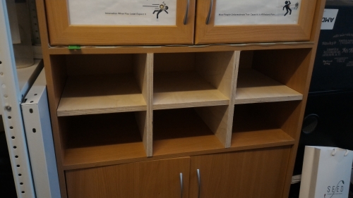
First, I made a shelf for documents that can be easily inserted into the bookcase to provide you with separator. That makes sence when you need, for example, to separate your paperwork flow into some thematic subflows:
The good thing in doing something is to understand how does it all work, so...
The big CNC-machine is the executive subsystem of CAD-CAM system. That means that the fabrication is made through this steps:
Please note well, that it appeared so, that I had to use localised software this time and I don't know how exactly are the menu items called in english, so I use my own translation. To be sure you understand it all correct please take a look at the pictures.
I draw the shelf details in CorelDraw because that was the easiest way at the moment
First thing was to draw the primitives to form the outline from them. I prefer using rectangles and make binary manipulations on them or turn them into lines and play with vertices. Also when it is sometimes helping a lot do draw some projections of the thing you are trying to design. Here is the frontal view of my shelve with details that form it
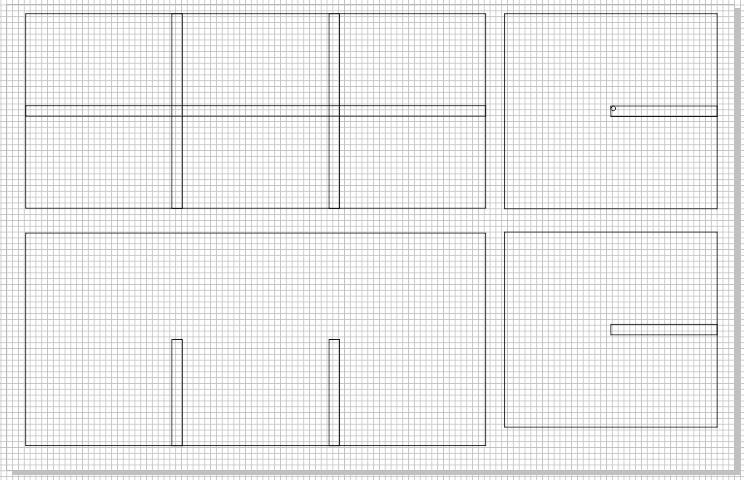
There is a trick in cutting the shelves like this called dog-bone-fillet (there is also t-bone-fillet, and they both are the ways to make the detail with the inner corner to be able to contact with another detail. There is really nice explanation of this thing and some others here). For my case to get some additional experience I decided to make some details with dog-bone fillets and to rasp the others:

|

|
Here are the coreldraw file with all the details and dxf export files for horisontal and vertical details.
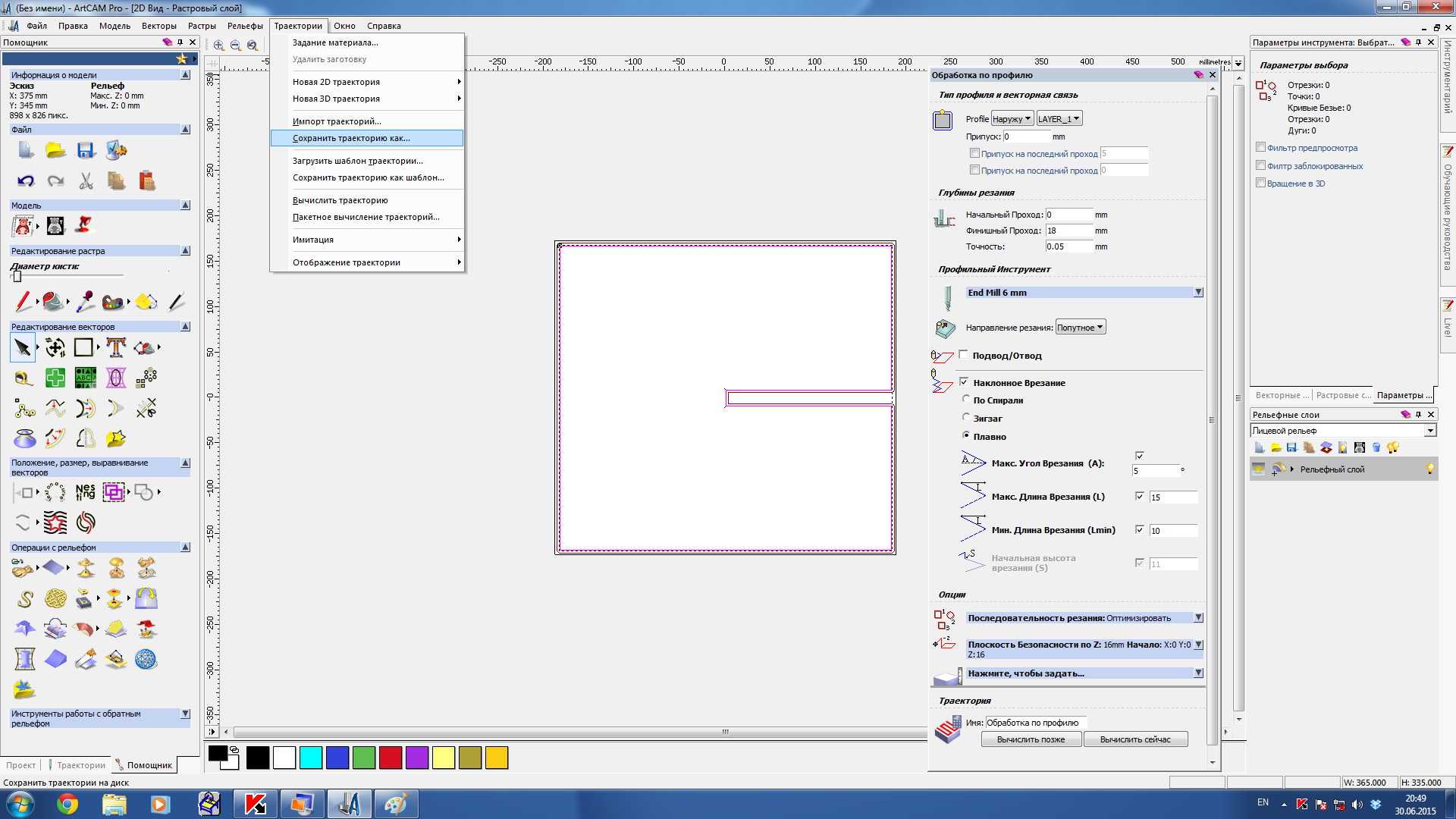
After you imported the vector image you need to choose 2D trajectory -> contour:
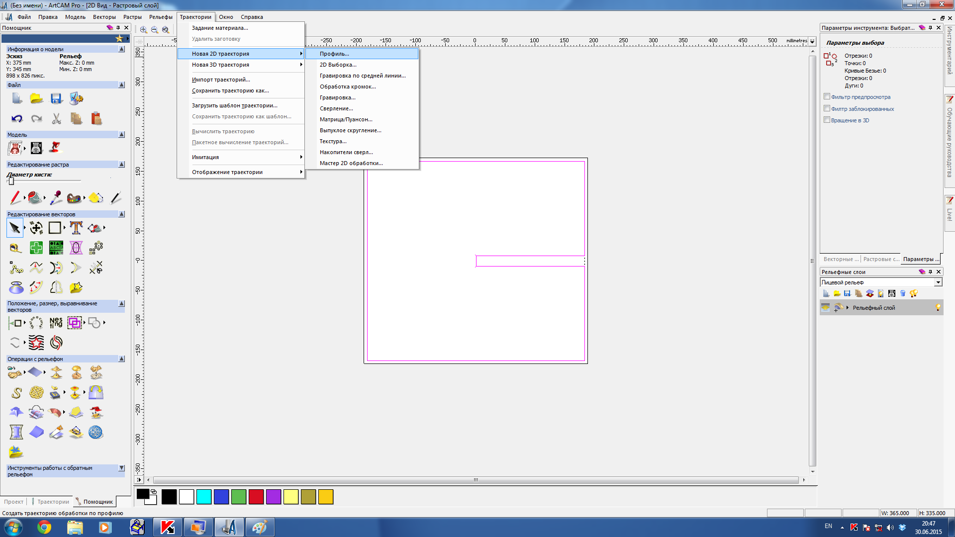
After you choose this item, you can see the menu shown on the picture below. It contain tool specifications, some rules of making the toolpath and some information about the material we are using:
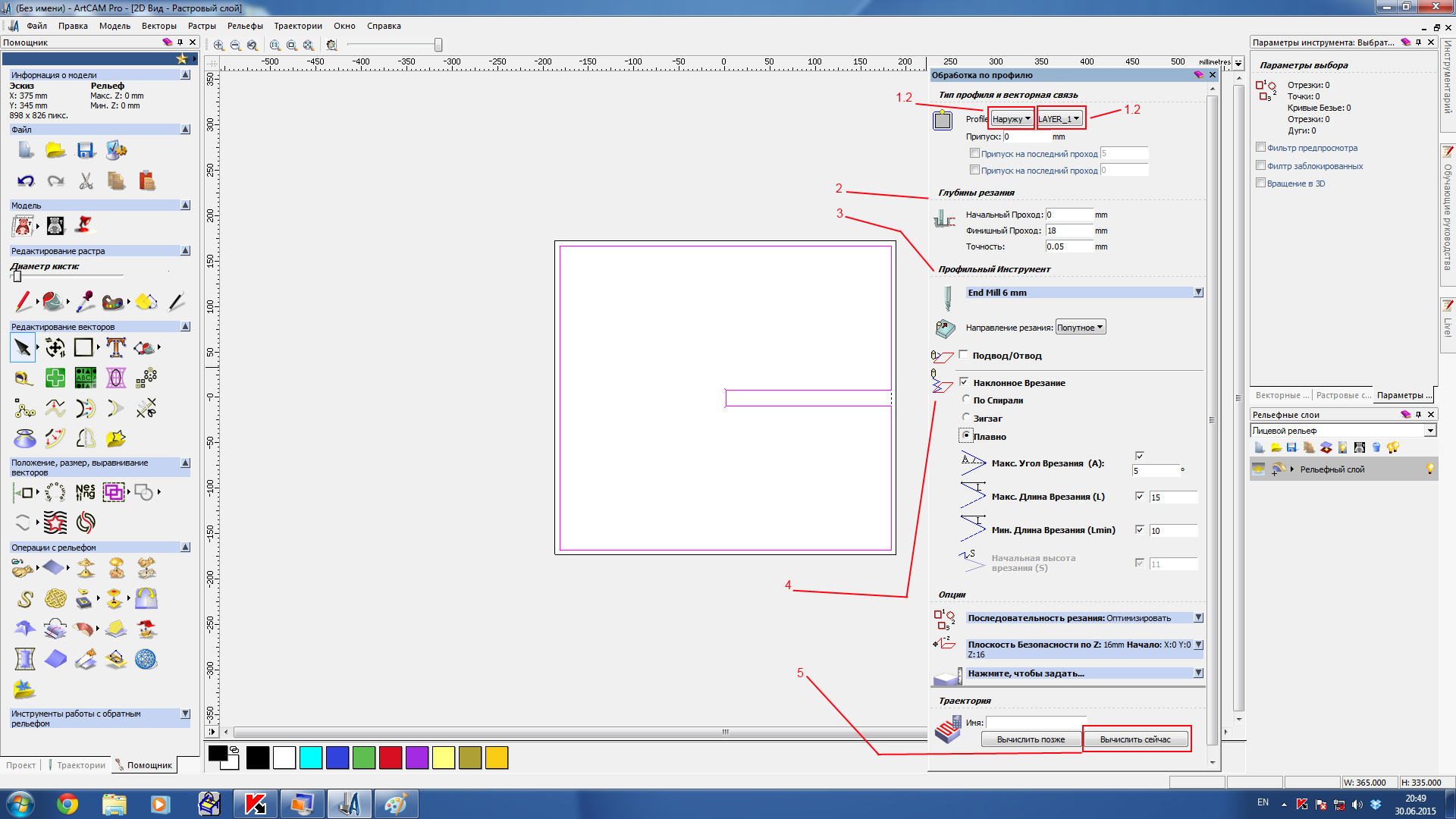
some explanations:
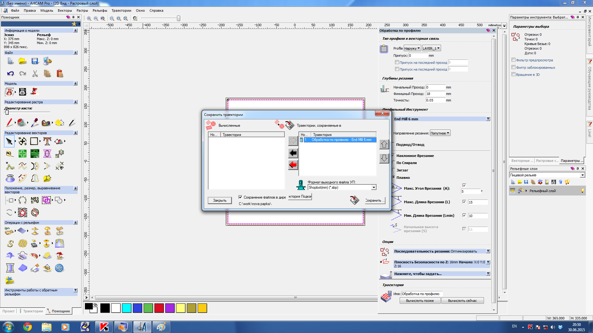
After that you need to choose from the upper menu: "trajectories" -> "save trajectory as".
|
|
|
At this point we're done with Artcam, because we have the sbp-file that can be interpreted with shopbot-software
Here are the spb-files for the shelve: horisontal detail, dog-bone-fillet for horisontal detail, vertical details, dog-bone fillet for them.
What are those files we have from the Artcam? The Shopbot *.spb files wre the trajectories generated from our blueprints.
How are they described in the way the machine can understand them? There is a special scripting language for CNC machines called G-code. It gives us an opportunity to tell the machine where to move, how fast to move and through what path to move. You may find more interesting information about G-code commands here
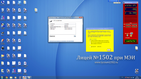
Shopbot is a G-code translation software that can send the G-code to your machine's controller and make it either run g-code from the *.spb file or run simple commands, one at a time, like move along any axis. It also allows to controll movements manually.
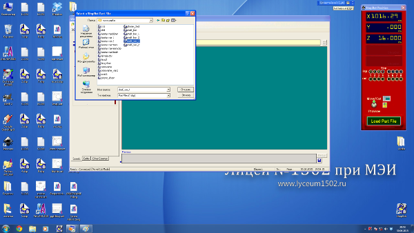
We have shopbot installed on computer running windows7 and the version we have requires xp-mode. Thus we need to allow the software from xpmode to access the real ports:
|
|
|
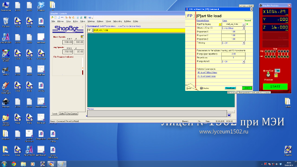
That's how the shopbot-window looks like:
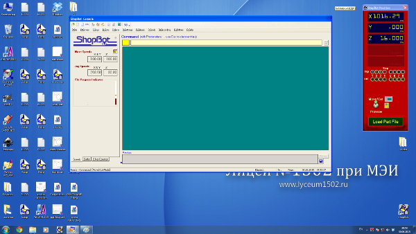
We need to load the path-file:
And after that (if everything is correct) we can start the machining:
I found the useful page about how to work with shopbot (it is like a checklist of everything you need to do). And also you may find all the information needed to start using CNC router at this fablab wiki
Goban is a board for playing the Go. I wanted to learn playing this game because it develops strategical thinking and made a huge impact in modern tecnology culture (for example Atari philosophy was inspired by this game spirit).
That how can really beautiful goban look like:
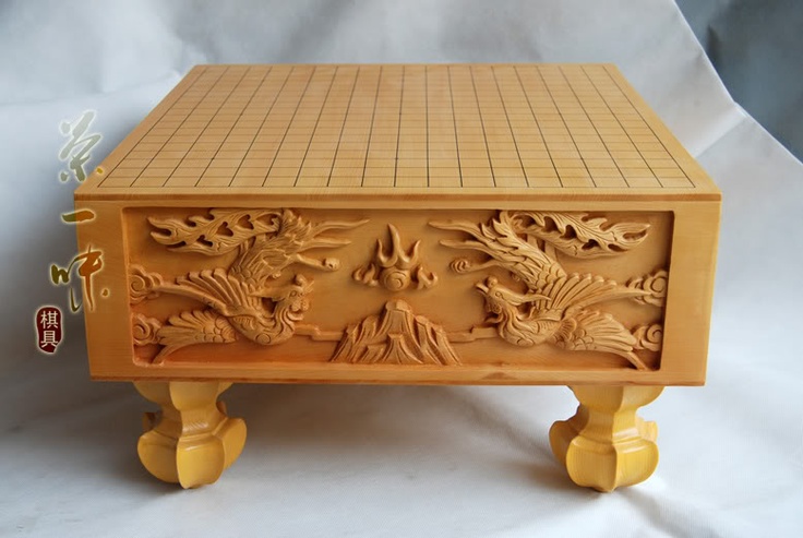
Traditionally goban is made from solid piece of wood, but there are cheap versions that are even made from cardboard (just the upper surface, not the whole board. My will be something in between those options. I am about to make the wooden box from softwood and enrave the grid with laser on it. Maybe later I will try to make 3D-ornaments just like on the goban above. Let's do that!
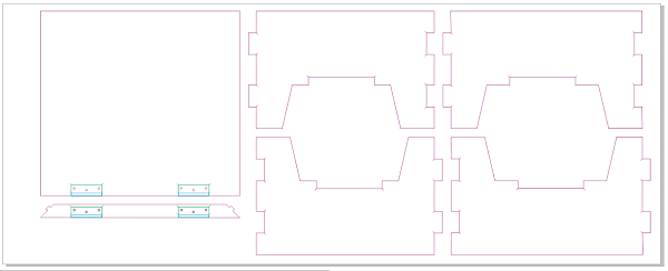
Here are the details I need to do to assemble the goban:
 I decided to make it with the hinges, like a chest so I could keep the stones in it.
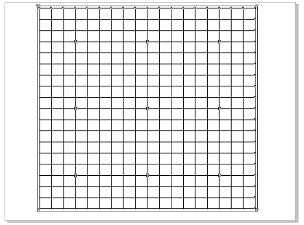
As far as the wooden sheets I wanted to cut everything from are 1500mm x 600mm, I need to limit the size of working space by this values. It gives me this:
|

|
I also need to engrave the grid on the top to be able to play:
Our shopbot machine is a little unstable and it has been being repaired recently. But I hope I can finish my goban as soon as it's possible - can't wat to try it!
Here are all the files coreldraw files: all details, first sheet, second sheet and the grid.
making such a cell-phone panel was an example from the artcam handbook we had in our lab. So I decided to start my 3d-experiments from that point
When I was testing the big milling machine for the first time it began to behave in a strange way! I was trying to make a mold for a simple 2.5D cell-phone model. Everything was fine but then suddenly machine shifted all the model to the right for 10mm or something like that. There were also some clicking sounds sometimes when it moved.
That's how the result looks like:
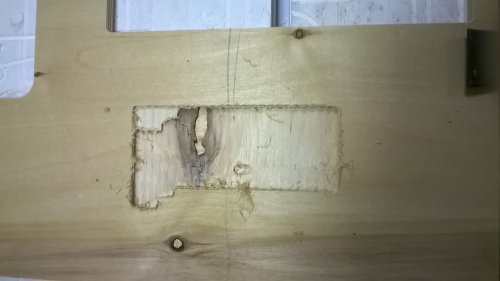
I tried to investigate this case, but found nothing suspicious: g-code was looking nice and previews in artcam were looking nice too. That's strange.
Later I noticed that if machine stucks in some point and the engines still run (mechanics is slipping) the router's controller "think" that the movement has really been done and increments the coordinates. This, it seems that at one moment the tool was unable to cut the plywoon, the whole machine stuck, the mechanics slipped and despite the movement hasn't been done in fact, tools coordinate was incremented. It caused the shift for the next frame and cutting the material there was even harder, so the problem worsened.
After I faced this problems I didn't try to make this panel from plywood anymore. Though now I can see some tricks that could help me avoidint this problem
The last thing I wanted to try was making the mold for composite material (see my composites).