Measure something: add a sensor to a microcontroller board that you've designed and read it.
How to read sensor data?
Connection
One contact of the sensor (usually red) you should connect to the voltage (read in datasheet: to 3.3V or to 5V), another contact (usually blach) you should connect to the ground and the third contact - to the controller (to digital or analog pin - depends what data you want to obtain). Sometimes sensor have more than 3 contacts, so read datasheet for them carefully. Might be useful:
+, VCC - positive voltage;
-, G, GND - negative voltage;
DO - digital output;
AO - digital input;
S - signal cabel.
Usage
Information from sensor usually represented as level of voltage (0V or 3.3/5V as false and true in digital case, and 0 to 3.3/5V as numbers from 0 to 1023 in analogue case). If you connected sensor to analog read pin - do not forget to map numbers from 0 to 1023 to sensor value (formulae usually can be found in Internet/datasheet for the sensor).
Example for audio sensor
AO - analogue output signal, DO - digital output signal, GND - ground, "+" - voltage.
Put sensor to breadboard so its pins will be connected with different lines (breadboard lines. Connect cables and Arduino (G - GND, "+" - 5V, AO - A0, DO not in use):
We can read signals from Arduino using analogRead(A0), than we can understand what's going on using serial monitor:
const int analogInPin = A0; // Analog input pin that the potentiometer is attached to
int sensorValue = 0; // value read from the pot
int outputValue = 0; // value output to the PWM (analog out)
void setup() {
// initialize serial communications at 9600 bps:
Serial.begin(9600);
}
void loop() {
// read the analog in value:
sensorValue = analogRead(analogInPin);
// wait 2 milliseconds before the next loop
// for the analog-to-digital converter to settle
// after the last reading:
delay(2);
}
This code shows to Serial monitor the results of reading the code.
The biggest challenge is to make it first time and understand, how connections work. Also it's not obvious what output signal use (analog or digital) - it depends of the needs of the project.
Circuit with input
Example above were made using breadboard. Task is to design own board so I did it with Eagle.
Further text were taken from electronics page:
I decided to make my homework corresponds to the final project (smart wardrobe). I chose Intel Galileo as the base platform for the electronic part because it can be easily connected to the Internet through Ethernet network. On Galileo platform microcontroller (processor) soldered to the circuit so I decided to make a great shield with connection to RFID sensor and engine (which will open and close wardrobe).
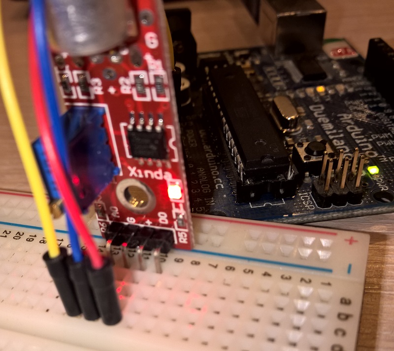
To test all things together I used breadboard:
I downloaded Eagle files of proto shield for Arduino from the official site and redesigned it. Firstly I deleted all unuseful things (to delete several items in the same time - define a group, choose delete tool and press Ctrl+Right Click on the group). I saved pins near the edges of the circuit board - the needed to insert shield to Galileo.
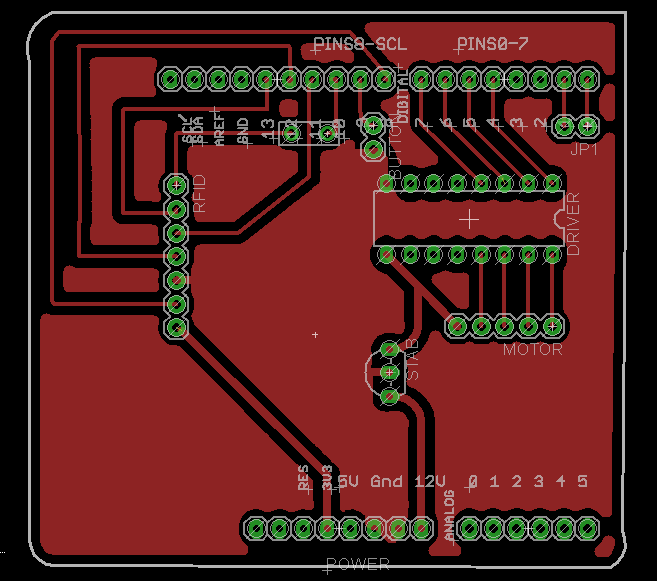
For input I used RC522 RFID sensor and some help from this page. The hint is to connect pins correctly to the microcontroller SPI interface. Final board design looks like this:
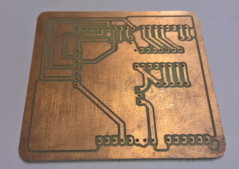
Before cutting I checked designing rules in Eagle and found that my 0 Ohm resistor is too small so I decided to use wire to connect to electric routes. Board were cutted on FlexiCAM S2 150250:
After the soldering I tested almost every connection with tester and it saved me several hours later to debug my project. How it works:
I reserved pins 0 and 1 for connection with other controllers. I used Arduino Leonardo 10 and 11 pins to connect and send commands to Galileo RX/TX pins: 1 - open wardrobe, 0 - close wardrobe. It's another way of organizing input for the board.
Если у Вашего сенсора всего три контактных провода, то скорее всего они соответствуют +, - и сигналу. Для начала Вы должны найти информацию по данному сенсору и понять от какого напряжения он работает (скорее всего 5В, но могут быть и другие варианты).
Подключение
Один контакт (как правило красный) Вы должны подключить к положительному питанию, второй контакт (как правило черный) - к земле (GND), третий контакт - к входу контроллера (A0-A.., если на Arduino). В некоторых случаях сенсоры обладают 4мя и более контактами - тогда надо внимательно прочитать подписи к контактам и документацию сенсора.
Известные сокращения:
+, VCC - положительное напряжение;
-, G, GND - земля;
DO - цифровой выход;
AO - аналоговый выход;
S - сигнальный выход.
Использование
Информация с сенсора как правило представляет из себя скачки уровня напряжения от 0 до напряжения питания (выше шла речь, что как правило это 5В, но может отличаться от контроллера к контроллеру). Для контроллеров на базе Arduino при считывании сигнала с аналогового входа выдается результат от 0 до 1023. Этот результат надо преобразовать в диапазон значений контроллера - информация об этом представлена к документации к контроллеру.
Пример на базе датчика звука
На указанном датчике AO - аналоговой сигнальный канал, DO - аналоговой сигнальный канал, GND - земля, "+" - питание.
Втыкаем датчик в макетную плату так, чтобы ножки датчика встали в различные линии макетной платы (т.е. чтобы датчик был расположен вдоль макетной платы, если таких обозначений линий нет). Пояснения по тому, как соединены разъемы макетной папки смотрите тут. Соединяем провода макетной платы и Arduino (G - GND, "+" - 5V, AO - A0, DO можно не трогать):
Считывать показания с помощью Arduino можно кодом analogRead(A0), где внутри скобок стоит номер порта к которому мы подлючили аналоговый сигнальный канал. Далее с помощью следующего кода можно вывести показания на экран:
const int analogInPin = A0; // Analog input pin that the potentiometer is attached to
int sensorValue = 0; // value read from the pot
int outputValue = 0; // value output to the PWM (analog out)
void setup() {
// initialize serial communications at 9600 bps:
Serial.begin(9600);
}
void loop() {
// read the analog in value:
sensorValue = analogRead(analogInPin);
// wait 2 milliseconds before the next loop
// for the analog-to-digital converter to settle
// after the last reading:
delay(2);
}
Представленный код выводит в монитор сериал-порта показания датчика. Находясь в Arduino IDE нажмите Ctrl+Alt+M, чтобы посмотреть его.
All electronics in one page: design, making input and output + network...