| Index About Me |
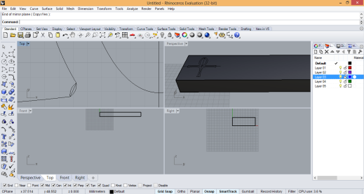
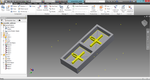
Molding and Casting AssignmentThis assignment was more challenging and difficult than it was supposed to, and many useful things were learnt along the way.The assignment was about making a mold and casting on it, so it seemed to be a clear workflow to follow, Thus, I made a Diagram in order to clarify the steps: what would have to be done, and which questions should be addressed and answered properly in order to move to the next phase: 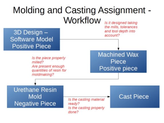 The first stage of the process was the design, and it was the most-time consuming, after wandering about several tools, I settled for two known workhorses: Rhino (for first approaches) and Inventor: 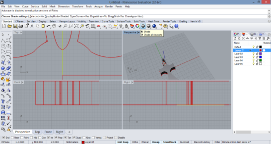 After some initial
work, I got to make and ankh
model for casting, extruding from a 2D sketch and adding a piece for
introducing a small chain, maybe a bit too small. 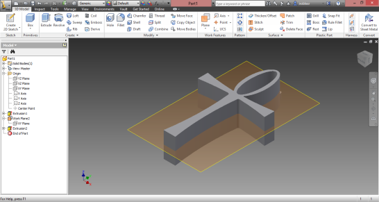 At this point, The
doubt became too
time consuming, as I was not entirely sure about the machining process,
so I worked on several designs, including manking the negative directly
and, finally, dividing the original figure in two pieces in order to
make a two section mold, I used Inventor for this, two days spent in
the process.
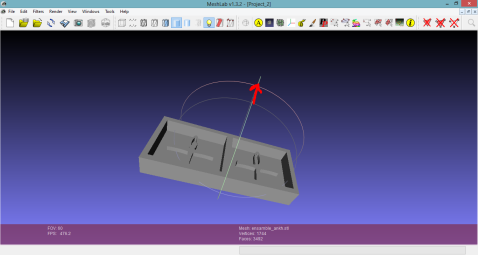
 With the "design" being done, it was time to mill the wax mold in order to generate the negative mold, however, when I opened the STL file created from my Inventor file, The view appeared tilted in the z-axis view, not really sure what to make of it, I opened the STL with Meshlab to check it out. In the picture, the z-axis is marked in red, so clearly the model was tilted, back to inventor.
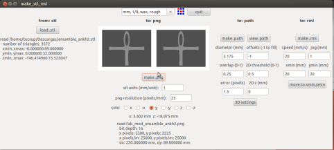
After recreating the
constraints for the
model in inventor, I re-exported and tried again in the Fab Modules,
this time the situation was slightly different:
The STL file was properly aligned ...in the y-axis! Not being really sure of what to do, and since the machineable wax was alreay in a vertical position, I returned to Inventor and changed the constraints, this time, the model was just right.
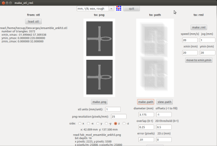
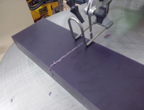 Previously, I had the wax cut with a scroll saw available at the lab, then, I Generated the path for machining and as I started working, we realized the wax piece was to small for the design, so, I used the fabmodules stl units setting in order to change the scale and make it fit into the piece, this would ultimately be fatal for the piece, as the miller did not recognize the curved part of the piece and would ignore most of the intended design entirely, I had paid dearly for my carelessness.
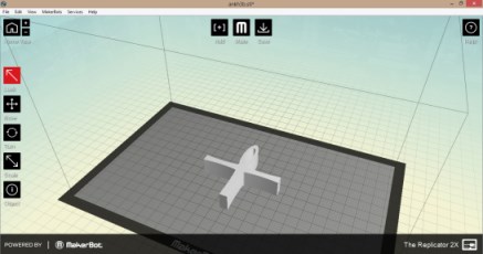
So, with the wax out of the game, since my machine time was over, I decided to switch my workflow, returned to my first model, and had it 3d Printed.
Since I intended to use the 3d Printed piece to make the negative in order to cast, I needed the piece to be as detailed as possible, so I chose high quality settings: 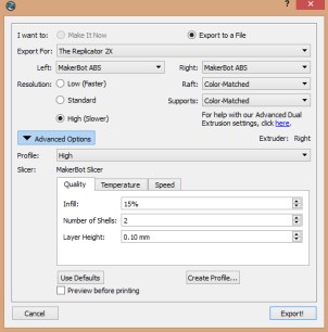
The printing process took over an hour and a quarter and had to be done twice (remember the I found a glitch in your SD card error from the 3D printing assignment? It happened again) And yet, the printing ended, and I had the piece ready:
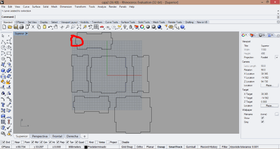
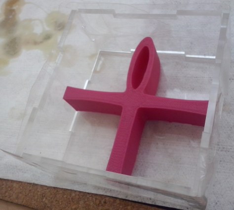
The next was to create an enclosure in order to pour the Smooth-on and capture the shape of the 3D printed piece. I worked on a previous design by michael and made a laser-cut acryllic press-fit box for the enclosure. My laptop was out of power so I used Rhino in one of the lab machines to make it. At first, I made a mistake regarding the measurements of one of the pieces (marked in red) adding unnecessarily the material thickness to the piece length, after correcting it, the enclosure worked.
I sealed the enclosure with duck tape in order to prevent the smooth-on from leaking, and to make the unions tighter 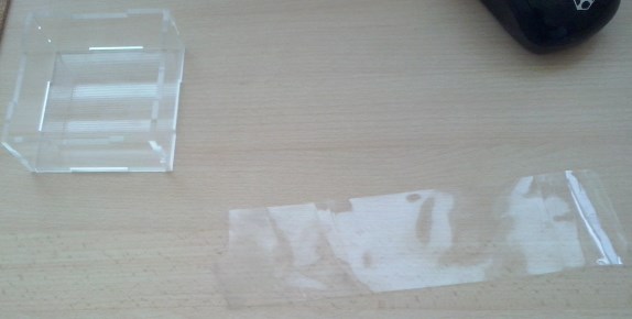 The enclosure was
designed to contain the 3d printed ankh with
enough room to let the smooth-on flow through and around the object,
originally I thought the piece would be somehow attached to the walls
of the enclosure, the axis of the cross were parallel to the walls of
it:
However, as it was
not realiable to get the ankh
stuck to the bottom of the enclosure, and in doing so, I would not
create a negative mold, but four, i decided to place the ankh in the
diagonal line of the enclosure, but first I needed to prepare
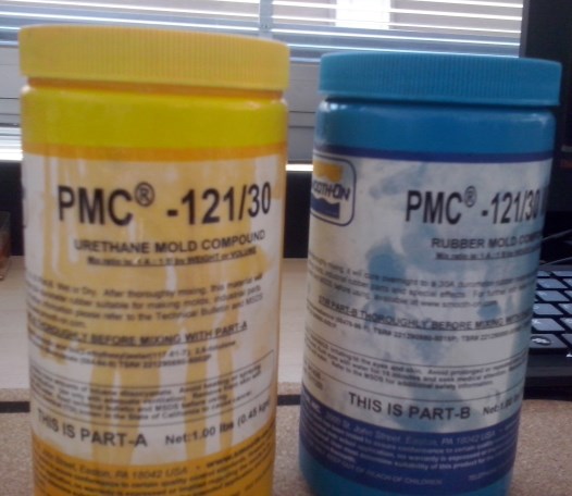
the Urethane.
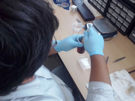
Equal parts, a plastic disposable glass, some stirring and mixing in the glass, and it was ready, time to pour:
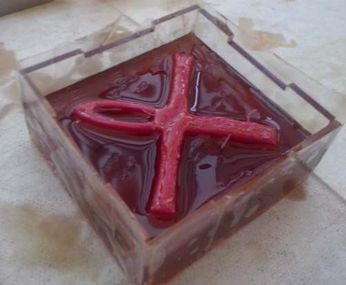
At first, I poured the urethane on the enclosure in order to make the 3D printed piece bond to the "floor" thus made, then, it became clear that it was a better idea to let the piece float freely and let the urethane cover it 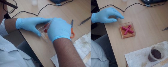
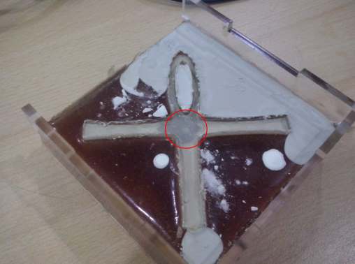
As i was filling the enclosure, I noticed that the round part of the cross was prone to dive deeper into the urethane that its counterpart. Since the mold was meant to be as leveled as possible, I manually held the piece in the right place until the urethane was consistent enough for the printed piece to keep in place. 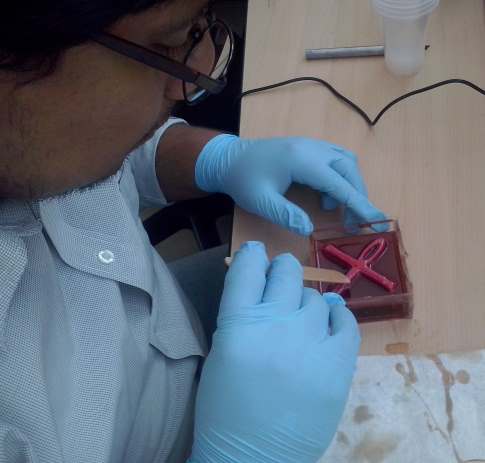 So I had the enclosure, the urethane inside of it, and the printed piece submerged into the urethane. I was kind of messy, but it was done.
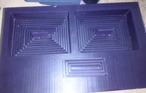
This process was not without incidents, in the end, a little urethane poured through the the joints of the enclosure, however, it was of no consequence, on the other hand, as it can be seen in he photo above, the visible face of the ankh is "dirty" this because it was the "raft" side of the printing and removing the raft from the print left residues. Therefore, the "clean" face was used to directly interact with the urethane was the "dirty" one was left on top. Four hours later I was able to remove the printed piece and obtain the negative mold, as I was getting started on it, I realized that although I had sealed the enclosure with duck tape and it was press-fit, some urethane managed to leak through, this would not be of consequence, fortunately. 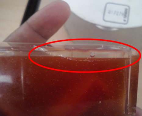 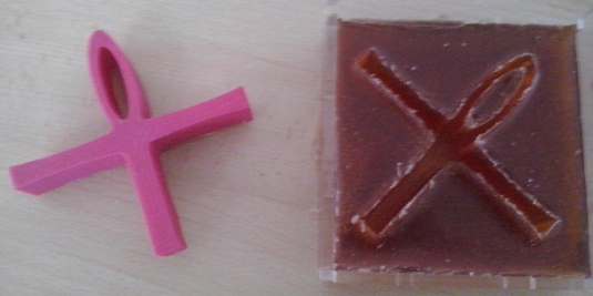 Having the negative mold ready, it was time for casting, Hydrostone was at hand, So I decided to use it. First I had to prepare the mix.
Then, it was time to cast the Hydrostone into the negative Ankh mold.
Then, the waiting game, I left the mold on a ledge outside the lab while waiting for the Hydrostone to get solid, the skyline was somewhat impressive: 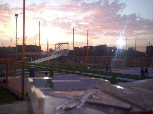 An hour and a half later, I was ready to demold, this time was a lot less difficult than the previous one with the 3d printed piece, but before moving on to that, a couple comments: first, there seemed to be too much water in my Hydrostone mix, so any small tilting made some drops of it pour out of the mold into the surface, I added a little more mix (I made more than enough) to compensate, this would leave a mark (in red).
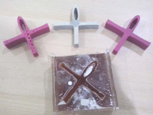
The demolding went without incidents, with the exception of the top side of the piece not entirely flat because of the final mixture addition I made at the end, that would need some sanding.
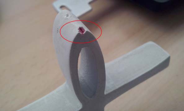
Finally, in order to cure and finish the casting, we set up the convection oven to heat up the piece. 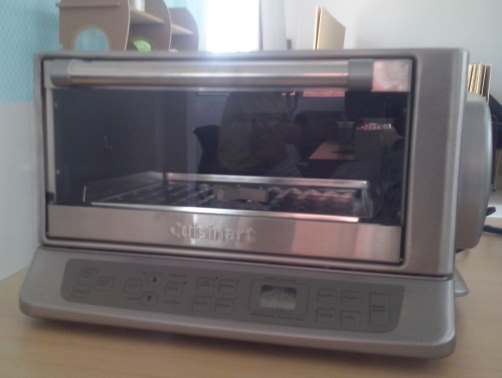 At first, in order to give it a go, I placed the piece for 15 min. at 150 °F, no substantial change noticed. 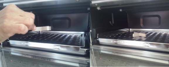 I tried a second time with 250 °F for 30 minutes, though it would only make about 15, since the 120-240 transformer we were using blew a fuse, just too much power from the oven. This time, however, there was a significant change in color and texture. After sanding, it was almost ready: 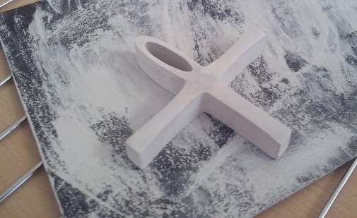 As I was sanding, I noticed someting interesting, in the upper region, something like a bubble hole was seen, but it was no bubble, instead, the pinholder part of the 3d printed piece (yes, it was too small) was cast along the Hydrostone and encased in it.
Conclusions?Design, Design, Design... take into account all possible variables: end mill, tolerances, dimensioning. In my case, this blew my wax mold Second, if you are using 3d printed pieces as first positive, make sure the piece is leveled.as you pour the urethane Third, this i cannot emphasize enough, be patient and work it out. Fourth, take into account Hofstadter's law into assignment planning, it -painfully- works. |